week-11 Joint creation and Demonstration
Objective: To illustrate revolute joint, translational joint, cylindrical joint and spherical joint using CONSTRAINED_JOINT
Procedure:
Joints Between Rigid Bodies:
1. Revolute Joint:
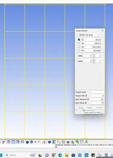
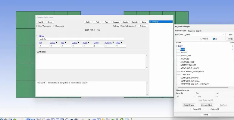
Use Shape Mesher to create 4N Shell with tow parts at a distance
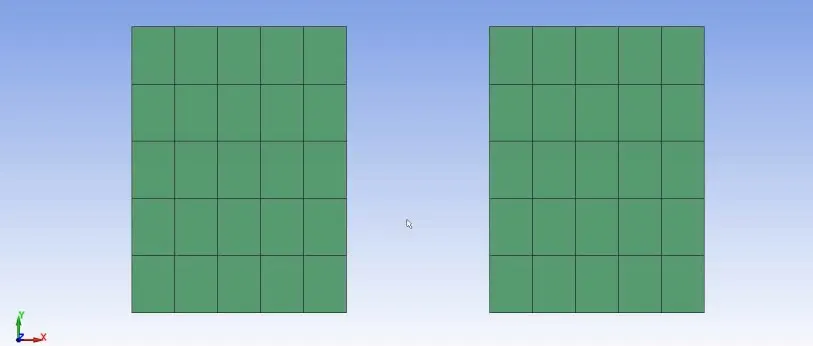
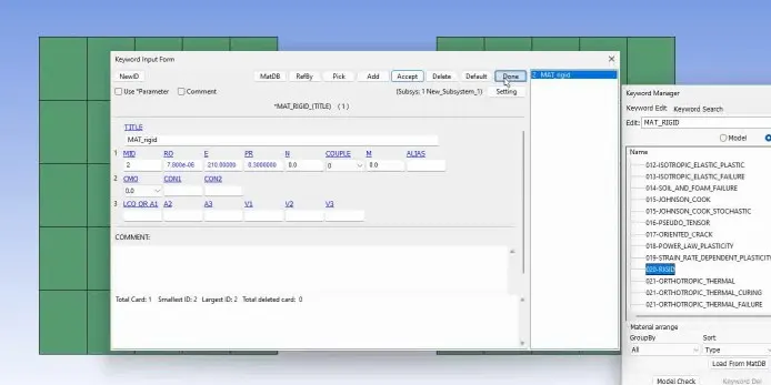
Create Material Property for Rigid Body
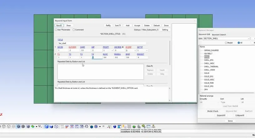
Create Section Shell
Assign material and section to Part
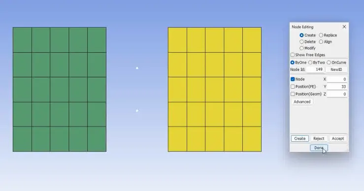
Create node using Node editing
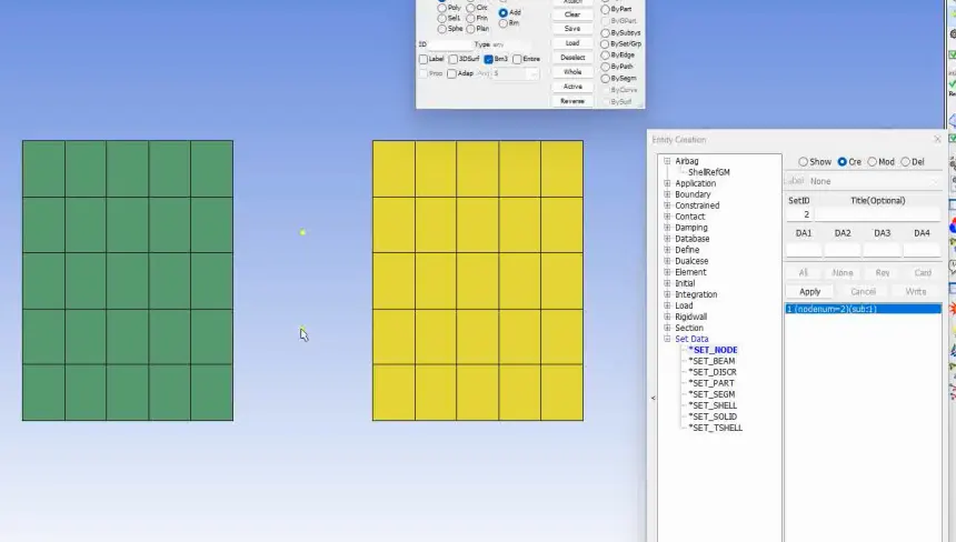
Create Node set and Extra node set
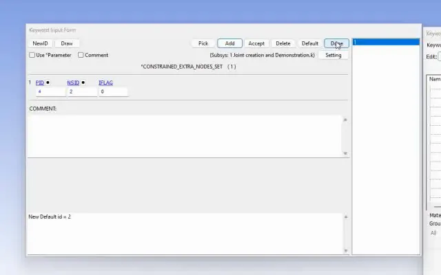
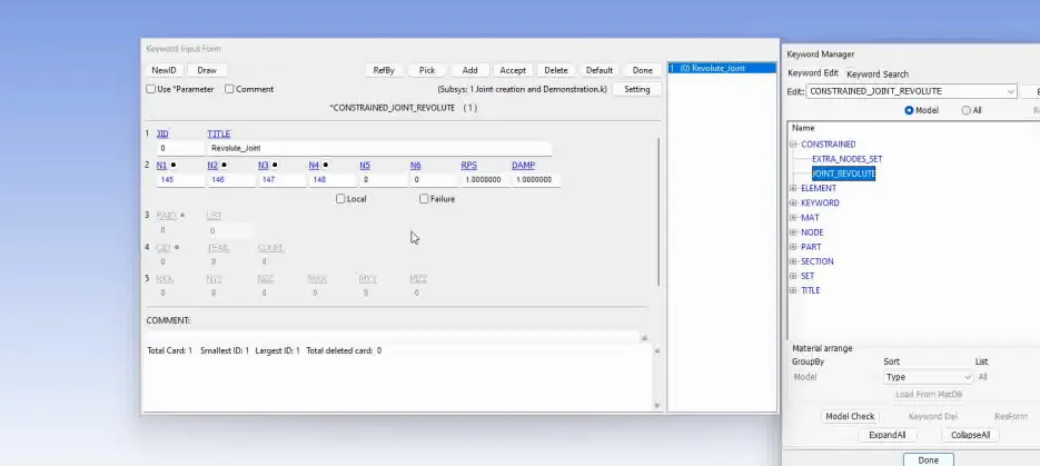
Create Revolute Joint
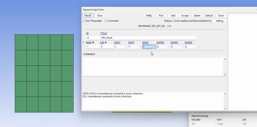
Boundary Condition
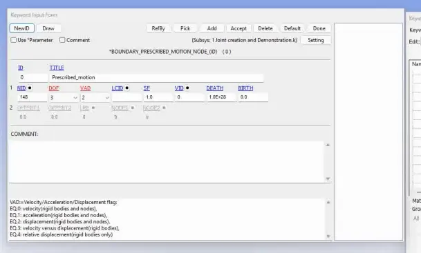
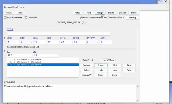
Similarly,
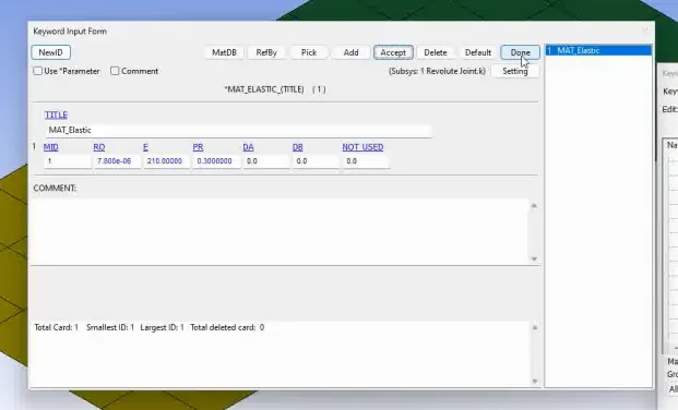
2. Revolute Joint for Deformable Body is Created by
Instead Rigid body Elastic material is considered
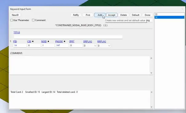
Constrained Nodal Rigidy Body
3. Spherical Joint
Create tow spherical joint using sphere shell in shape mesher
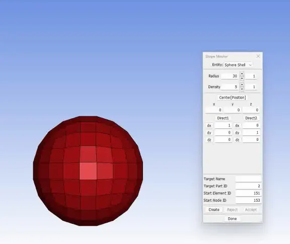
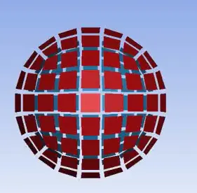
Material and Section properties are sama as that of spherical joint
Create two nodes. First node is contrained to Part 1 and second node is constrained to Part 2.
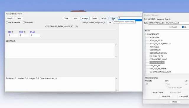
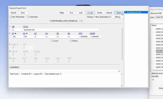
A Spherical Joint is then created between them, using the CONSTRAINED_JOINT
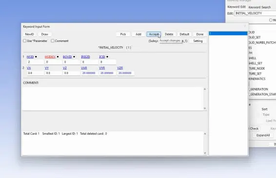
An initial velocity of 20 mm/ms is applied to part 2 that is inner sphere in all three rotational directions.
4. Spherical Joints beween Deformable Bodies
Similarly assign section, parts and materials card.
MAT_Elastic is defined instead MAT_Rigid
Instead Nodal_Nodes we will use Constrained_Nodal_Rigid_Body
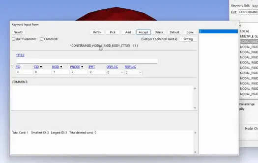
Instead INITIAL_VELOCITY_RIGID_BODY we will use INITIAL_VELOCITY to part 2
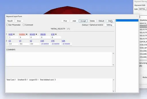
5. Cylindirical Joint
Two bodies are createed using shape mesher using cylindrical shell
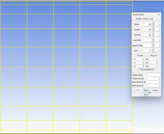
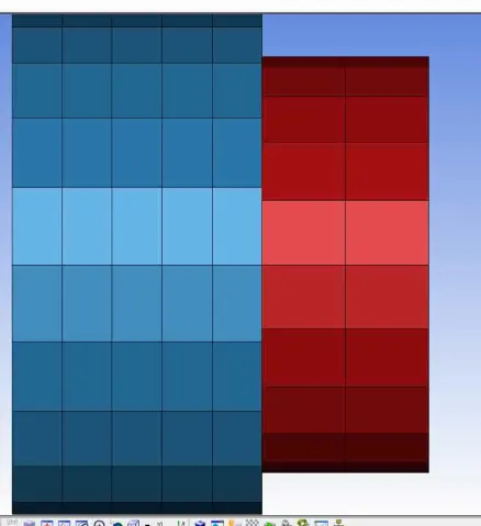
The material and section are created and defined to part.
Two pairs of nodes are creted and respective nodes are assigned for part 1 and part 2 using constrained_extra_nodes
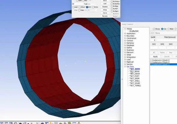

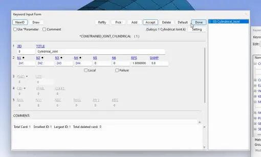
Cylindrical joints are created from nodes of part 1 and nodes of part 2
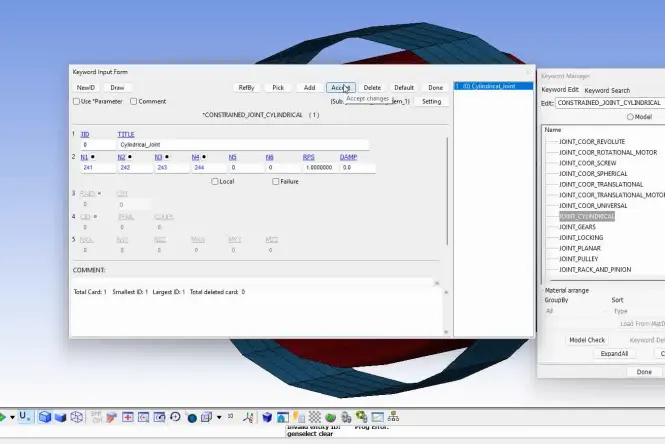
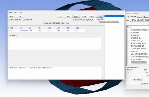
Initial Velocity of the Moving Part is 10 mm/ms
6. CYLINDRICAL JOINT FOR DEFORMABLE BODIES
For DEFORMABLE BODIES define MAT_EASTIC card with suitable parameters
Two pairs of nodes for constraining using node edit is created.
CONSTRAINED_NODAL_RIGID_BODY Card is created
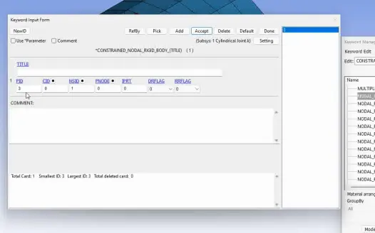
Cylindrical joint is then created between them, using the CONSTRAINED_JOINT menu using the nodes assigned for part 1 and part 2
7. TRANSLATIONAL JOINT
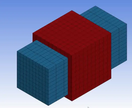
Two bodies are created via entity option in shape mesher
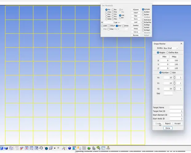
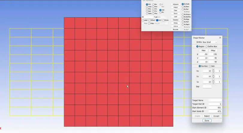
The material and section card are the same as of revolute joint
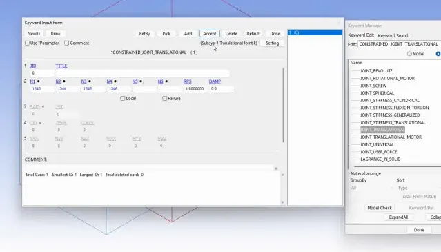
Three pairs of nodes for constraining using node edit option under element tools. First two pair of nodes are colinear and coincident. While other pair is slightly away from the axis and on the mid plane

CONSTRAINED card is used
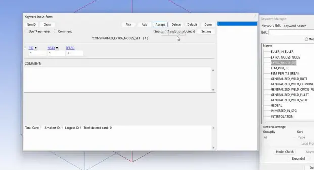
Joint is created
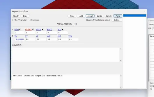
Initial velocity of 10 mm/ms is given for moving part
8. Translational Joint for Deformable Bodies
Similar Procedure is followed and MAT_ELASTIC is defined
CONSTRAINED_NODAL_RIGID BODY is created similarly for three pair of nodes.
Which is followed by translational joint and initial velocity
Conclusion:
Necesary keyword files are created for joints between rigid bodies such as spherical, revolute, translational and cylindrical joints tools.
Necessary keyword files are created and ran the simulation for ENDTIM of 5 ms and DTINIT is given as 0.01 ms.