week-11 Joint creation and Demonstration
AIM:
To create various joints such as revolute, spherical, translational, rotational, locking, cylindrical between two rigid and deformable bodies and simulate their relative motion between the bodies.
Procedure:
Spherical Joint between two rigid bodies:
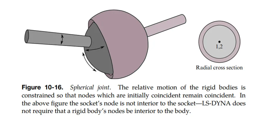
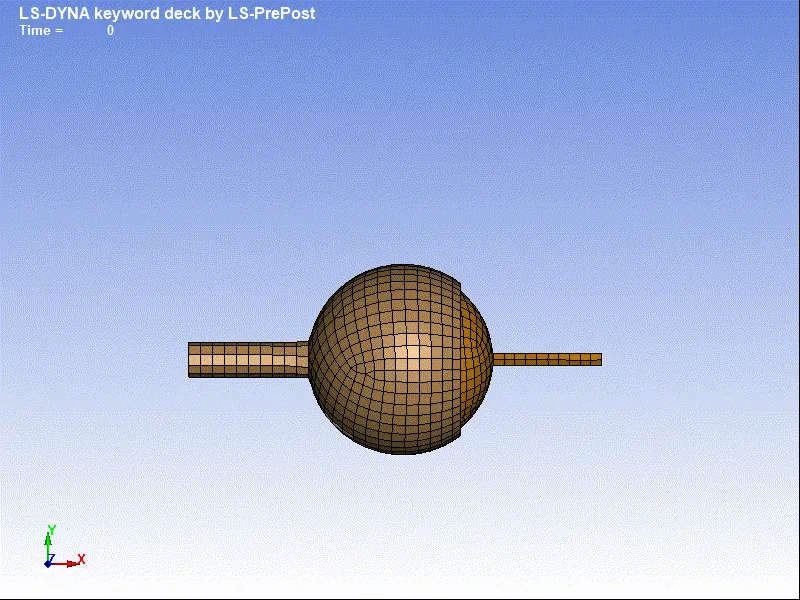
- A ball and socket model has been created using ANSA and it is imported to ls dyna.
- The unit system used in kg/mm/ms
- The socket is a sheet metal part with 2mm thickness and the ball is a solid part which is model as outer mesh with 1mm thickness and section card is created accordingly.
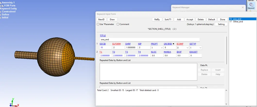
- Mat_20 rigid card has been created and assigned for both the parts.
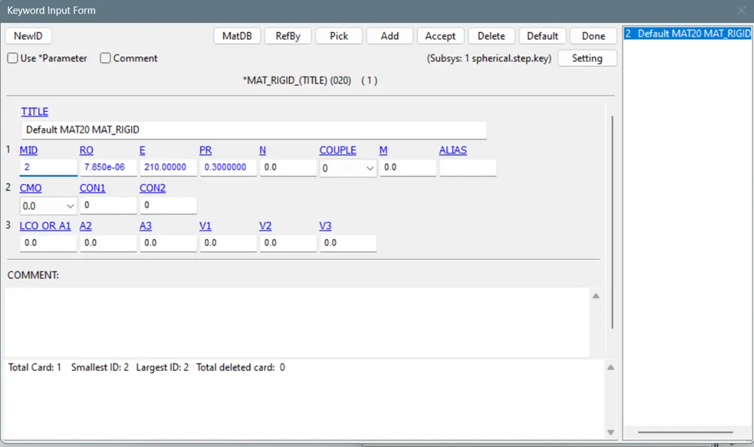
- To create a node at the cetre use Element tool>node editing>Create and select the avg centre option to create a node at the centre and similarly for another part.
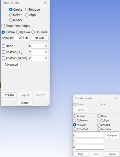
- Note the node id and go to Constrained>extra nodes>enter the node id and select the pid element and apply similarly for the another part.
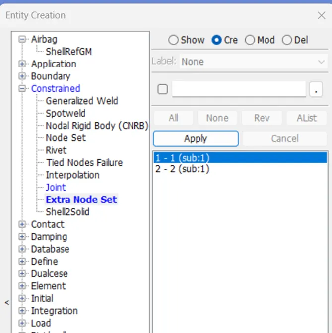
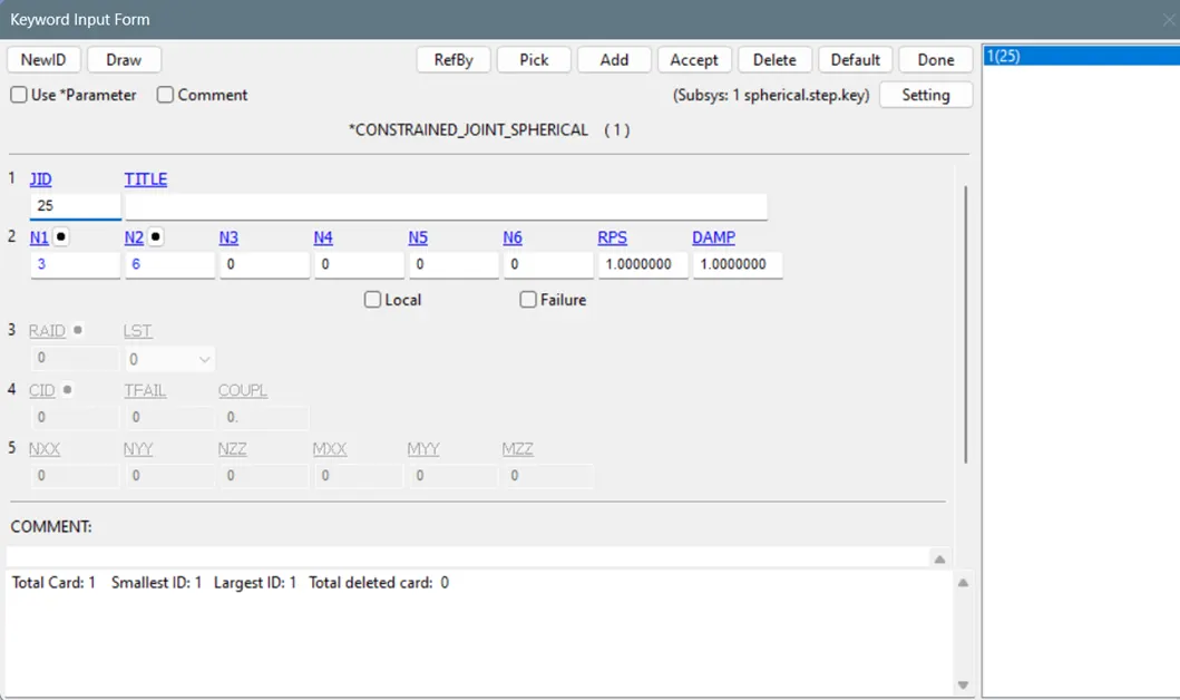
- Now go to Constrained>joint spherical>select n1 and n2 (which is the constrained extra nodes that we have created respectively for two parts)>accept and ok.
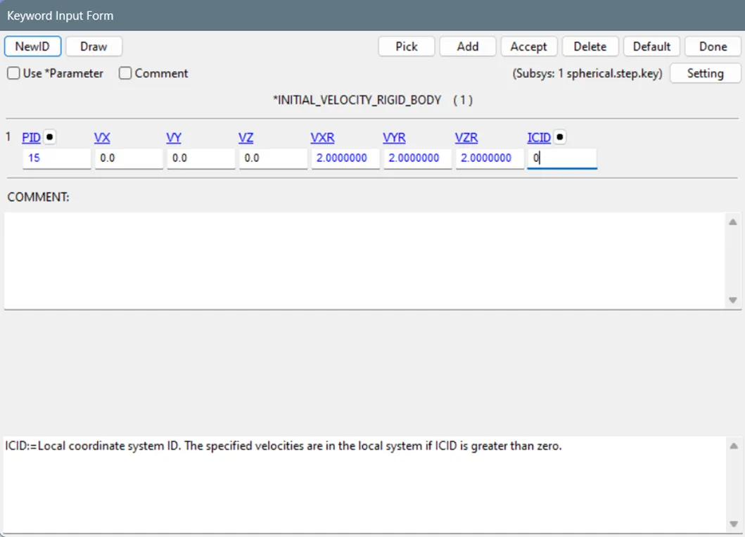
- Now to apply velocity for socket go to initial>velocity_rigid_body>Select the pid>Enter the initial rotational velocity in x,y and z directions.
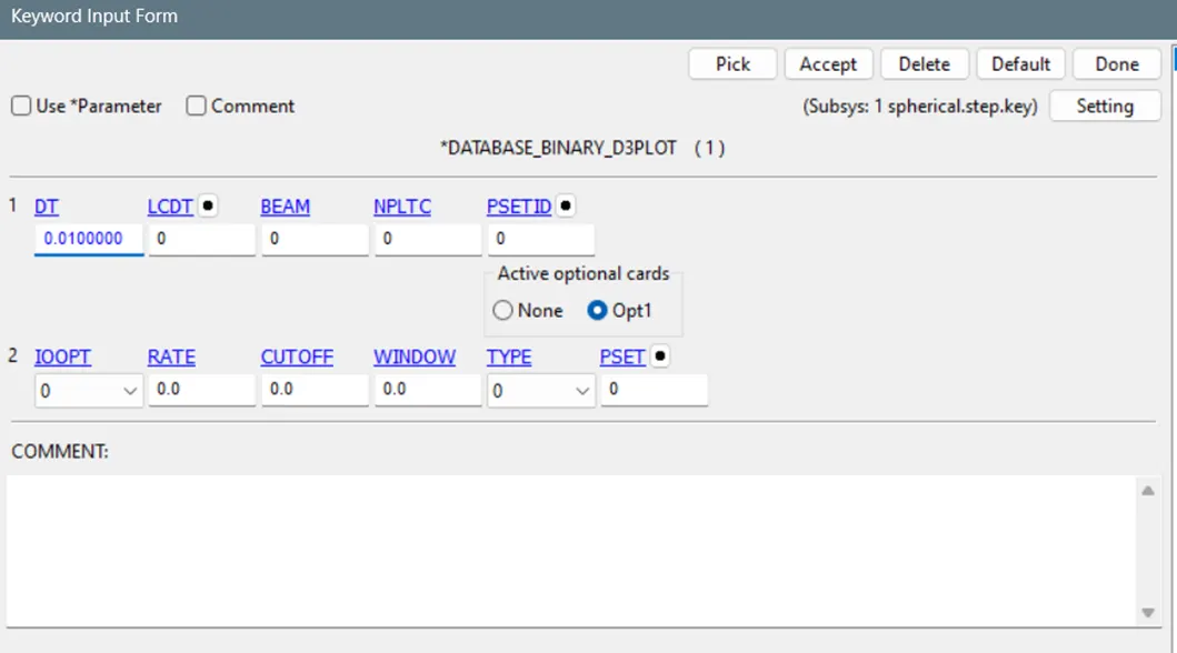
- Now Database>binary d3_plot for recording the animation.
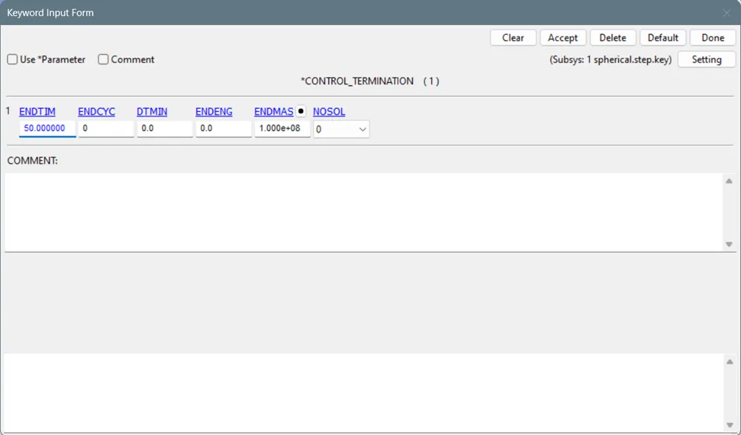
- Define control termination to specify the end time of the simulation.
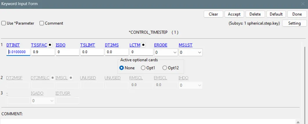
- Define control time step card to give initial time step size and TSSFAC as 0.9 so that if any fluctuation, model will converge.
- Now run the model using ls run and open the d3 plot file.
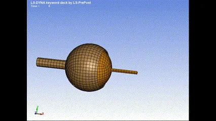
Spherical joint between two deformable bodies:
- Since the bodies are deformable, elastic material is used.
- So to create a joints, we need rigid bodies and we are going to create a Constrained Nodal Rigid bodies on ball and socket part.
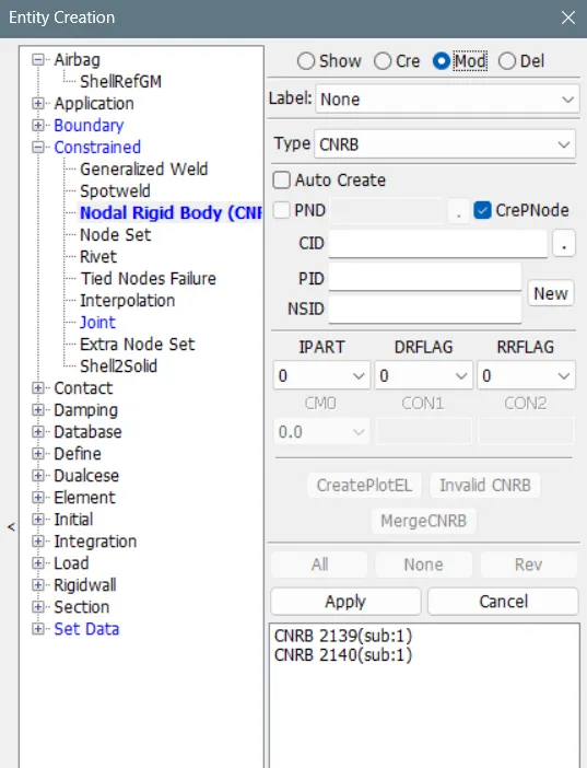
- Go to create entities>Constrained>Nodal rigid body>Check on CreatePNode option(will create node at the centre)>similarly for the other part.
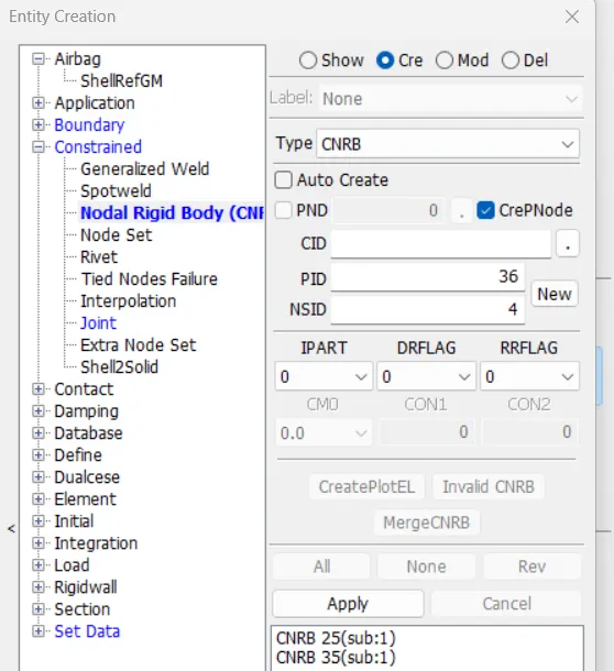
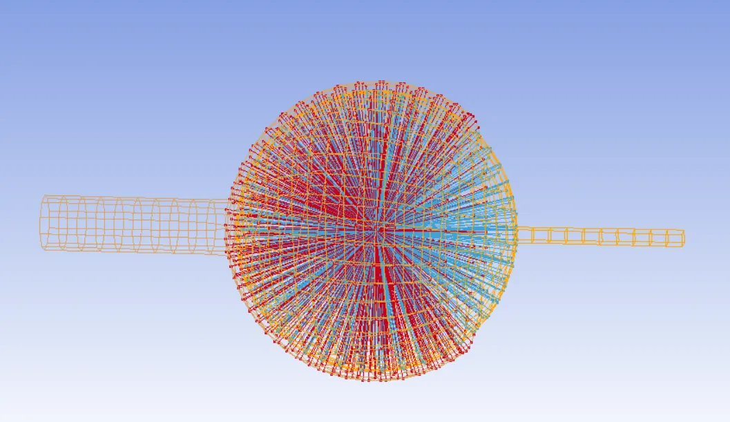
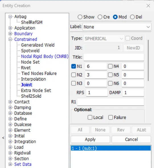
- Now that both the centers of the CNRB should be concident. Now go to Create entities>constrained>spherical>Selent the n1 and n2 as the centre of two CNRBs and apply>done.
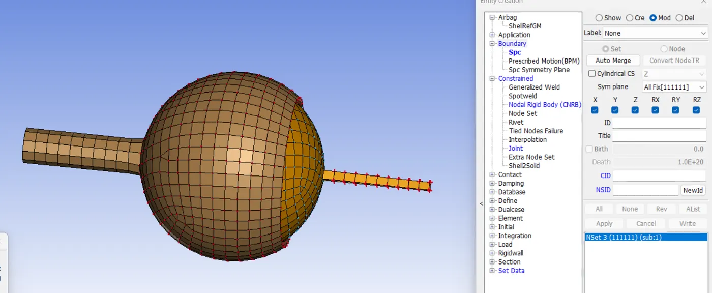
- Since it is a deformable body, We need to fix either the ball or socket end. Go to create entities>boundary>spc>select the nodes>apply.
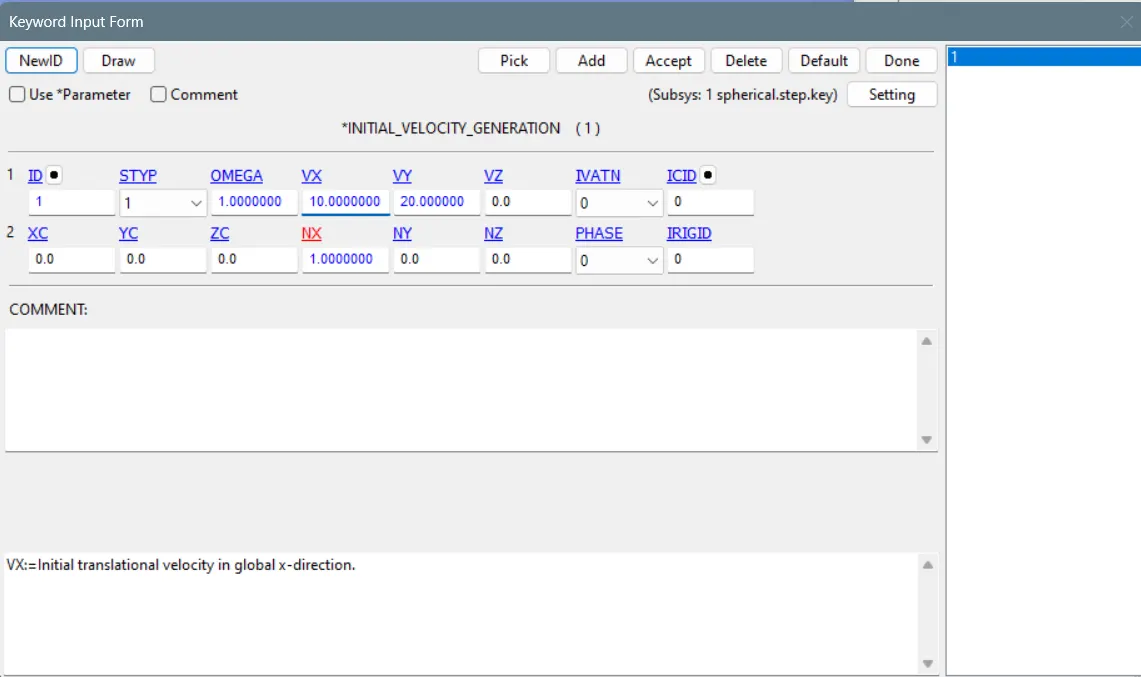
- To give velocity to the socket create node set and go to Control>velocity generation>To select part set id enter 1 in STYP column and give OMEGA as 1 and give velocity in x and y direction.
- The Remaining cards such as Control>termination,Time step, Database>binary d3plot, are similar to the rigid body model. You can open it in notepad++ and copy and paste and reload the model.
- Result:
Revolute joint:
- A two sheet metal plate has been created using ansa and it is imported to ls dyna. Both are deformable bodies so a CNRB has been created using Create entities>Constrained>nodal_rigid bodies.
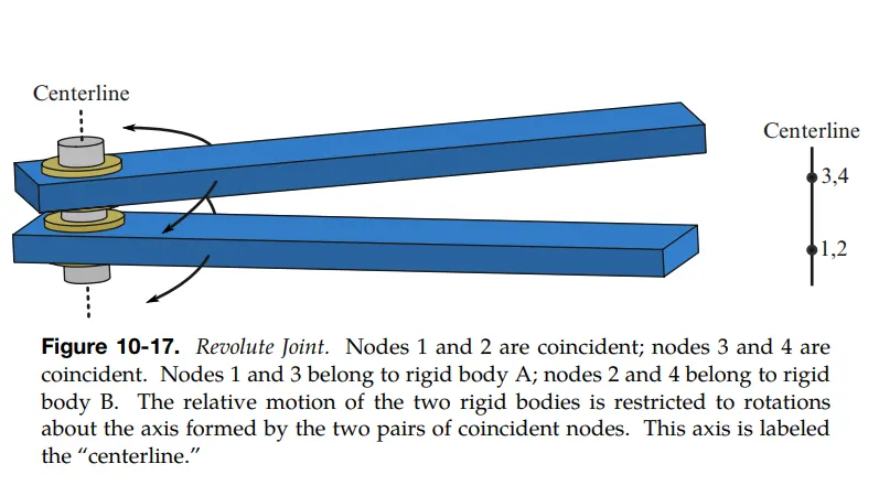
- Use modify option to create a branch from Both CNRBs to their COG point. So that node pair (1,2) are coincident and (3,4) are coincident. Node 1 and 3 belongs to part A and Node 2 and 4 belongs to part B.
- Now go to create entities>constrained>joints>Revolute>select the four nodes in order as explained above and apply, done.
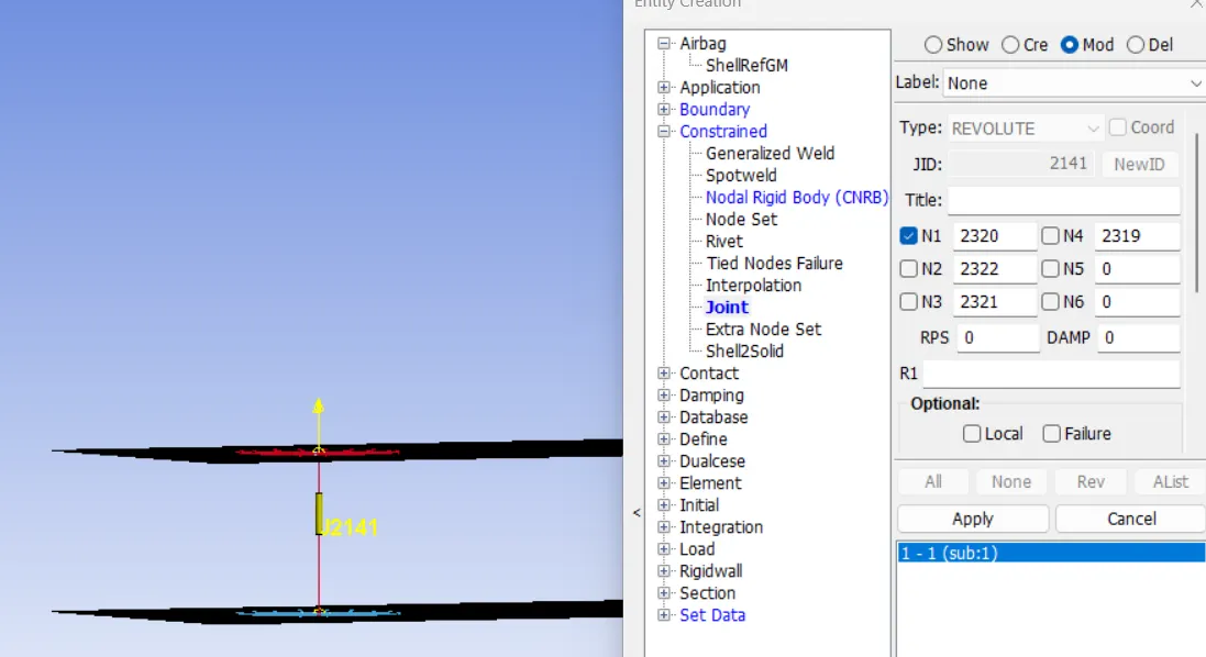
- Now one of the plate is fixed in all direction and the other is fixed in y direction so that it won't go out of plane x_z.
- Go to Create entities>boundary>spc>Select the plate a and fix all and other plate in x and z directions.
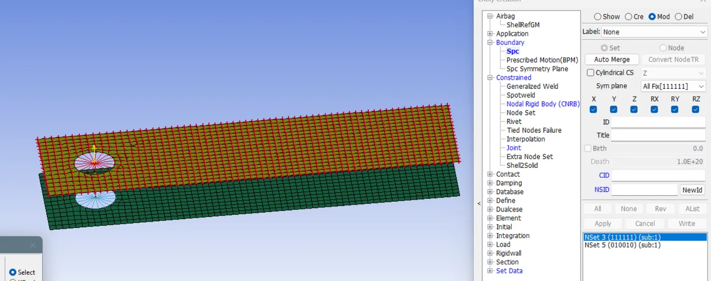
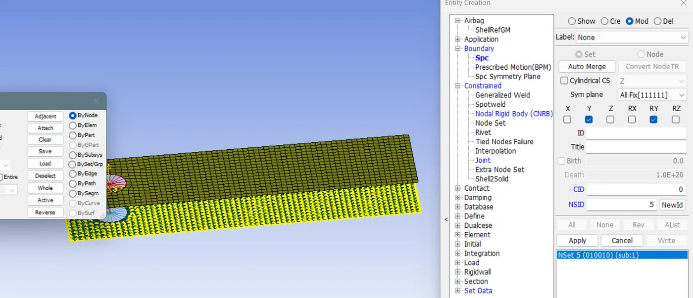
- The Remaining cards such as Control>termination,Time step, Database>binary d3plot, are similar to the Spherical model. You can open it in notepad++ and copy and paste and reload the model.
- Simulation of Revolute joint:
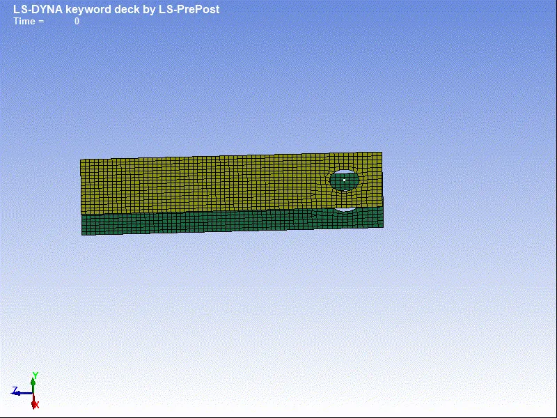
- Similarly for revolute joint between two rigid bodies, create rigid material and assign and create CONSTRAINED EXTRA NODE pairs respectively and create join as explained above.
CYLINDRICAL JOINT:
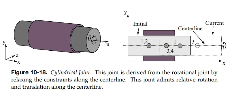
- A solid and a hollow cylinder has been modelled and imported to ls prepost.
- To define a Cylindrical joint between a rigid and deformable part, here solid part is considered as a rigid part and the hollow cylinder is considered as a deformable part.
- Section card has been created accordingly for shell and solids.
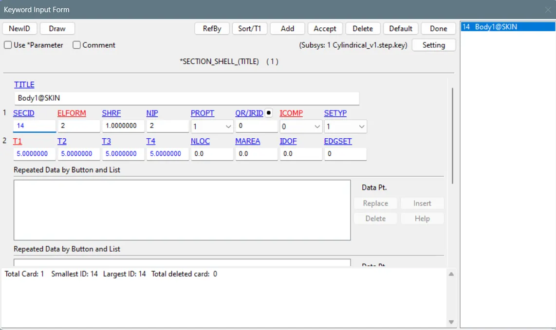
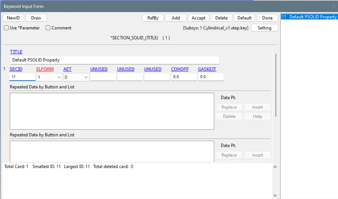
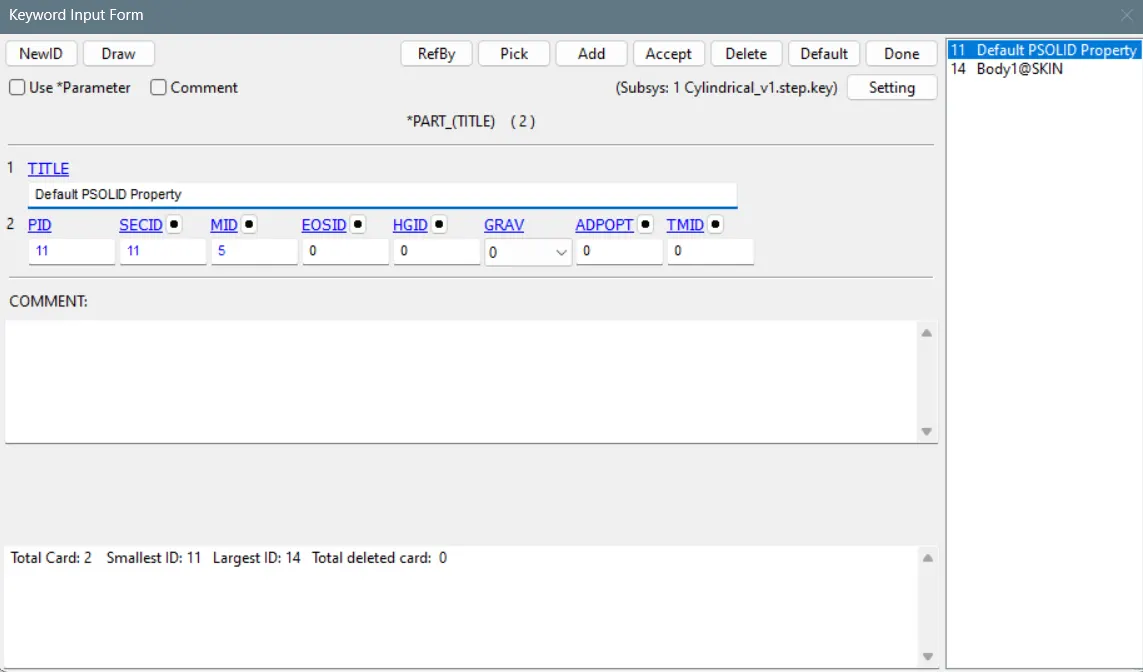
- Create Entities> CNRB for the hollow cylinder and Constrained_extra_nodes for the solid cylinder.
- The node pair 1,2 and 3,4 are on the center line similar to revolute joint. Node 1 and 3 belongs to solid part and node 2 and 4 belongs to hollow cylinder.
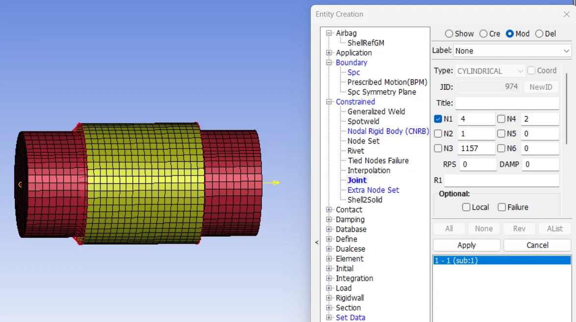
- Now the Hollow cylinder is fixed in all the direction using create entities>Boundary>spc>all_fix>select nodes>apply>done.
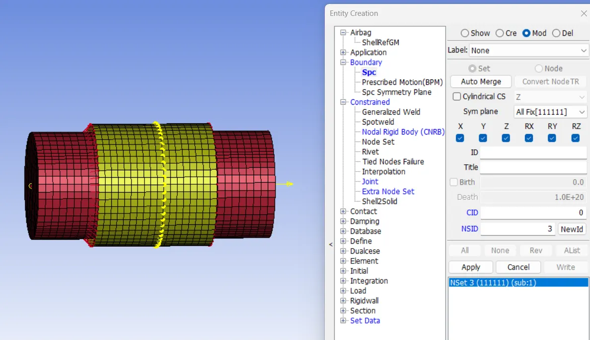
- Now the solid part is applies with 10mm/ms in y direction using velocity creation card.
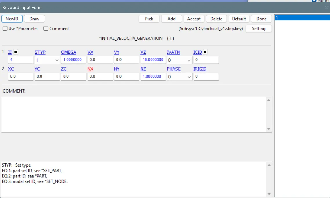
- The Remaining cards such as Control>termination,Time step, Database>binary d3plot, are similar to the Spherical model. You can open it in notepad++ and copy and paste and reload the model.
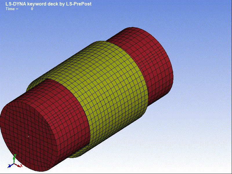
- Similation of Cylindrical model:
Translational Joint:
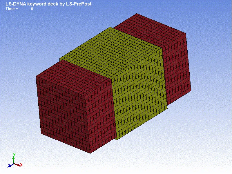
- A solid cuboid and a hollow cube has been modelled and imported to ls prepost.
- Now a constrained rigid body has been created using Create entities>Constrained>nodal_rigid_body.
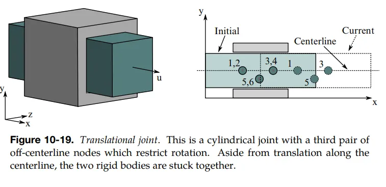
- The CNRBs of two bodies are branched in a way that node pair 1,2 and 3,4 forms a centre line and 5,6 should be branched which should not be in the centre line. node 1,3 and 5 belongs to part a, nodes 2,4,6 belongs to part b.
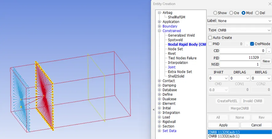
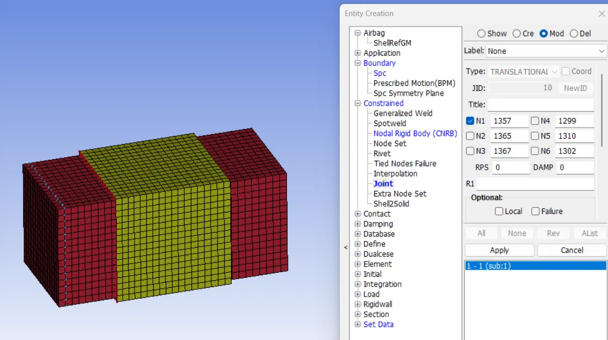
- Now the translational joint has been created using create entities>joints>select 6 nodes in oder as explained above.
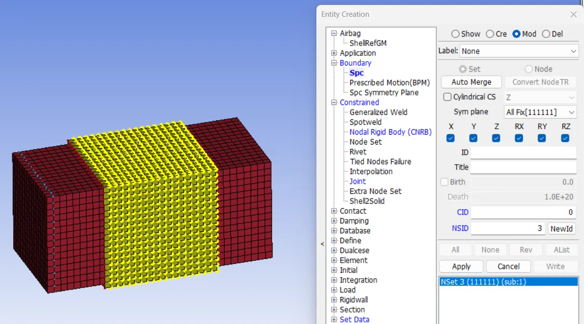
- Now the hollow cube is constrained in all the direction using create entities>Boundary>spc>all fix>apply>done.
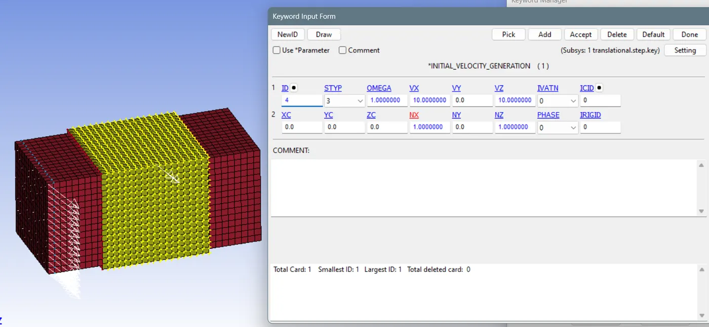
- Now the velocity has been given to solid cuboid part using Initial>velocity_generation>select the part id>give velocity in x and z direciton.
- The Remaining cards such as Control>termination,Time step, Database>binary d3plot, are similar to the Spherical model. You can open it in notepad++ and copy and paste and reload the model.
- Simulation of Translational joint:
CONCLUSION:
Thus various bodies has been developed defined as elastic and deformable bodies and joints such as spherical, relative, translational, revolute had been created and simulated successfully.