week-11 Joint creation and Demonstration
Aim: Using the manual (*CONSTRAINED_JOINT keyword) demonstrate spherical, revolute, cylindrical, and translational joints between two rigid bodies and two deformable bodies.
Revolute Joint:
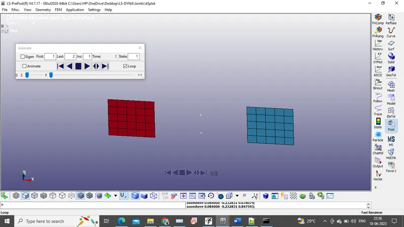
Revolute joint also called a hinge joint has one degree of freedom. This joint has pure rotation motion along a common axis.
Cylindrical Joint:
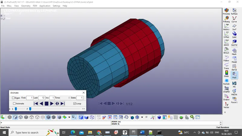
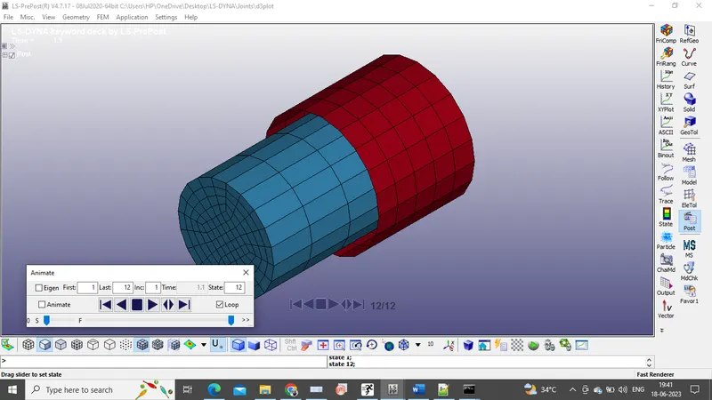
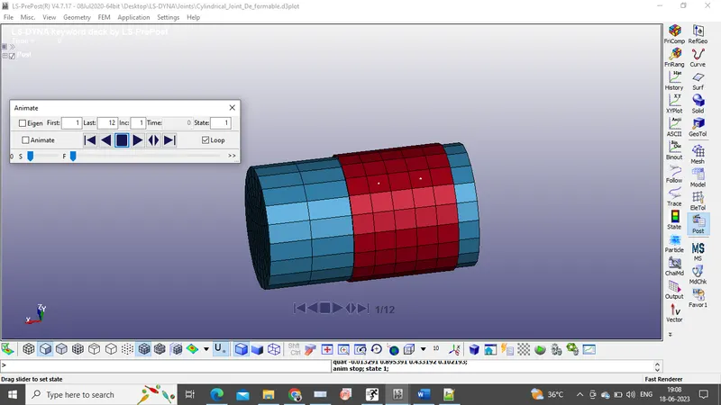
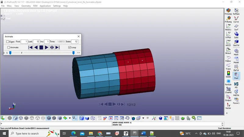
This joint admits relative rotation and translation along the centreline.
Translational Joint:
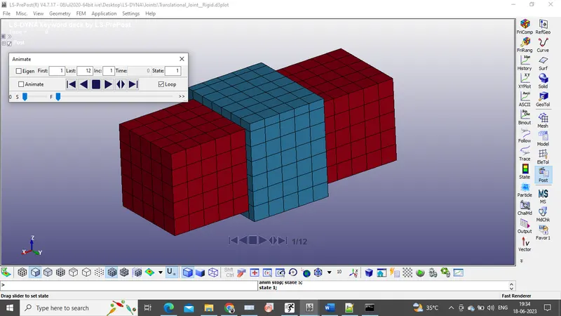
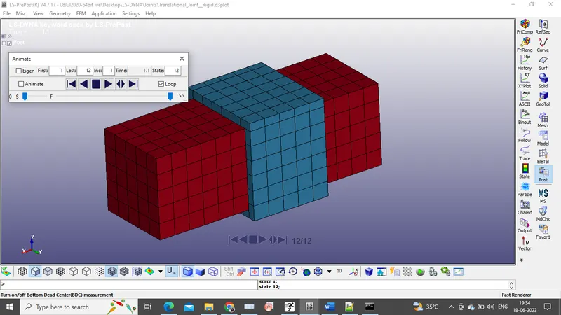
This is a cylindrical joint with a third pair of off-centerline nodes which restrict rotation. Aside from translation along the centerline, the two rigid bodies are struck together.
Spherical Joint:
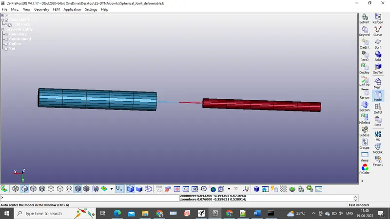
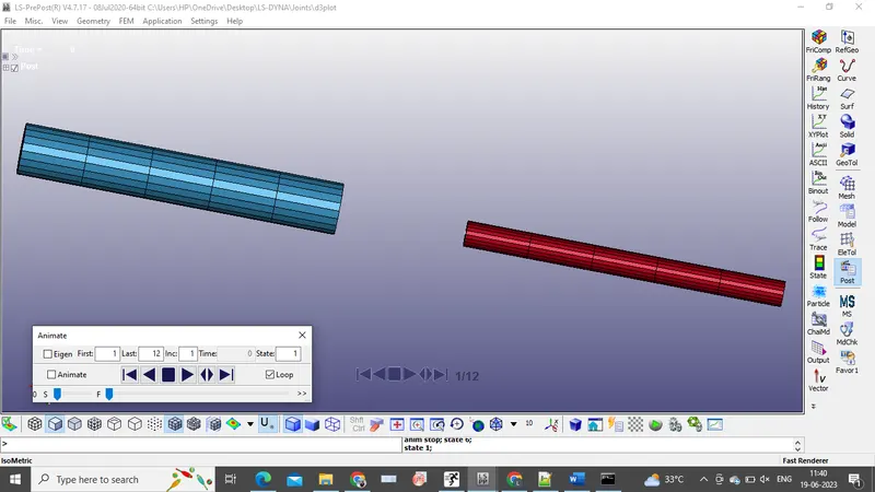
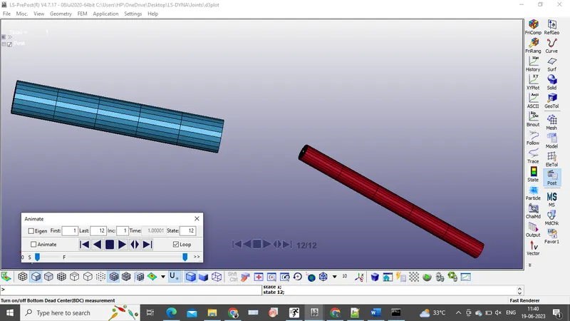
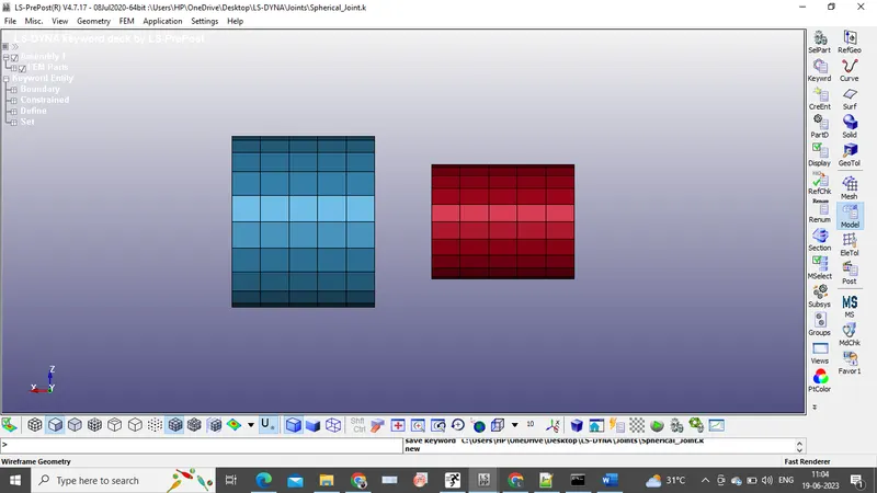
The spherical joint is the simplest of all joint, as the name suggest this joint have all rotational degree of freedom while all translational DOF are arrested. The relative motion of rigid body is constrained so that nodes which are initially coincident remains coincident.
RIGID BODIES:
Revolute Joint:
Procedure:
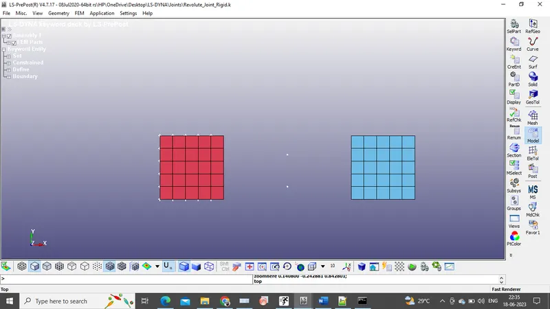
1)Two separate shell elements are separated by some distance are created to represent the geometry of the revolute joint.
2)Define the respective MATID and SECID for two parts. Shell section ID is assigned, whereas Rigid MAT card is used with steel properties (Units: g, mm, ms)
3)Four extra nodes have to be created which are further associated with two parts for making a revolute joint. Node_ID:100,101,102,103. Foe revolute joint N1=100 and N2=101 must be coincident and N3=102 and N4=103 must be coincident and the common axis is along through this nodes.
4)Create node sets, where nodes 100,102 belong to on set and nodes 101,103 belong to another.
5)Newly created nodes are in space and do not belong to any of the parts. So, for association these nodes with part1 and part2, *constrained_extra_nodes_set is used.
6)Using the *Constrained_Joint keyword, the revolute joint is created.
7)To make this joint work, boundary conditions are assigned. The displacement along z-direction is applied to one node in right side part. The Z-translational DOF is kept free by assigning DOF=3.
8)The left side part is fixed using the SPC keyword.
9)*Control_timestep card is used to make smaller time steps for explicit analysis.
10)*Control_Termination and Database keywords are assigned and the file is solved.
Cylindrical Joint:
Procedure:
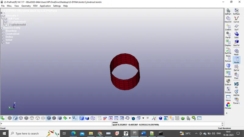
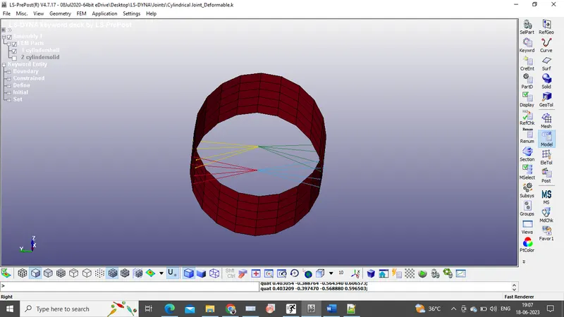
1)A Cylindrical shell and Cylindrical Solid has to be created using shape mesher in element and mesh group.
2)Proper SEC_ID and MAT_ID has to be assigned. Here, for the Shell part, Shell_Sec is assigned and Solid _Sec for the solid part. A common MAT_ID of rigid material is used.
3)Four extra nodes have to be created, to associate with the parts. Here, a set of nodes are coincided and both the sets are separated by some distance.
4)A *node_set_list keyword is created. Here Nodes 1 and 3 are assigned to one set and nodes 2 and 3 are assigned to other set.
5)As these nodes are in space, to connect the nodes to parts, *constrained_extra_nodes keyword is used.
6)Now create a cylindrical joint using *constrained_joint_cylinder keyword. Here, N1 and N3 nodes belong to part 1 and N2, N4 nodes are assigned to part2.
7)To perform desired motion, some boundary constants has to be deployed. So, the cylindrical shell is given a SPC keyword, whereas cylindrical solid is assigned with motion using *prescribed_motion_node keyword.
8)Finally for post-processing, specify the keyword and solve the input file.
Translatioanl Joint:
Procedure:
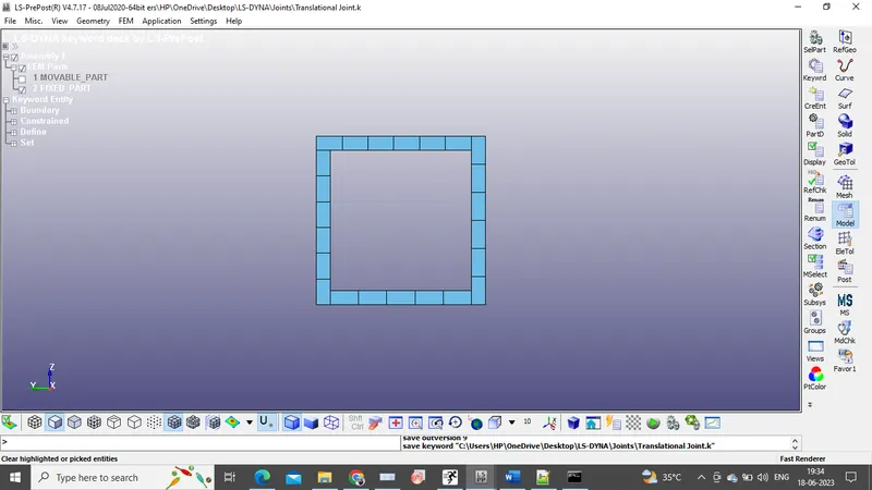
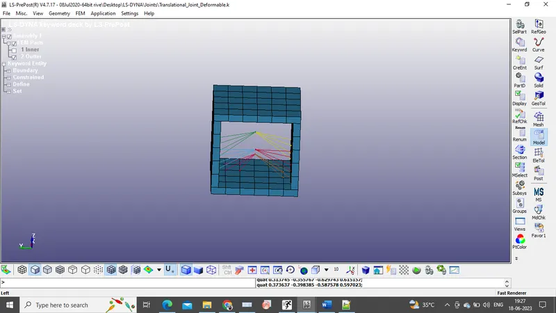
1)Firstly, a geometry has to be created for the translational joint. A movable box shell with x=150, y=50 and z=50 part is created and a fixed hollow box shell is also created.
2)Assign Shell_SEC_ID and *MAT_020 (Rigid material card) to the parts.
3)Create six extra nodes, which are further associated with the translational joint. These nodes are N1=1001, N2=1002, N3=1003, N4=1004, N5=1005, N6=1006.
4)Based on the translational conditions 2nodes representing different parts has to be coincided, so the node pairs are N1, N2: N3, N4 and N5, N6 (offset nodes)
5)Create node sets, which are further used to represent the parts.
6)Using *Constrained_extra_nodes keyword, the nodes are assigned to the respective parts, i.e, N1, N3, N5 to part1 and N2, N4, N6 to part2.
7)Now add the *constrained_joint_translational keyword to the list.
8)Boundary conditions has to be assigned to perform the required operation.
9)Finally, specify the output keywords and solve the input file.
Spherical Joint:
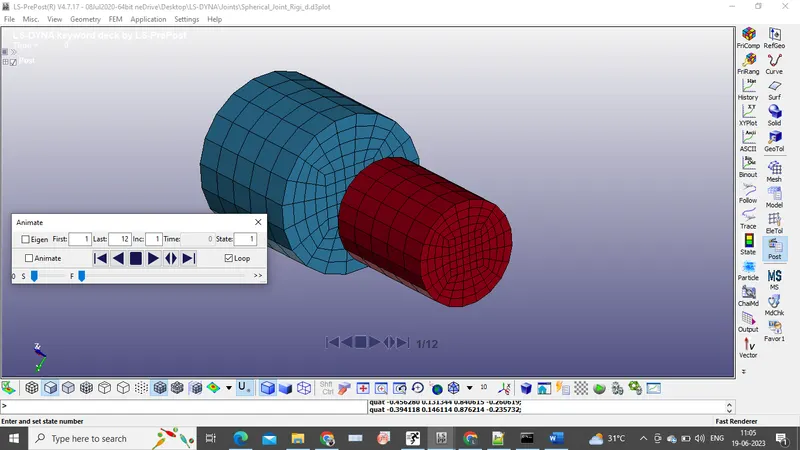
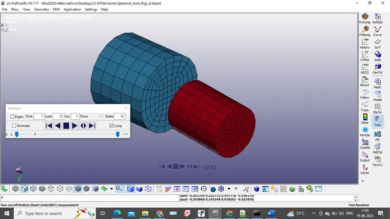
1)Cylindrical Solid has to be created using shape mesher in element and mesh group.
2)Proper SEC_ID and MAT_ID has to be assigned. Here, for the Solid_sec is assigned part. A common MAT_ID of rigid material is used.
3)Two extra nodes have to be created, to associate with the parts. Here,nodes are coincided
4)As these nodes are in space, to connect the nodes to parts, *constrained_extra_nodes keyword is used.
6)Now create a spherical joint using *constrained_joint_spherical keyword.
7)To perform desired motion, some boundary constants has to be deployed. So, the cylindrical shell is given a SPC keyword, whereas cylindrical solid is assigned with motion using *prescribed_motion_node keyword.
8)Finally for post-processing, specify the keyword and solve the input file.
DEFORMABLE BODIES:
Revolute joint:
1)In deformable bodies the MAT card to be used is elastic.
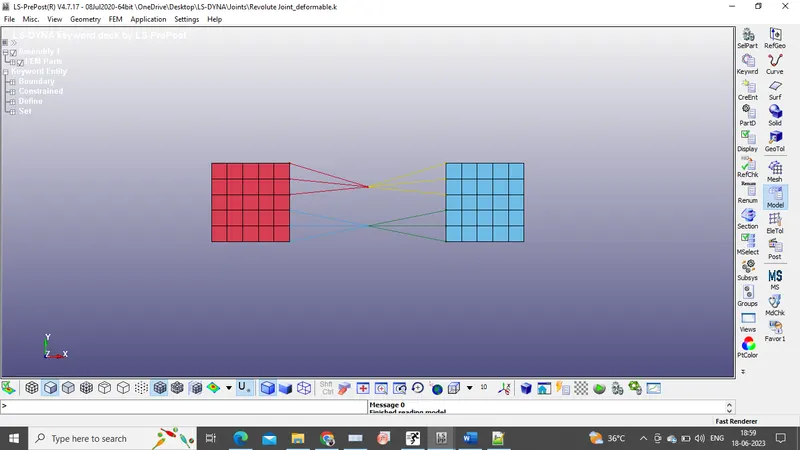
2)Four extra nodes must be created, CNRB shoud be created with PNODE at 100 and also PNODES at 101,102 and 103 must be done.
3)From revolute joint condition the nodes 100,101 and 102,103 must be coincidence, so use translate option to coincide the nodes.
4)Use *constrained_joint keyword to assign the nodes for revolute joint.
5)To make this joint work, boundary conditions are assigned. The displacement along z-direction is applied to one node in right side part. The Z-translational DOF is kept free by assigning DOF=3.
6)The left side part is fixed using the SPC keyword.
7)*Control_timestep card is used to make smaller time steps for explicit analysis.
8)*Control_Termination and Database keywords are assigned and the file is solved.
Cylindrical Joint:
1)In deformable bodies the MAT card to be used is elastic.
2)Four extra nodes must be created, CNRB shoud be created with PNODE at 1001 and also PNODES at 1002,1003 and 1004 must be done.
3)From joint condition the nodes 1001,1002 and 1003,1004 must be coincidence, so use translate option to coincide the nodes.
4)Use *constrained_joint keyword to assign the nodes for cylindrical joint.
5)To make this joint work, boundary conditions are assigned. The velocity along x-direction is applied to inner cylinder, using *initial_velocity keyword
6)The outer shell is fixed using SPC keyword.
7)*Control_timestep card is used to make smaller time steps for explicit analysis.
8)*Control_Termination and Database keywords are assigned and the file is solved
Translational joint:
1)In deformable bodies the MAT card to be used is elastic.
2)Six extra nodes must be created, CNRB shoud be created with PNODE at 1001 and also PNODES at 1002,1003,1004, 1005 and 1006 must be done.
3)From joint condition the nodes 1001,1002 and 1003,1004 must be coincidence, offset node 1005,1006 must be coincided. So use translate option to coincide the nodes.
4)Use *constrained_joint keyword to assign the nodes for tanslational joint.
5)To make this joint work, boundary conditions are assigned. The velocity along x-direction is applied to inner cylinder, using *initial_velocity keyword
6)The outer shell is fixed using SPC keyword.
7)*Control_timestep card is used to make smaller time steps for explicit analysis.
8)*Control_Termination and Database keywords are assigned and the file is solved
Conclusion:
Rigid Bodies:
Revolute Joint:
Cylindrical Joint:
Translational Joint:
Spherical Joint:
Deformable Bodies:
Revolute Joint
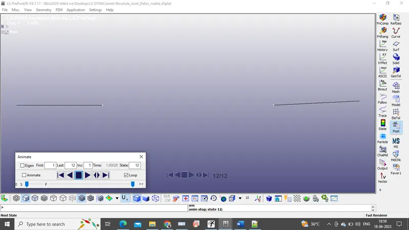
The right side plate is moving in Z direction w.r.t common axis.
Cylindrical Joint:
Translational Joint:
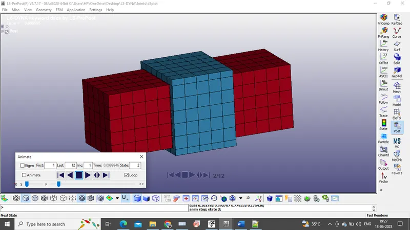
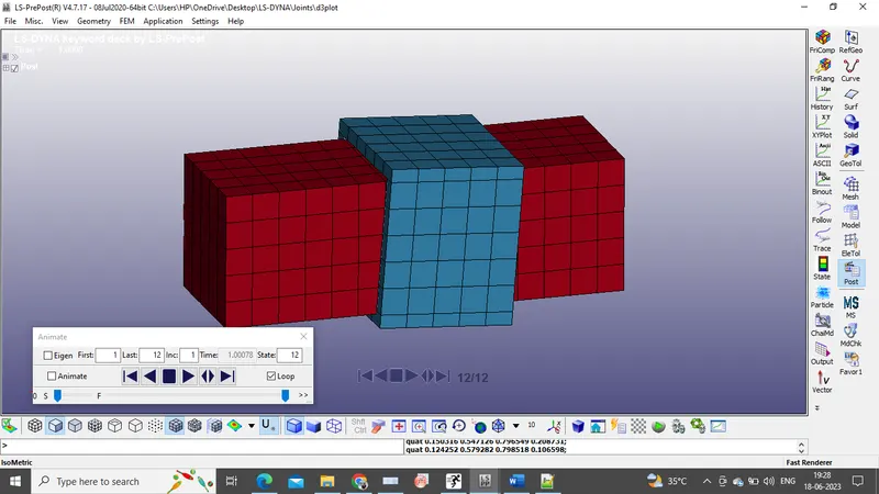
Spherical Joints: