Week 11: FSAE Car Project
Aim
- Run an aerodynamic flow simulation over an FSAE car in two phases
- First phase consist of setting up a coarse simulation
- For the second phase this should be done in two cases, One in which the car is traveling through a lot of turns and another case with car travelling in straight road
Phase 1
Case setup
- Firstly the errors in the geometry is fixed by deleting the overlapping and intersecting triangles and creating or stitching the vertices
- A virtual wind tunnel was created
- The flat part of the tire is deleted and the ground surface of the wind tunnel was connected to the open edges of the tire(the deleted flat part caused the open edge)
- A transient simulation was set
- A total of 8 seconds as end time with minimal time step being 1e-9
- Density based simulation is selected
- Boundary conditions are shown in snapshot given below
- For initialisation the same inlet velocity is given
- K-omega turbulence model is selected with Automatic wall function
- A base grid of 1 was given
- Fixed embedding was also enabled
- And finally in the post variable selection Y+ is added to output files
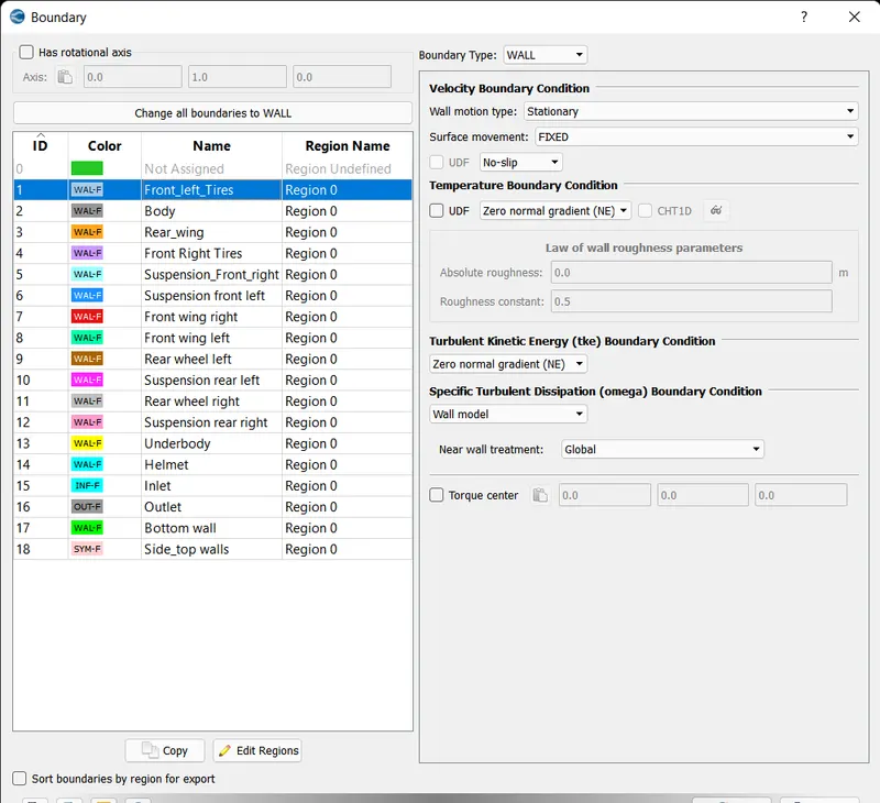
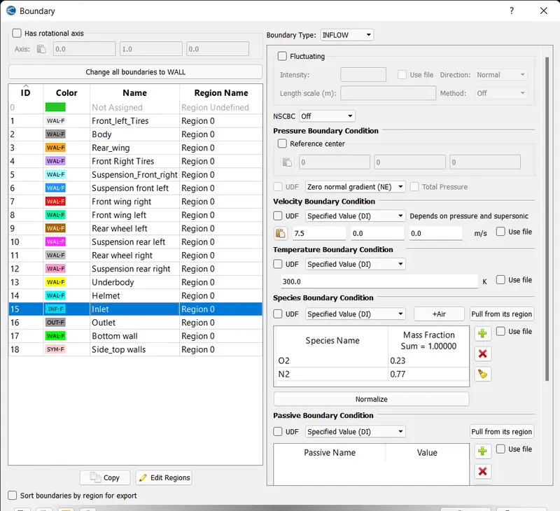
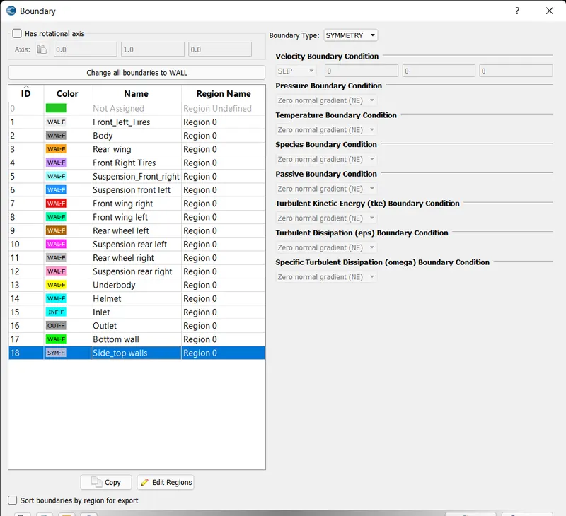
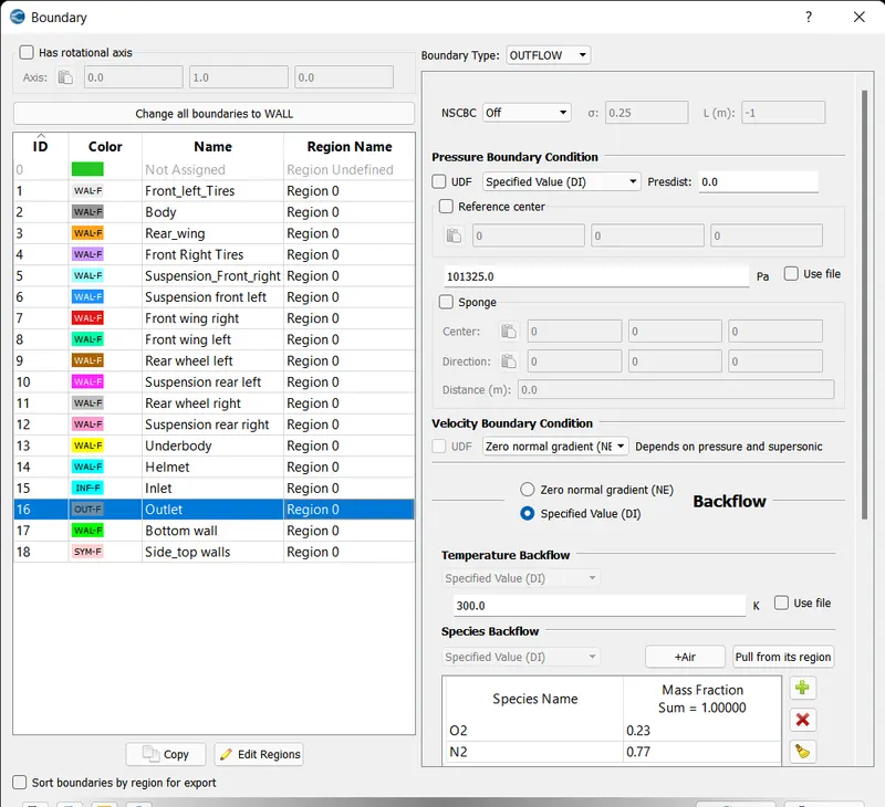
- All the other boundaries are defined as walls and conditions are the same as front left tyres
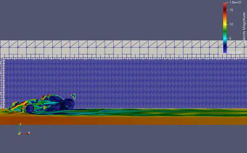
Output
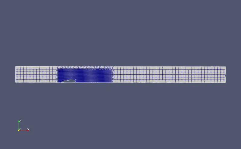
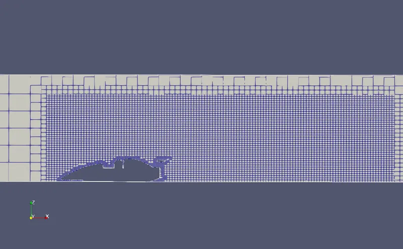
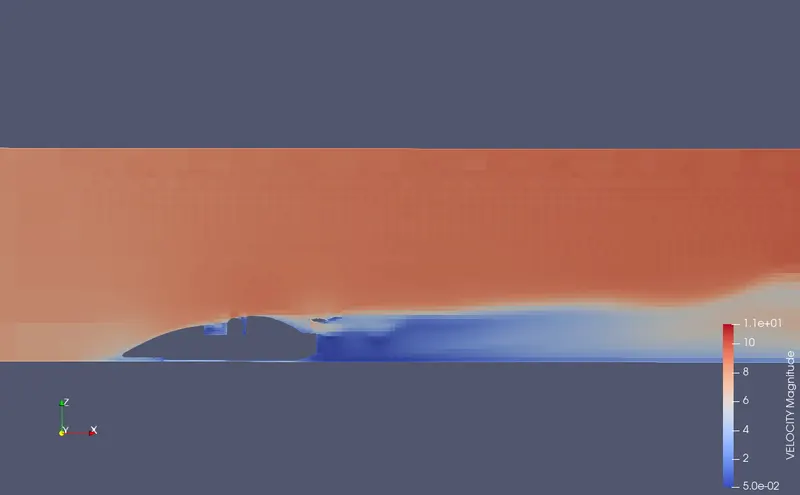
Observastions
- Simulation worked fine
- To increase the accuracy and computational efficiency we have work with mesh
- Another setup is created by reducing the base grid sizes and changing the fixed embedding scales
Phase 2
Case setup
- Turbulance model is changed to k-epsilon
- Base grid is refined to 0.32,0.25and 0.25 in x,y and z directions
- Fixed embedding scale is set to 3 for all the boundaries and to the fixed embedding box
Case 1- Track with a lot of turns
- Here the geometry is turned from its initial positon(parallel to sideplanes ) in an angle which avaraged from the three cases here(45,80,20)
Outputs
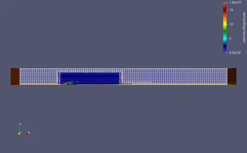
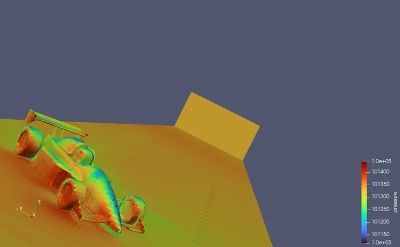
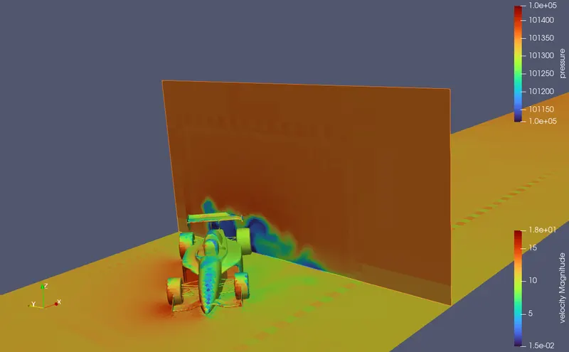
Pressure contour
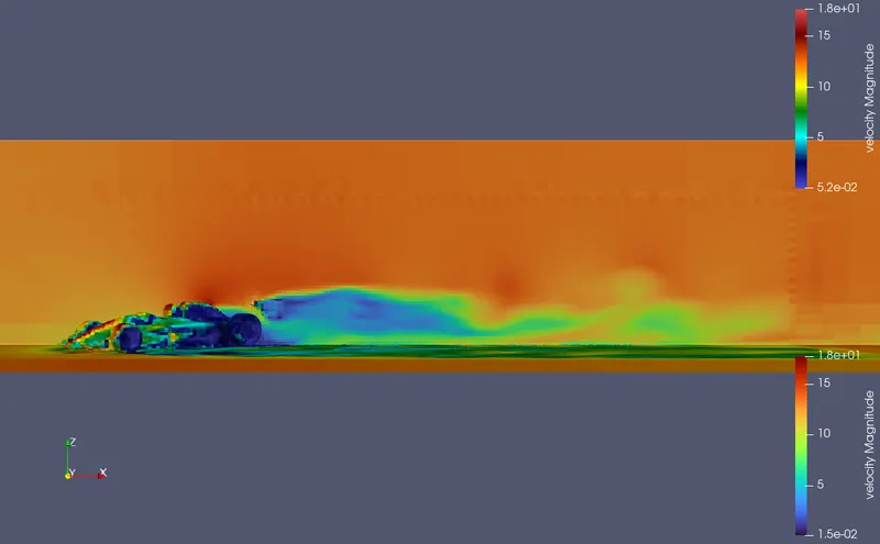
Drag and lift
Pressure forces
| Boundary ID | Name | Pressure force in X-direction | Pressure force in Y-direction |
| 1 | Body | 3914.53 | 38.66 |
| 2 | Rear wing | 3.82 | -6.02 |
| 3 | Front wheels | 9.83 | -3.02 |
| 4 | Rear wheels | 8.12 | -2.8 |
| 5 | Front wing right | -102.5 | 184.15 |
| 6 | Front wing left | 186 | -105 |
| 7 | Front suspension right | 8.4 | -2.8 |
| 8 | Front suspension left | -3.92 | -9.82 |
| 9 | Front suspension right | -9.9 | -19.61 |
| 10 | Rear suspension right | -19.6 | -9.8 |
Observations
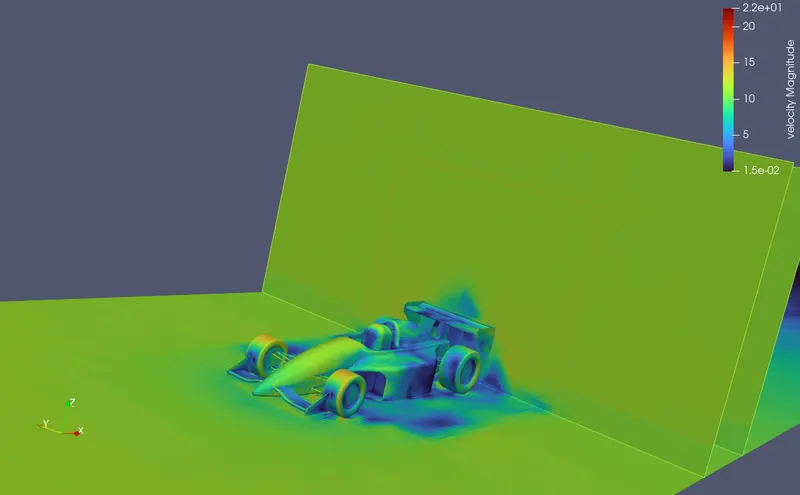
- From the above velocity contours we can see there is more wake region at the rear side
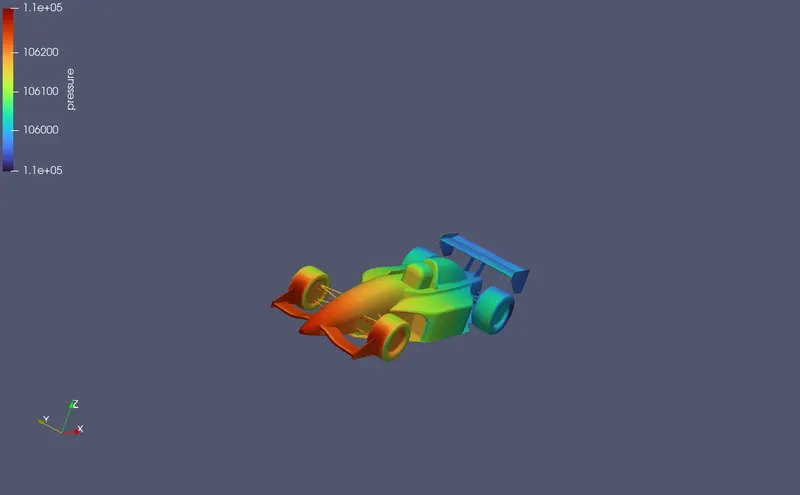
- The side of car body which is facing the flow encounters more pressure
- The rear wing produces negetive lift which enhances the movement and grip of the car. Also this part of car have less drag force
- The front wheels also produces negetive lifts followed by rear wheels
- The left front wing gets more negetive lift also the tires need more grip at this point since the car is taking a turn. So the front wing of car have a significant property while turning
- Since the car is taking a turn the drag force the car encounter is more since the frontal area of the car is more
Case 2 - Track with straight road
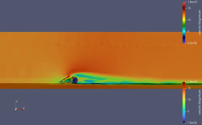
Outputs
Drag and lift
Pressure forces
| Boundary ID | Name | Pressure force in X-direction | Pressure force in Y-direction |
| 1 | Body | 5790 | 0.45 |
| 2 | Rear wing | 1.6 | -0.19 |
| 3 | Front wheels | -5.41 | 2.925 |
| 4 | Rear wheels | -4.7 | 0.19 |
| 11 | Front wing right | -60.84 | -215 |
| 10 | Front wing left | -60.84 | -215 |
| 6 | Front suspension right | -4.85 | 8.44 |
| 7 | Front suspension left | -4.85 | 8.44 |
| 8 | Rear suspension right | 21.78 | 7.23 |
| 9 | Rear suspension left | 21.78 | 7.23 |
Observations
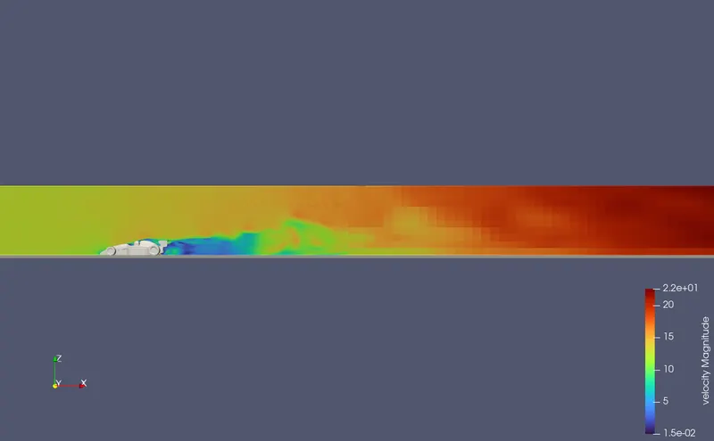
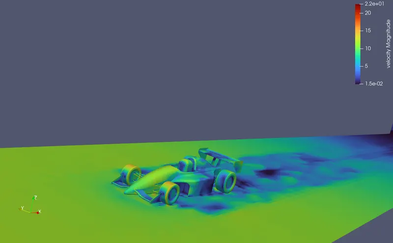
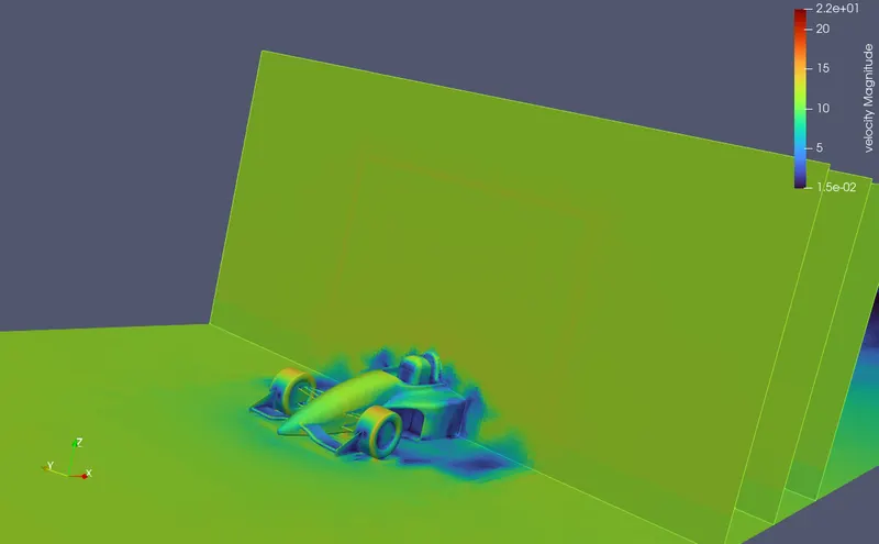
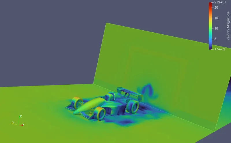
- From the velocity contours we can see that there is less velocity fluctuations around the car going on
- The pressure is distributed more at front than at the rear side
- Here also the front wings produces more negetive lift helping the car stay on the ground tight
- The body faces more drag
- Rear wing also produces negetive lift but its comparitively lesser compared to the frontal wings
- The size of wake region here is less compared to the first case
- Making the car body more streamlined can reduce the drag force and size of the wake region
- If negetive lift is needed at the back the rear wings should be tilted upwards by not causing the drag force to take over
Conclusions
- A trial case setup was done in Phase 1 with coarse mesh and worked fine
- The second phase is set up with more detailing in the mesh and efficient setup
- The Y+ values still have not reached a desired point which needs more computational resources
- Second phase included two cases
- Extracted the velocity contours, Pressure contours,Drag force values and lift force values
- Drag and lift forces goes on fluctuating in a cyclinc manner through time
- Drag force and lift force values can be obtained by running a steady state simulation ,Although the values will be an avaraged one