Week 11 - Final project
Aim:
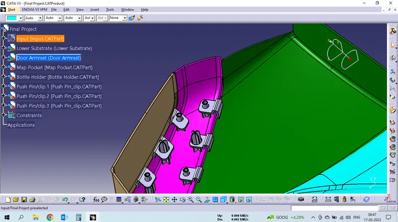
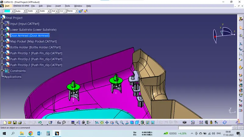
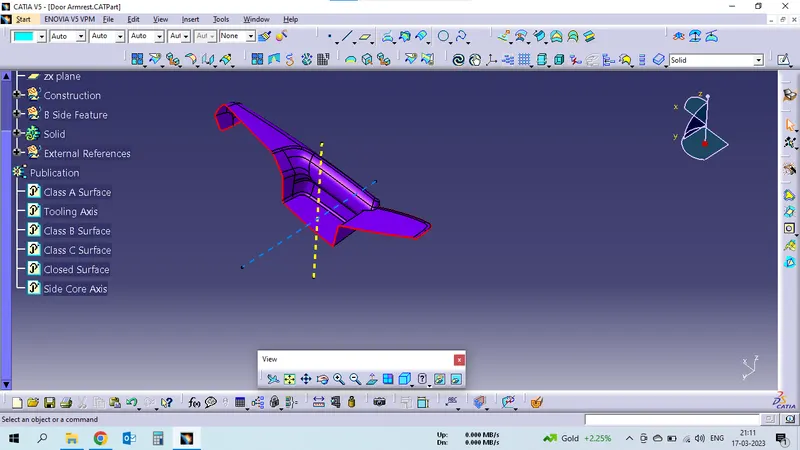
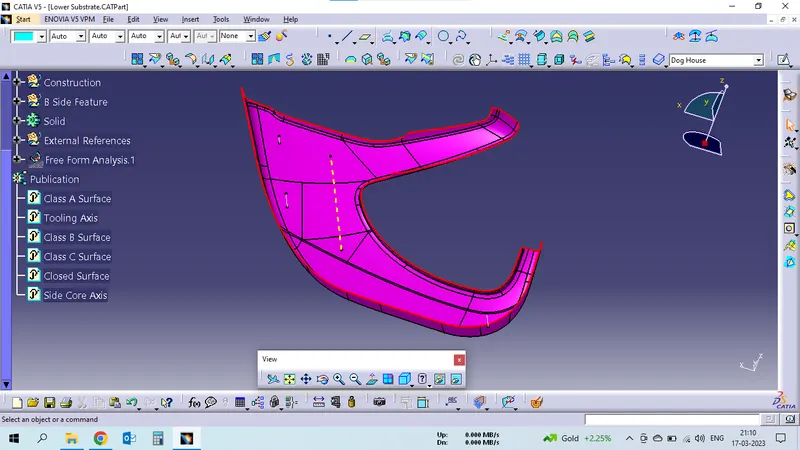
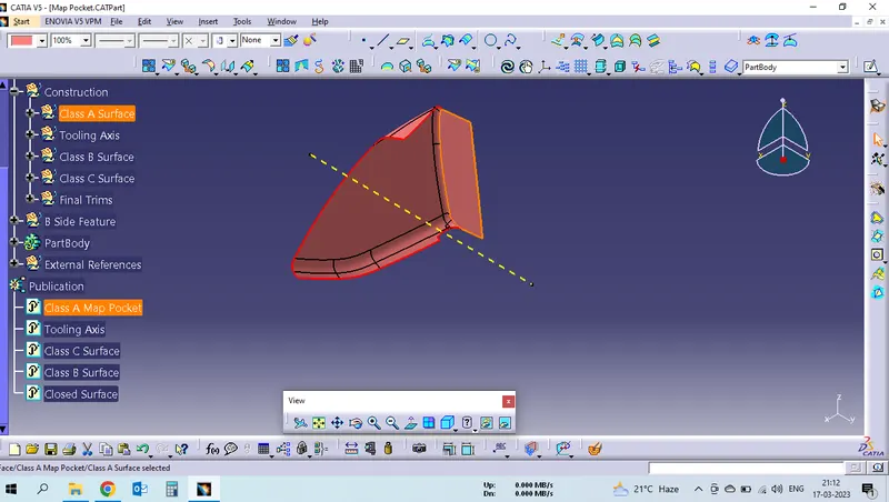
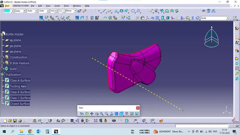
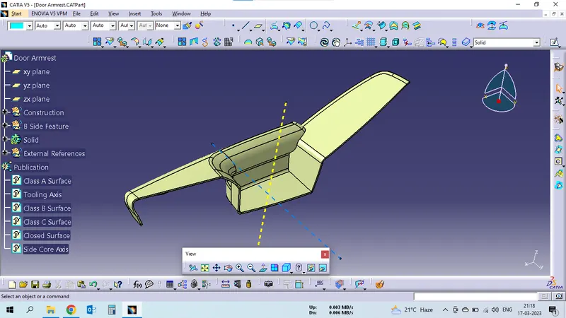
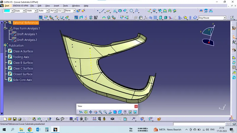
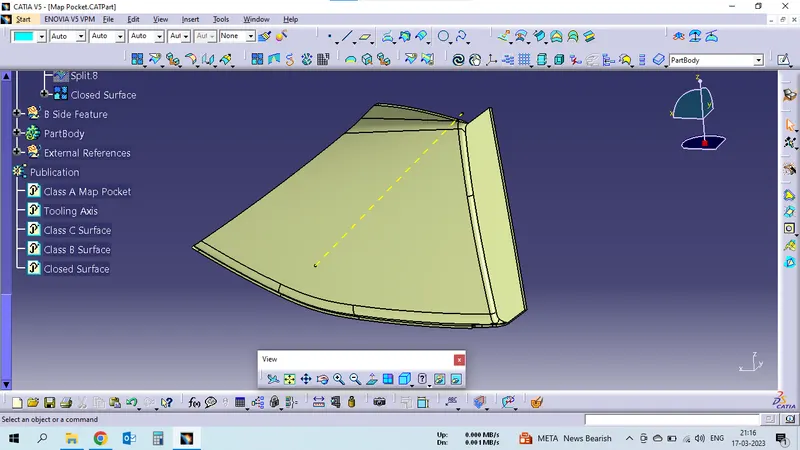
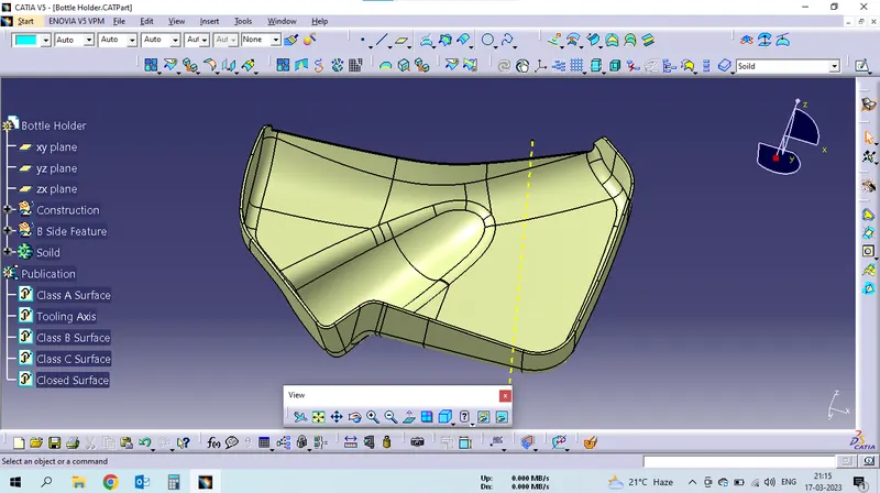
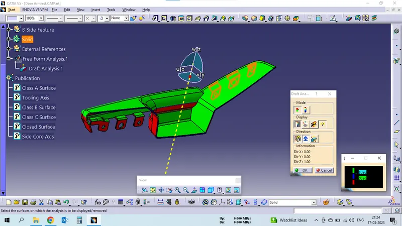
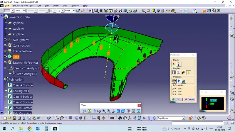
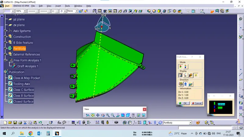
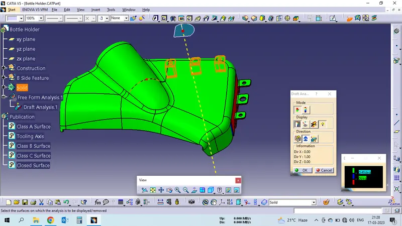
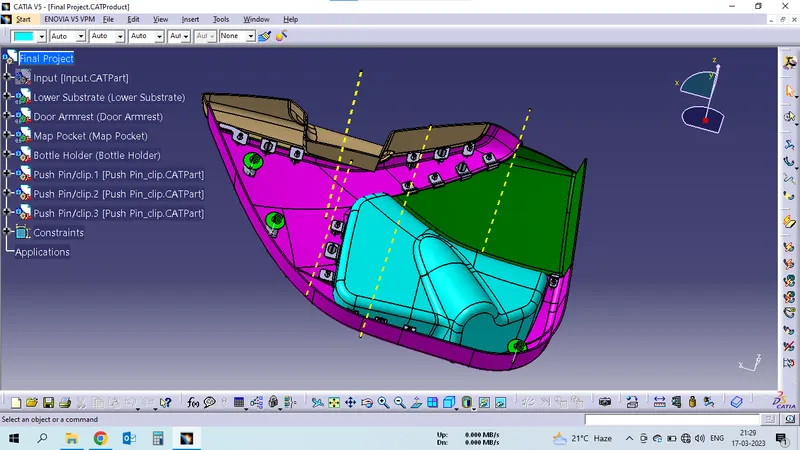
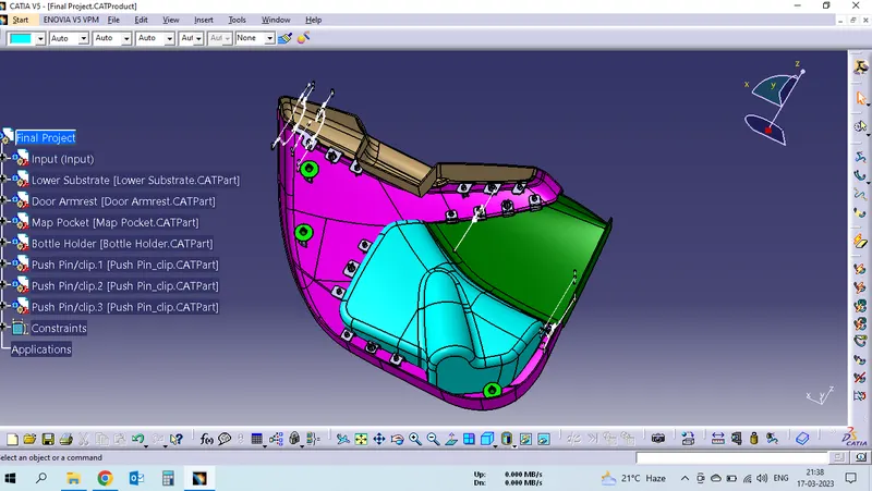
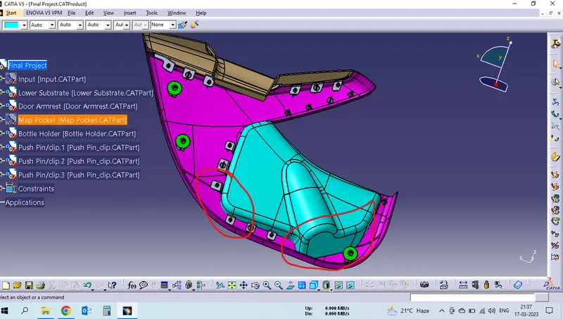
To create a complete solid body of the inner door panel from the provided Class A surfraces. Lower substrate, Door armrest, Map pocket and Bottle Holder are the Class A surfaces given to us and these are the parts that requires to be convertred into solid bodies and assemble them along with the attachment features.
Role of a plastic in automobile industry:
The use of polymers as plastics in the construction of automobiles has continued to grow over the last decades. Nowadays they are the second most commonly found material in cars.
Here are four reasons why plastic is used in car manufacturing:
- Plastics reduce the weight of cars
- Plastics and polymers contribute to the safety of cars
- Plastics help to lower car manufacturing costs
- Polymers advance the design of vehicles
Some of the plastics used in a Car along with area where it is used is shown below:
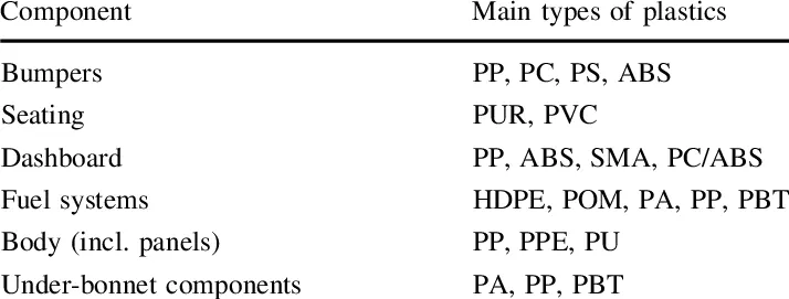
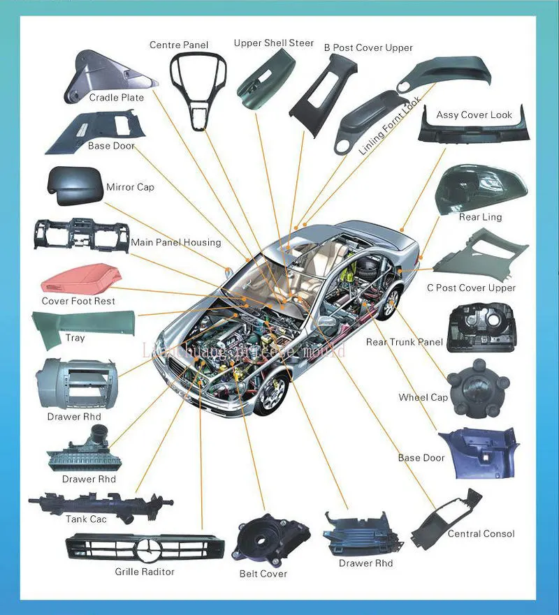
Plastic parts are all individually designed and manufactured by a method called injection moulding and then later using attachment features they are all assembled together to make it a functionable component.
Injection moulding:
Injection moulding is a manufacturing process that allows for parts to be produced in large volumes. It works by injecting molten materials into a mould (or ‘mold’ in the United States). It is typically used as a mass production process to manufacture thousands of identical items. Injection moulding materials include metals, glasses, elastomers and confections, although it is most commonly used with thermoplastic and thermosetting polymers.
The first stage of injection moulding is to create the mould itself. Most moulds are made from metal, usually aluminium or steel, and precision machined to match the features of the product they are to produce.
Once the mould has been created by the mould-maker, the material for the part is fed into a heated barrel and mixed using a helical shaped screw. Heating bands melt the material in the barrel and the molten metal or molten plastic material is then fed into the mould cavity where it cools and hardens, matching the shape of the mould. The cooling time can be reduced through the use of cooling lines that circulate water or oil from an external temperature controller. Mould tools are mounted on plate moulds (or ‘platens’), which open once the material has solidified so that ejector pins can eject the part from the mould.Separate materials can be combined in one part in a type of injection moulding called a two-shot mould. This technique can be used to add a soft touch to plastic products, add colours to a part or produce items with different performance characteristics.
Moulds can be made of single or multiple cavities. Multiple cavity moulds can have identical parts in each cavity or can be unique to create parts of different geometries. Aluminium moulds are not best suited to high volume production or parts with narrow dimensional tolerances since they have inferior mechanical properties and can be prone to wear, deformation and damage due to the injection and clamping forces. While steel moulds are more durable they are also more expensive than aluminium moulds.
The injection moulding process requires careful design, including the shape and features of the part, the materials for the part and the mould and the properties of the moulding machine. As a result, there are various considerations that need to be taken into account when injection moulding.
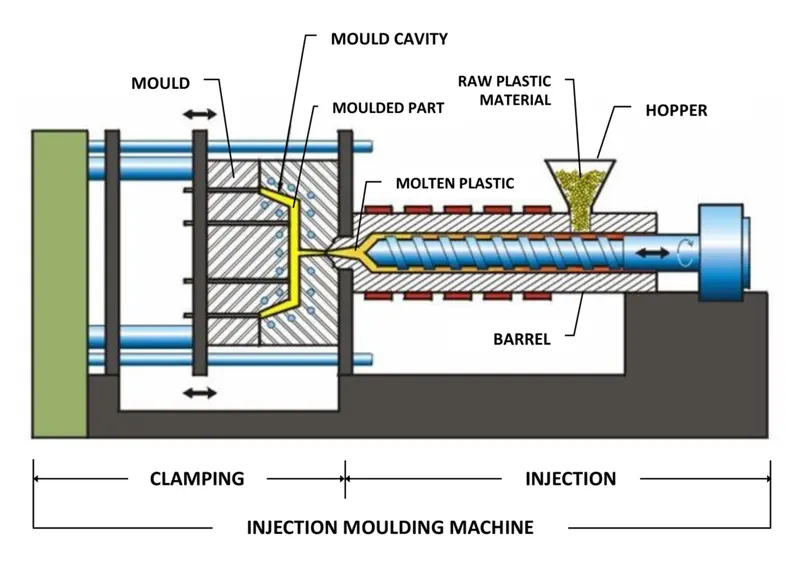
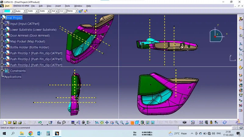
Tooling Direction for Plastic Part
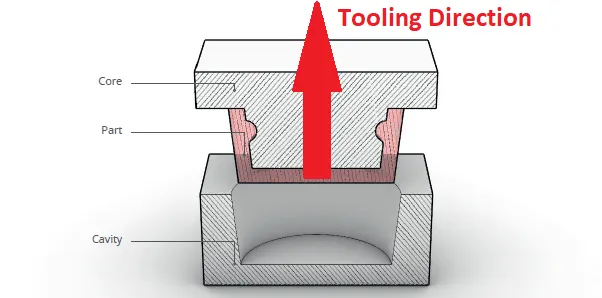
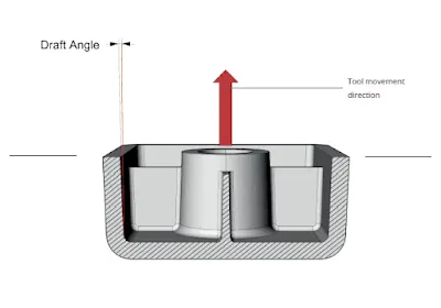
Tooling direction is main consideration for plastic part and mold parts because it defines movement of mold part and possibility of plastic part to come-out from mold part (Core and Cavity).
Tooling Direction:-
- In Molding machine arrangement is given to open the mold along a direction which is known as Tooling Direction.
- In other words. The mold is built from two separate halves (Core and Cavity) and tooling direction basically define the direction of mold pulls apart.
- Tooling direction is known as primary direction.
- Core is the male part of the mould which holds the inner design of the component and the cavity is the female part which holds the outer shape of the component.