Week 11 - Final project
Door trim panel ( Comprises of Armrest, Lower substrate, Map pocket, Bottle holder )
Generally, the part component that we design must be manufacturable and toolable. As we know that in automotives, most interior and some exterior parts are made of plastics. In that approximately 80% of them can be manufactured by Injection molding technique. It have two haves- Core half and Cavity half, in which one is movable and the other one is fixed.
Tooling axis direction-
Tooling axis direction is the direction in which the core and cavity half open and clamp. To be manufacturable, all the faces of the part component must clear with the tooling axis direction. And there are exceptions in which sidecore and lifter axis are used additionally if it's not possible to be cleared with the main tooling axis.
There are three ways to find the tooling axis direction-
- X, Y, Z Axis method ( Global coordinate method )
- Normal to surface method
- Bisecting method
X, Y, Z Axis method is the method by choosing any of the axis from the three ( X, Y, Z ) as the tooling axis direction. In industries, product designers will mostly choose axis method for creating the tooling axis direction of the part component to make the assembly process simple and easier.
Normal to surface method is the method to choose any of the extracted surface as reference, and the axis will be made perpendicular to the reference surface.
Bisecting method is by consecutively bisecting the tapered faces ( Which is neither parallel nor perpendicular ) of the part component for finding the tooling axis direction. And this method will be rarely used by the product designers in industries.
I have found the tooling axis direction of the parts of door trim panel by X, Y, Z Axis method to make the assembly process simple and easier.
Tooling axis direction of Door armrest:
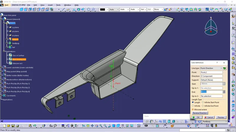
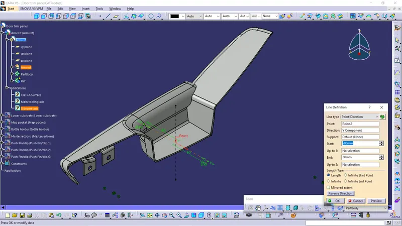
Sidecore axis direction of Armrest:
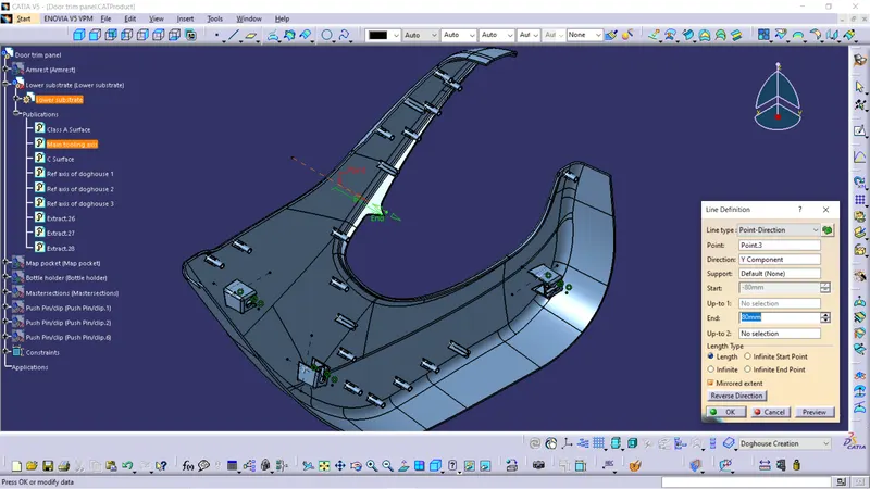
Tooling axis direction of Lower substrate:
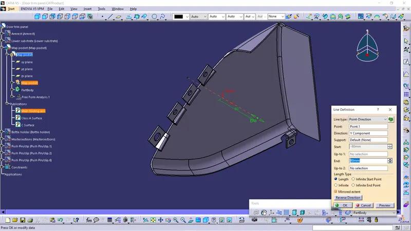
Tooling axis direction of Map pocket:
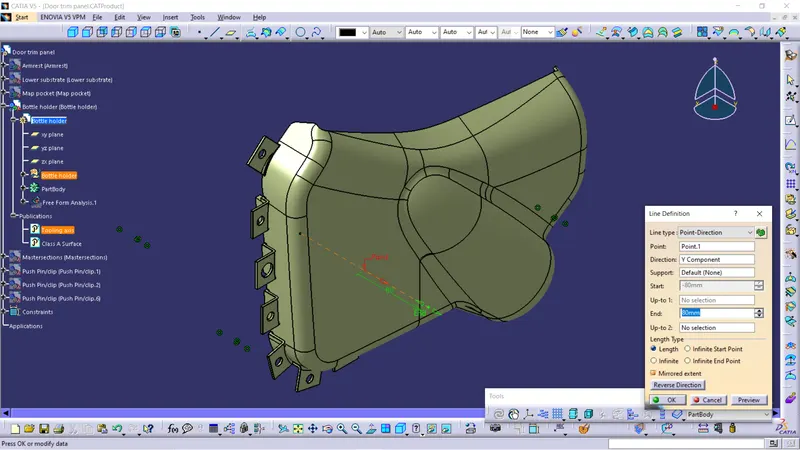
Tooling axis direction of Bottle holder:
Class A Surface-
It is the aesthetic and styling surface that will be given as the input for the product designers for creating the part component. It will be usually designed in the Alias software by Class A designers. If the product designers finds any patch or draft issue in the Class A surface, they will immediately report it to the Class A designer to resolve the issue. At first the product designers will check the quality of the Class A surface and the draft analysis will be made after it.
Every faces of the Class A surface must have a minimum draft of 3 degrees.
Draft analysis-
Draft analysis is the technique that is used to analyze whether the model that is designed can be manufacturable based on the draft condition applied.
Nominal draft value- 3 degree
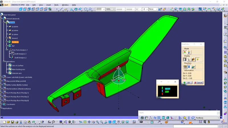
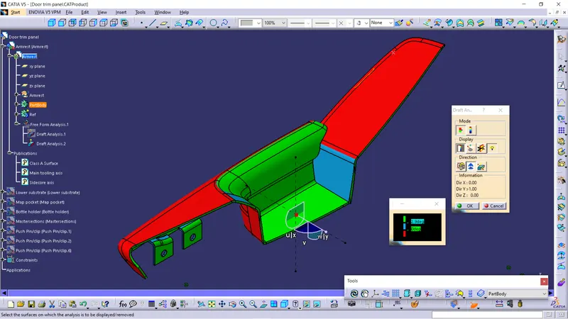
Draft analysis of Armrest ( Class A surface ):
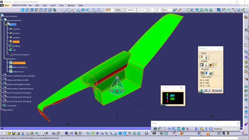
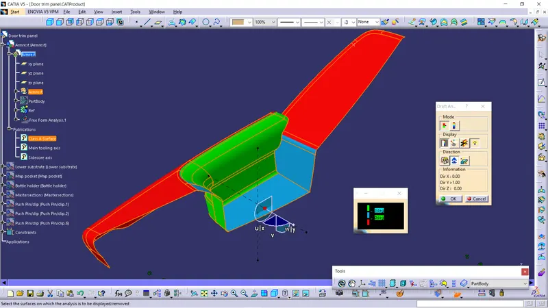
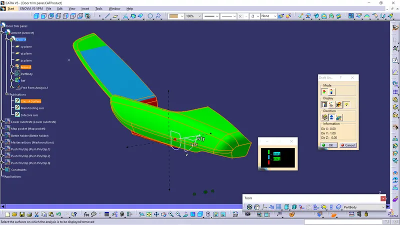
It is impossible to be cleared with main tooling axis alone. So, I have used sidecore axis addtionally.
Draft analysis of Armrest ( Final part ):
Draft analysis of Lower substrate ( Class A ):
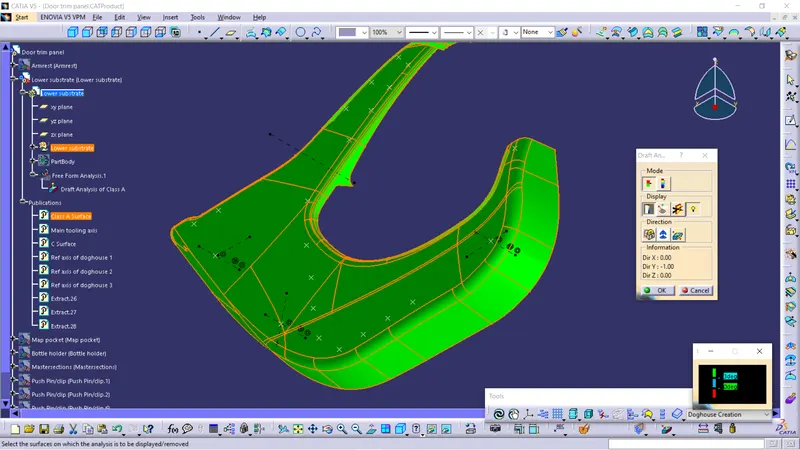
All the faces of the Class A surface have a minimum draft of 3 degrees.
Draft analysis of Lower substrate ( Final part ):
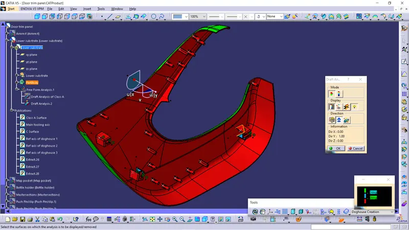
Draft analysis of Map pocket ( Class A ):
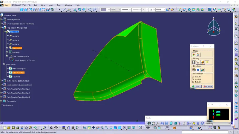
All the faces of the Class A surface have a minimum draft of 3 degrees.
Draft analysis of Map pocket ( Final part ):
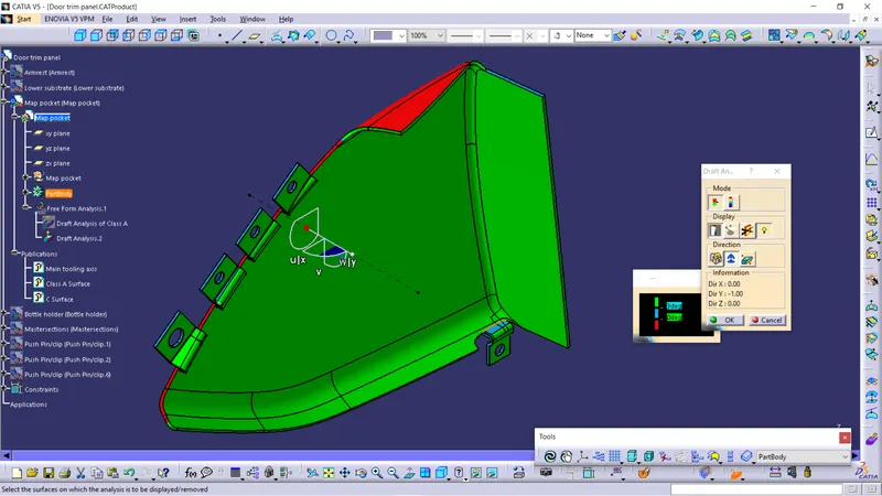
Draft analysis of Bottle holder ( Class A ):
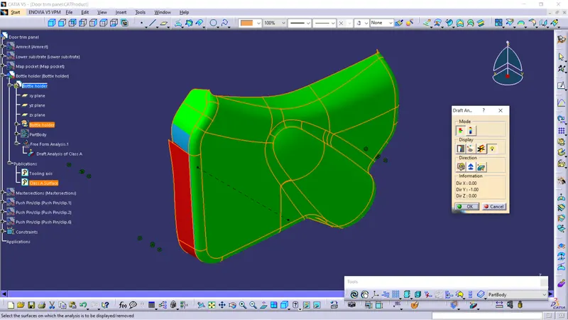
NOTE- There is an red and blue color code in the faces of the bottle holder, this is due to the issue in the input Class A surface. I have consulted it the TSA team.
Draft analysis of Bottle holder ( Final part ):
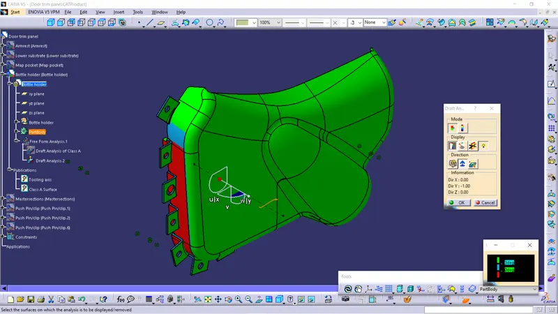
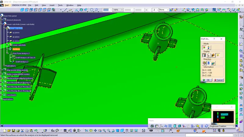
Heatstakes - This is an engineering feature that is used to connect two part components permanently with the help of staking technique. This is as like the plastic welding technique. Usually the heatstakes will be present on the parent part component and the Flanges will be present on the counterpart component ( Child component ). And they will be permanently attached by the staking technique. The heatstakes will have ribs for support to avoid breakage. The flanges will be placed on the ribs of heatstakes.
The heatstake and flange must have a minimum draft of 0.5 degree and fillets of radius 0.25 degree.
Flanges must have a clearance of 0.5mm from the outer surface of heatstakes.
Locators- There are two types of locators- four way and two way locators. They are used to arrest the degree of freedom of the part components. Generally, the locators height must be higher than the height of heatstakes to arrest the degree of freedom ( With a difference of 4- 7mm ).
The locator must have a minimum draft of 0.5 degree and fillet of radius 0.25 degree.
Draft analysis of Locators and Heatstakes:
Doghouse-
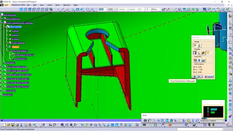
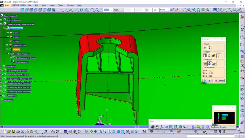
Uses of Doghouse:
- To avoid sinkmarks
- To reduce length issues
- To place the other engineering features perpendicular to the part component
Draft analysis of Doghouse:
Steps that's need to be followed-
- To copy and paste the input surface of the part components in assembly product workbench
- To check the quality of the input surfaces, to resolve if there are any issues
- To create the tooling axis separately for all the parts
- To check the draft analysis of Class A surfaces
- To thicken it by creating the B and C surfaces by following the mastersections
- To check the draft analysis of the base part
- To create the engineering features ( Heatstakes, Locators, Doghouse ) by following the mastersections and design rules
- To assemble all the part components and input push pins by providing suitable constraints ( Coincidence, Offset, Contact, Fix constraints )
- To save by save management.