Week 11 - Final project
Challenge: Development of a Door Trim panel
Creation of CAD model considering following inputs as like in OEM and tier1 companies
- a) Class A surface
- b) Nominal thickness : Refer master sections
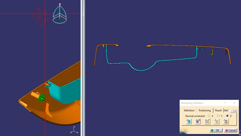
- c) Attachment strategy :
Find a attachment strategy for the door panel complete work.
Use Push pin with Dog house for Lower substrate – Door panel attachment
Use heat stakes for part to part attachment.
Ans:
Given challenge has 4 parts.
1. Arm Rest
2. Lower Substrate
3. Map Pocket
4. Bottle Holder
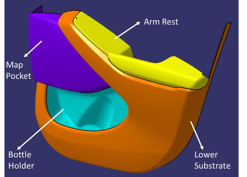
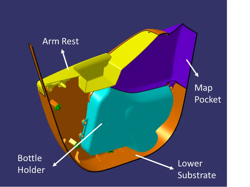
Input
Given Input file consist of Class-A surfaces of all the sub parts & Master section, which provide the information about B-side features & flange locations.
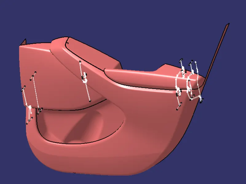
The profiles shown in the above picture refers to Master sections
1. Arm Rest
Class A Surface
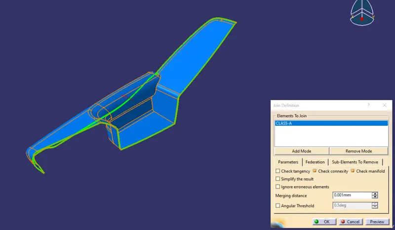
To ensure the connectivity between the surfaces, all surfaces joined using join.
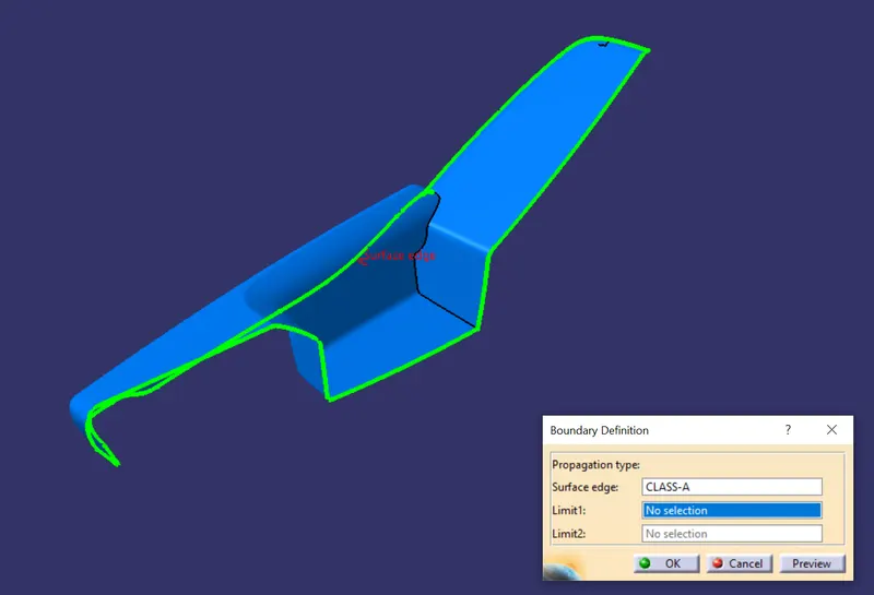
Using boundary command Class-A surface checked for unnecessary open profiles between the surfaces.
Tooling Axis
To create a tooling axis the below method need to be followed.
a. Base surface extracted & a point created at the centre of the surface.
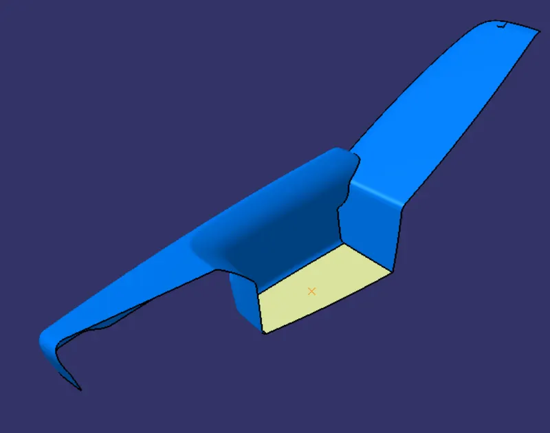
b. Axis system created at the point.
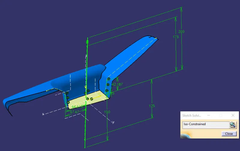
c. Position sketch created and the class A surface intersected with YZ plane.
d. Two line created along the incline lines & a bisecting line is created.
e. This is the Tooling Clearing in Z-direction.
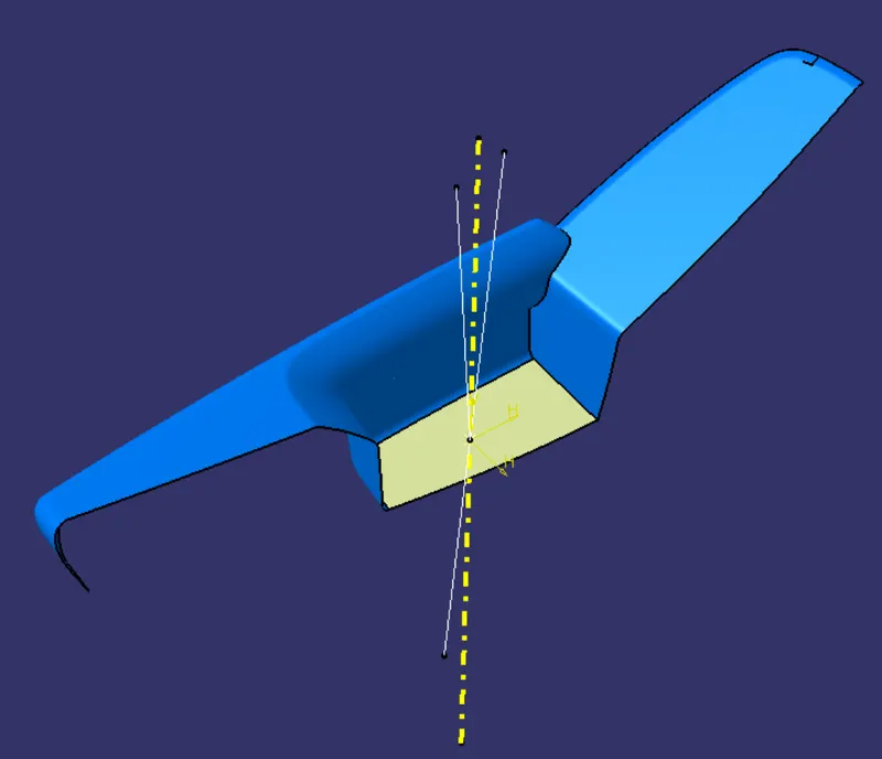
A bisecting line is created at the centre point using the bisecting lines which are created in position sketches 1&2.
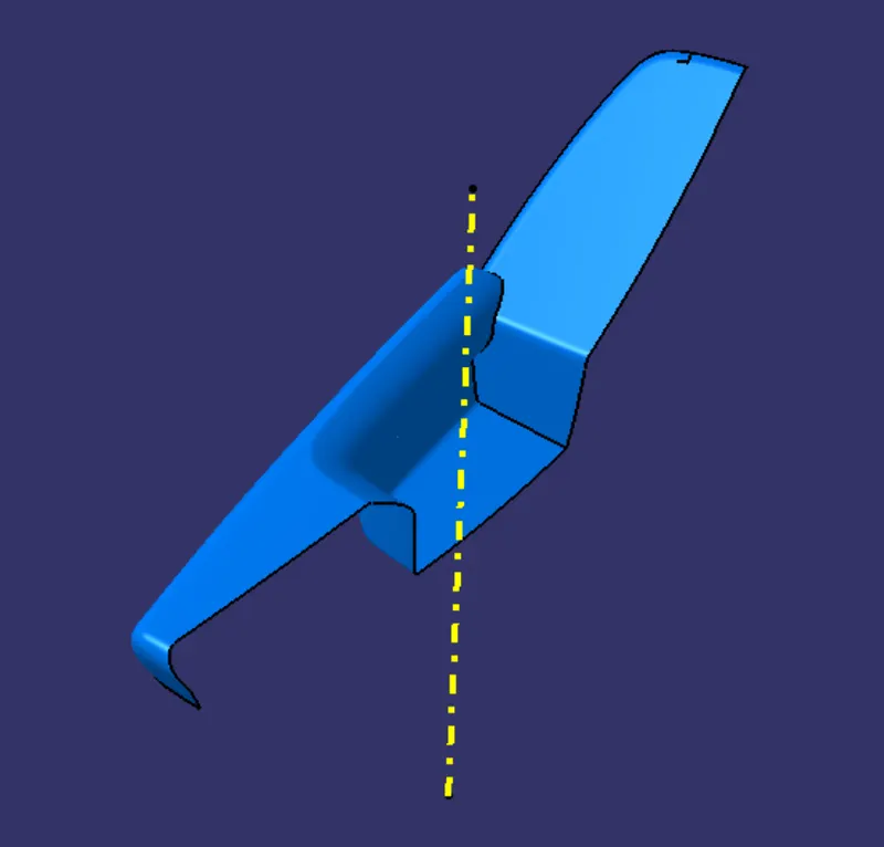
This is the Tooling Axis for the model.
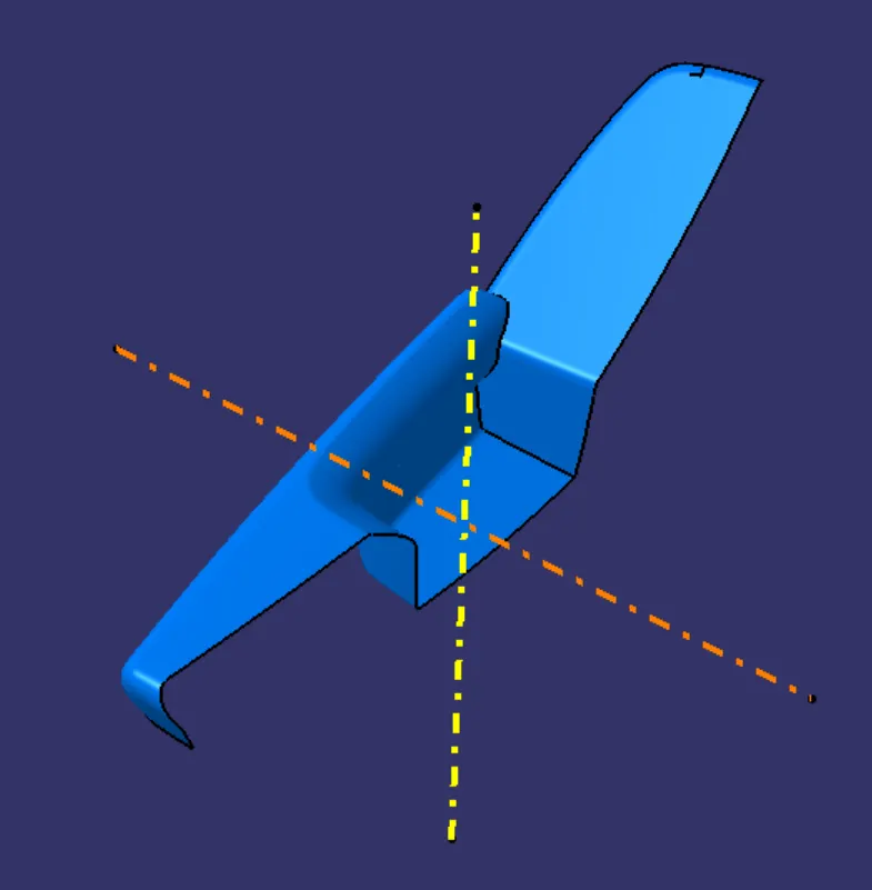
Lifter Axis is created perpendicular to Tooling Axis.
Draft Analysis on Class A surface
Few steps need to be followed to perform draft analysis.
Step 1:
- View --> Customise view parameters --> Mesh --> Material --> Ok.
- The go to Insert --> Analysis --> Feature Draft Analysis
- Click on compass from the direction, drag & drop compass on the tooling axis in such a way that Z axis to be along the tooling axis.
- Lock the compass using lock command from direction.
- Click on the surface to see the results.
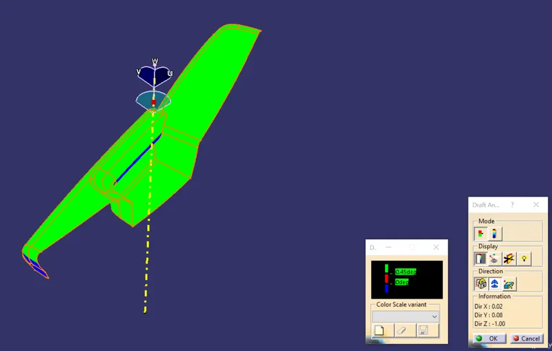
Draft Analysis on Class-A surface along Tooling Axis.
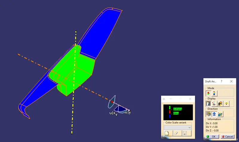
Draft Analysis on Class-A surface along Lifter Axis.
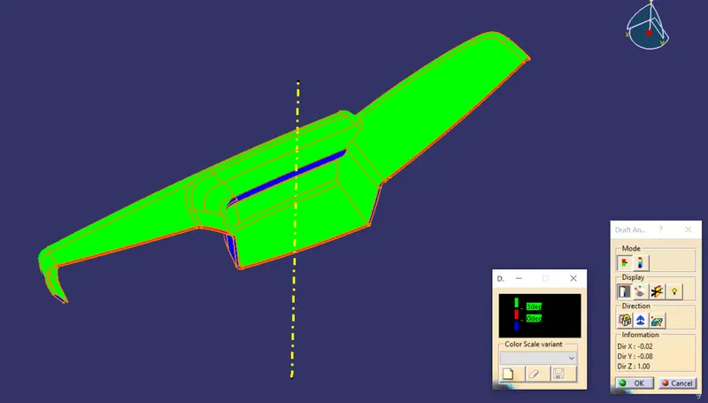
Draft Analysis on Final Trim along Tooling Axis.
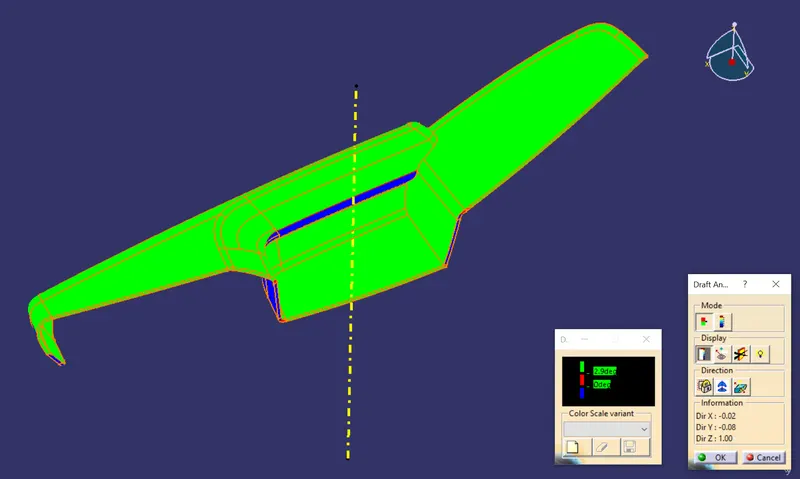
Most of the surfaces clearing tooling at draft angle of 2.9 degrees.
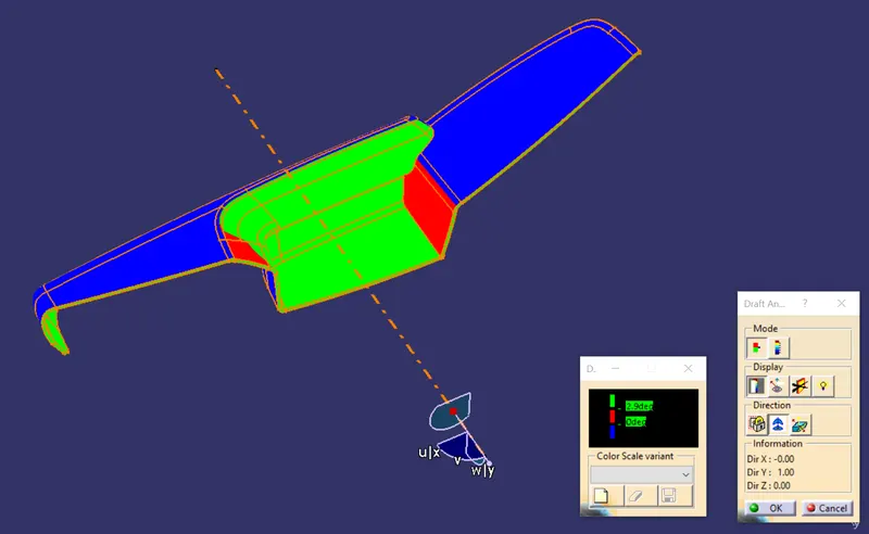
Draft Analysis on Final Trim surface along Lifter Axis.
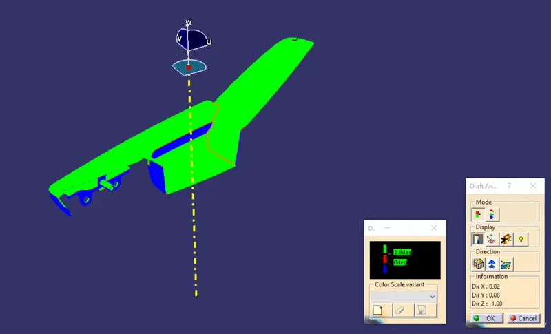
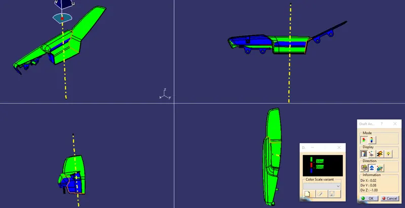
Draft Analysis on Arm Rest with B-side features along Tooling Axis.Most of the surfaces clearing tooling at draft angle of 2.9 degrees.
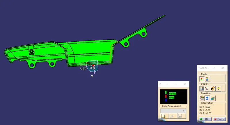
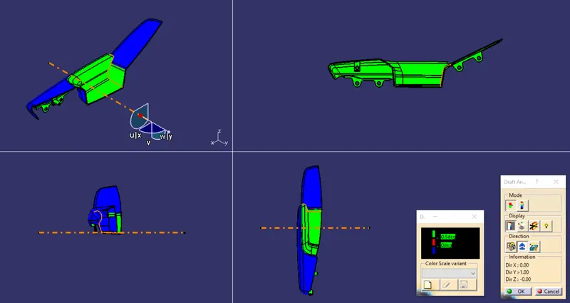
B-side features clearing Lifter Axis.
Class B Surface
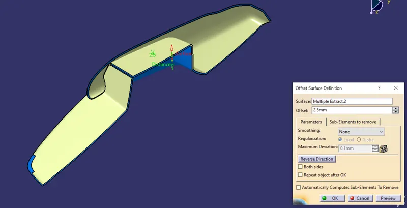
Class-A is divided into two parts, both parts are off-set separately. Using commands like Blend, Multi Section Surface & Fill, all the gaps were filled.
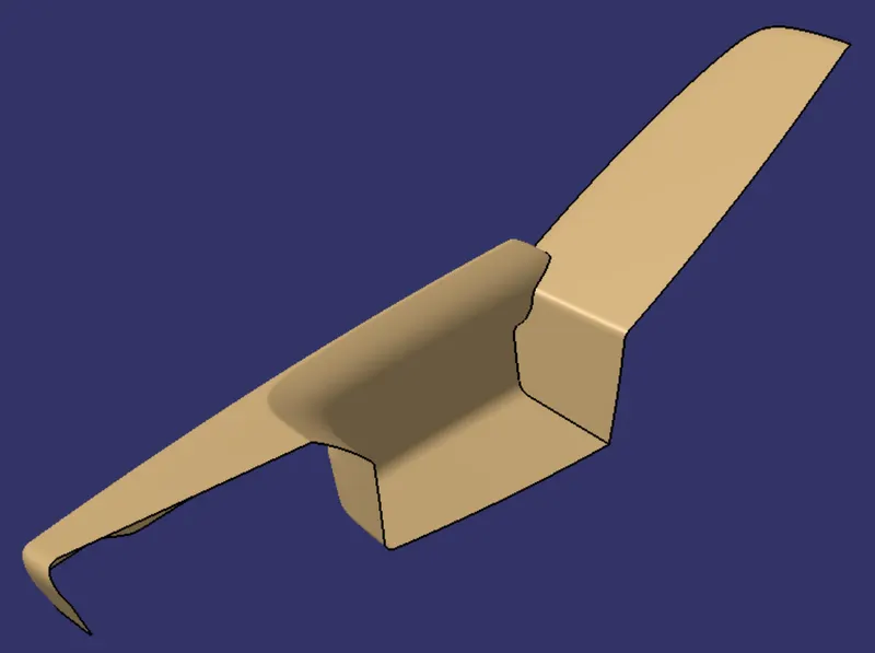
Class-B Surface
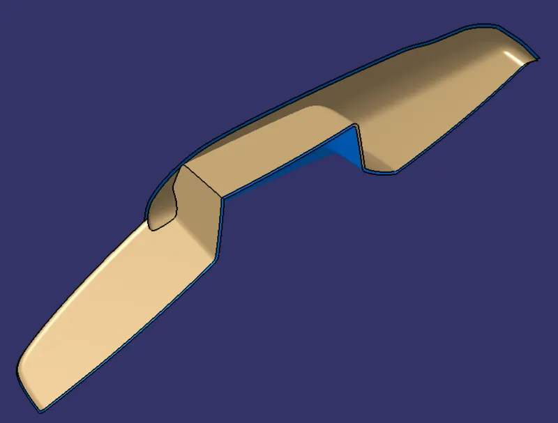
Class-A & Class-B surfaces.
Class-C Surface
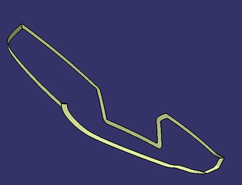
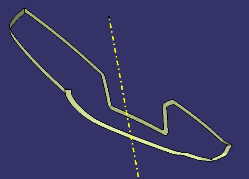
Class-C is created by drafting the edges of Class-A along Tooling Axis direction.
Class-A&C
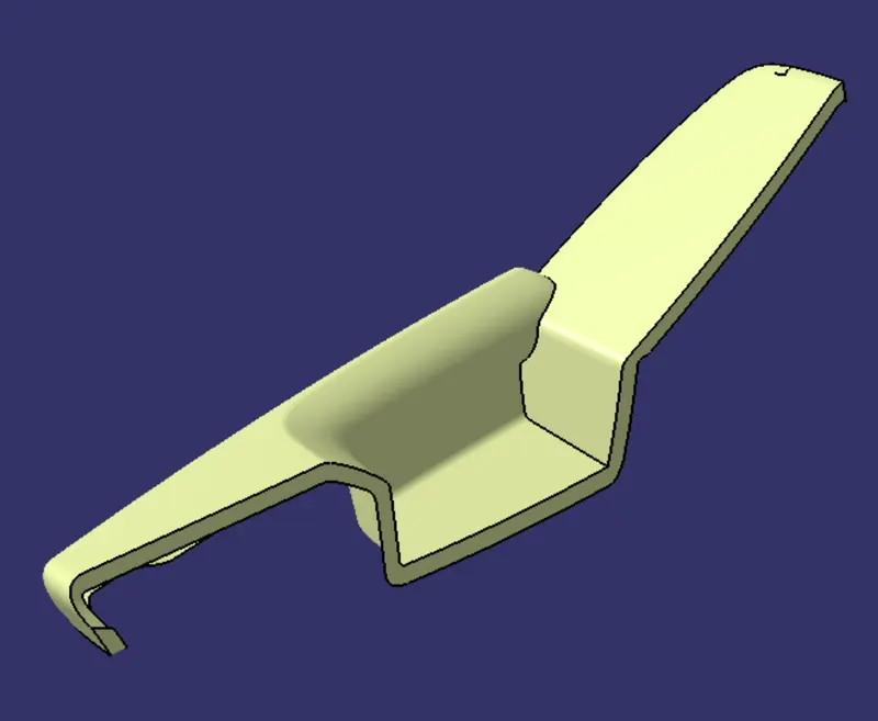
Class-A&C are joined to perform Final Trim.
Final Trim
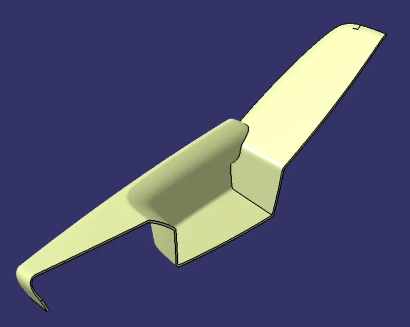
Class-B surface extrapolated & trimmed with Class-A&C, to get Final Trim.
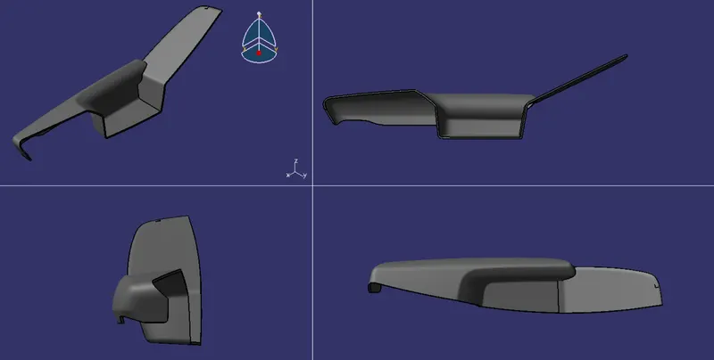
Close Body of Final Trim
B-Side Features
B Side features such as flanges, fixing provisions were created using Master Sections.
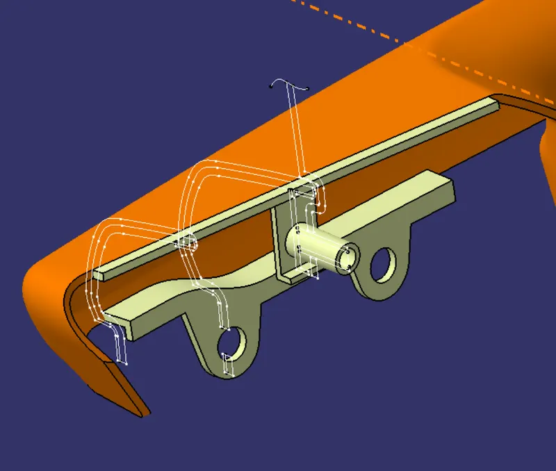
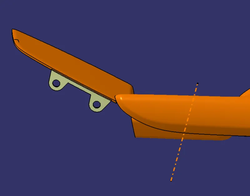
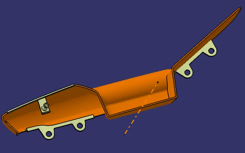
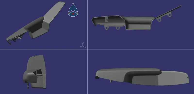
Plastic Material properties are applied to the Arm Rest.
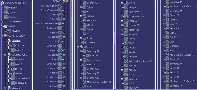
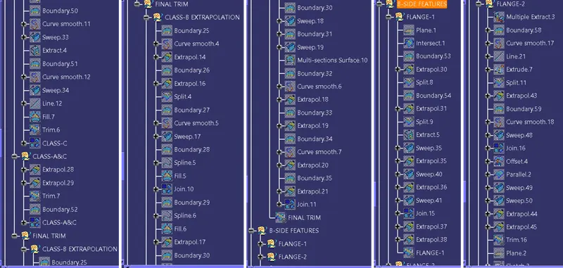
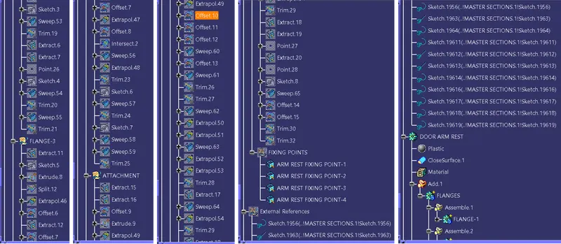
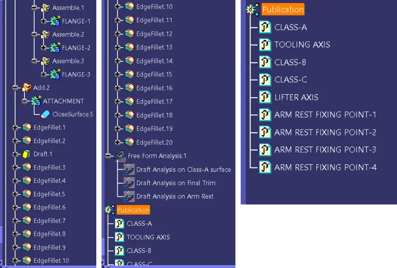
Arm Rest Product Tree
2.Map Pocket
Class A Surface
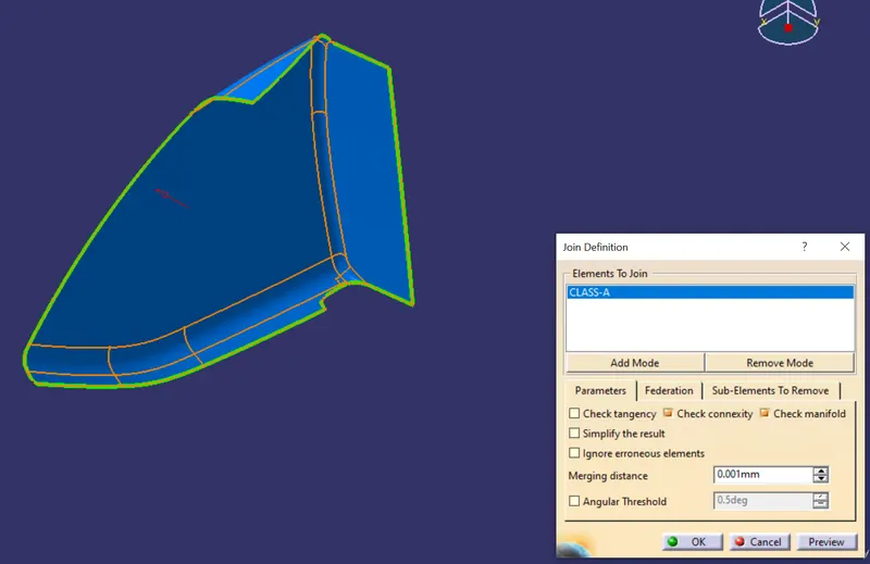
To ensure the connectivity between the surfaces, all surfaces joined using join.
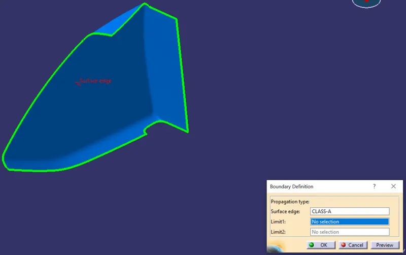
Using boundary command Class-A surface checked for unnecessary open profiles between the surfaces.
Tooling Axis
To create a tooling axis the below steps need to be followed
Step 1:
a. Create a point at Centre of Gravity (CG) of the surface
b. Follow the instructions to create a point at CG
Go to Measure tool bar
Measure --> Measure inertia --> Create Geometry --> Non-associative geometry --> Centre of Gravity --> Ok --> OK.
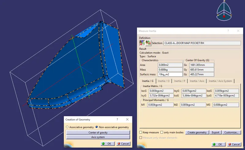
A point is created at CG of the surface.
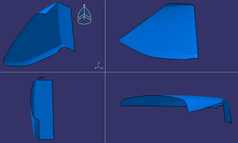
Tooling direction checked for X,Y&Z axis. Tooling can clear all the features of the surfaces in Y-direction.
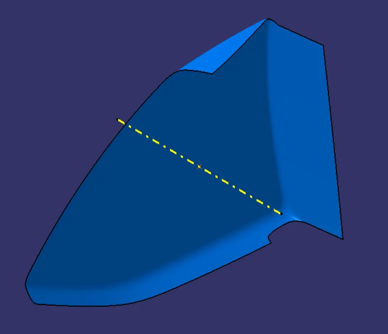
Tooling Axis is created at the point along Y-direction.
Draft Analysis on Class A surface
Few steps need to be followed to perform draft analysis.
Step 1:
- View --> Customise view parameters --> Mesh --> Material --> Ok.
- The go to Insert --> Analysis --> Feature Draft Analysis
- Click on compass from the direction, drag & drop compass on the tooling axis in such a way that Z axis to be along the tooling axis.
- Lock the compass using lock command from direction.
- Click on the surface to see the results.
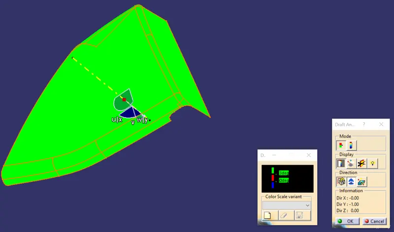
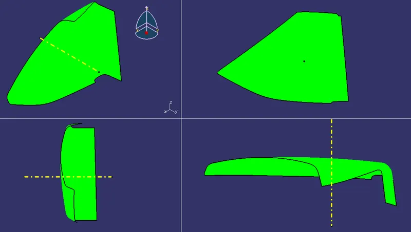
Draft Analysis on Final Trim along Tooling Axis.
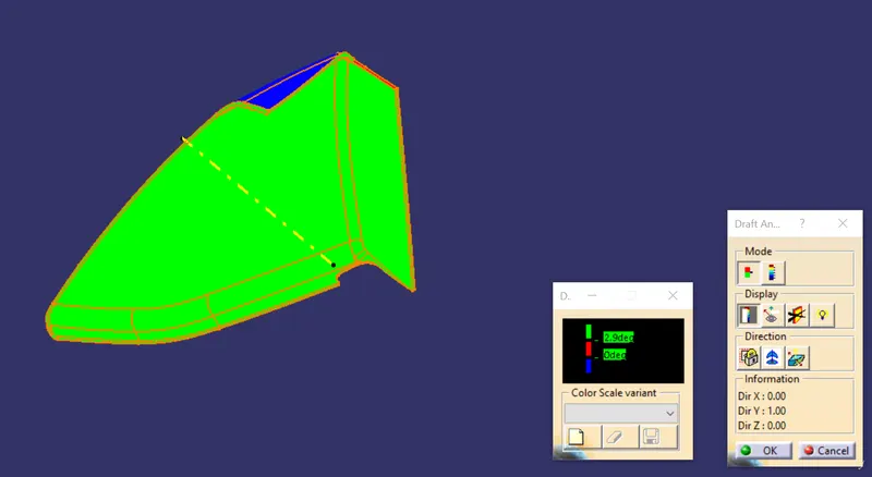
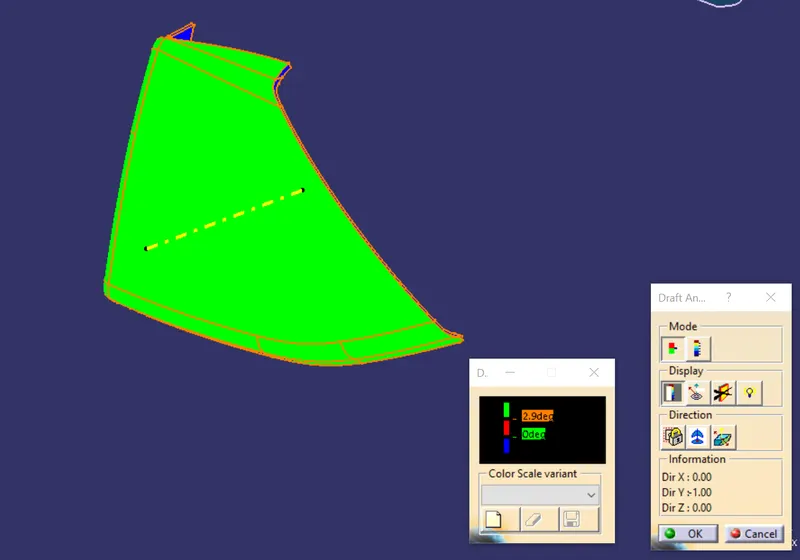
Most of the surfaces clearing tooling at draft angle of 2.9 degrees.
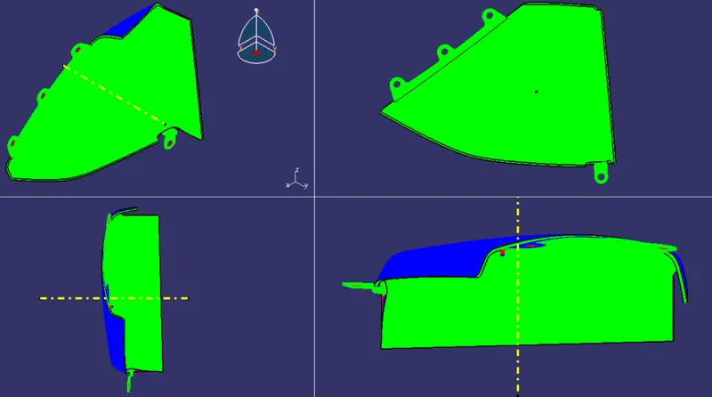
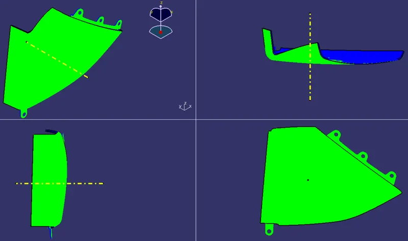
Draft Analysis on Map Pocket with B-side features along Tooling Axis.Most of the surfaces clearing tooling at draft angle of 2.9 degrees.
Class B Surface
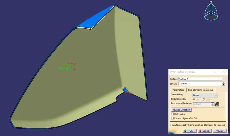
Class-A is off-set separately by thickness.
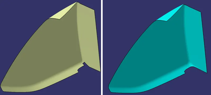
Edges extrapolated, trimmed & fillet is applied on the corner.
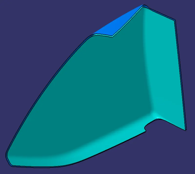
Class-A & Class-B surfaces.
Class-C Surface
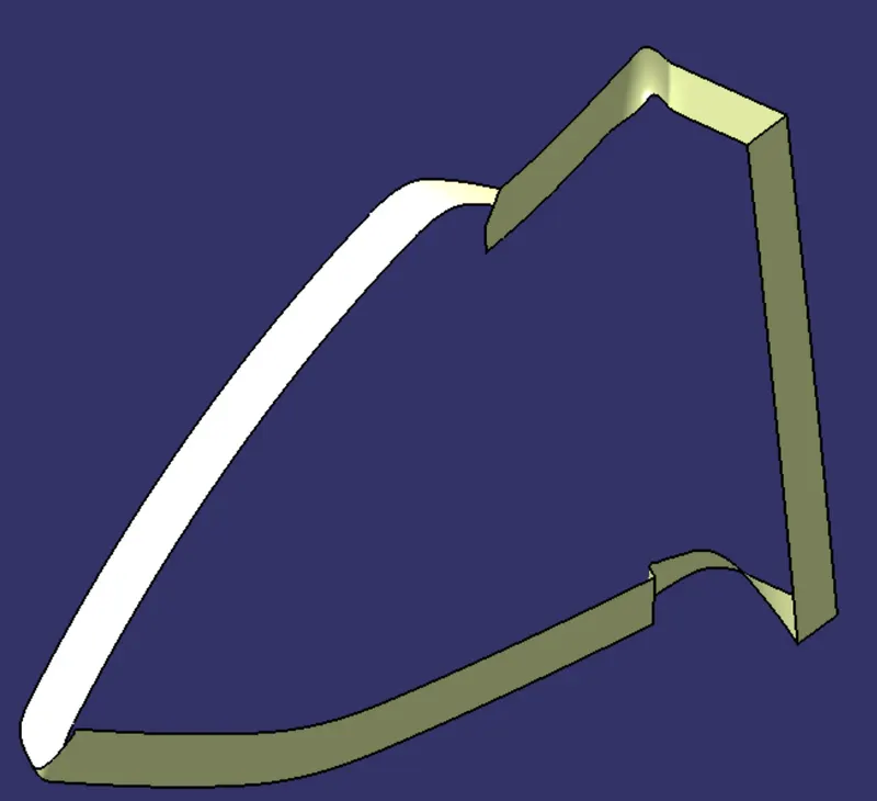
Class-C is created by drafting the edges of Class-A along Tooling Axis direction.
Class-A&C
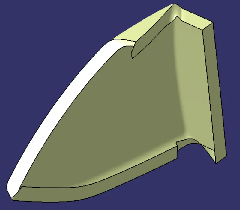
Class-A&C are joined to perform Final Trim.
Final Trim
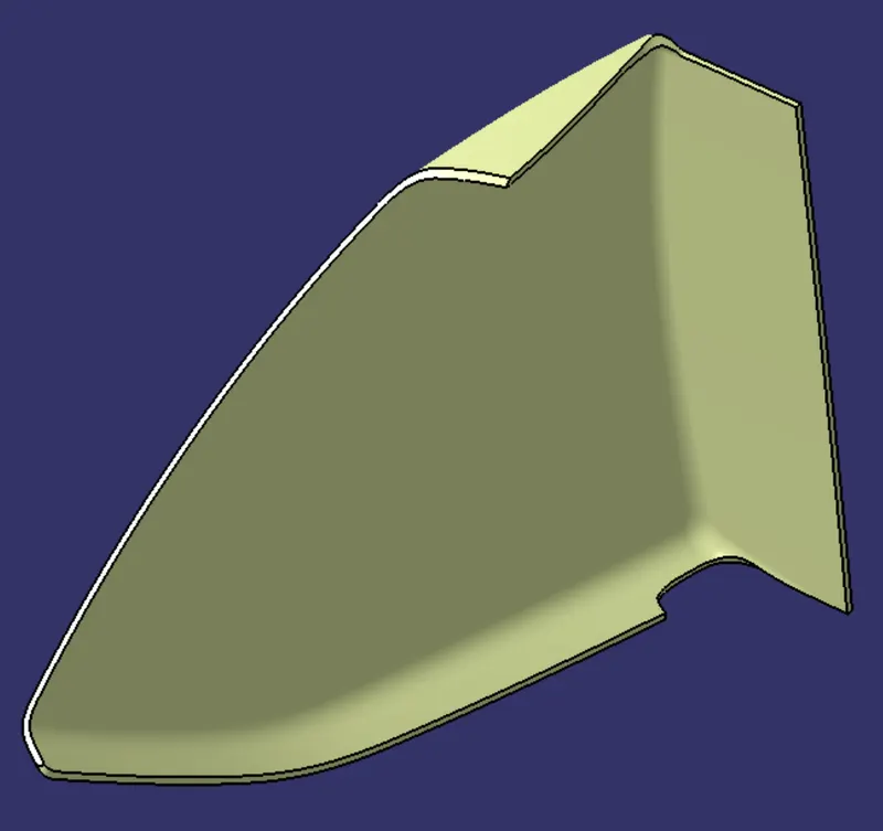
Class-B surface extrapolated & trimmed with Class-A&C, to get Final Trim.
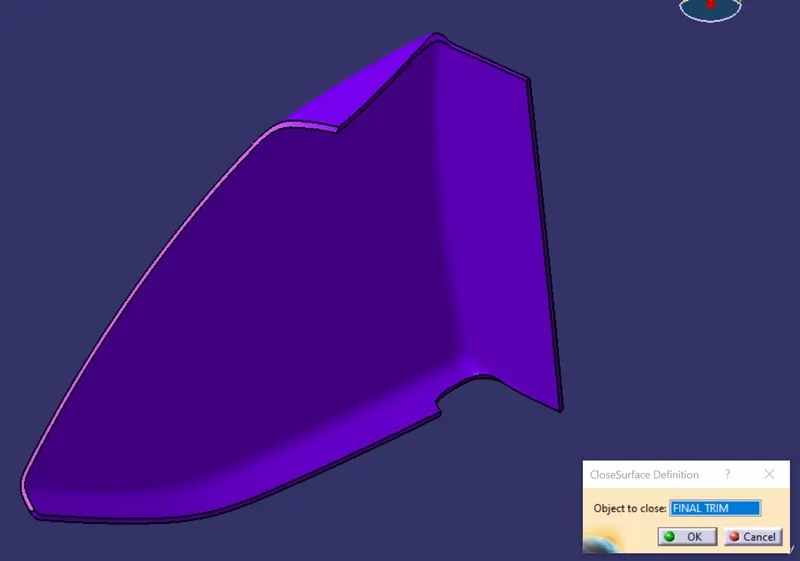
Close Body of Final Trim
B-Side Features
B Side features such as flanges, fixing provisions were created using Master Sections.
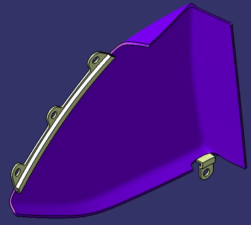
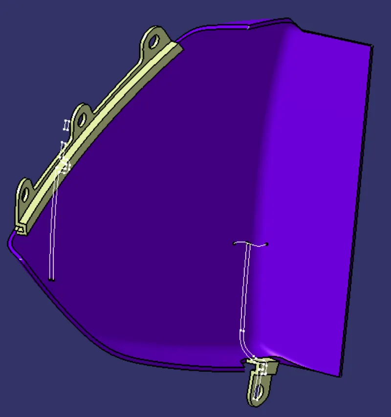
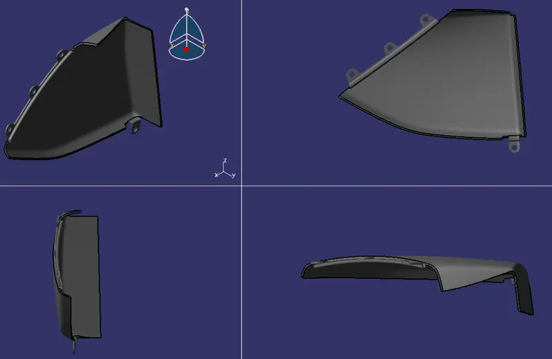
Plastic Material properties are applied to the Map Pocket.
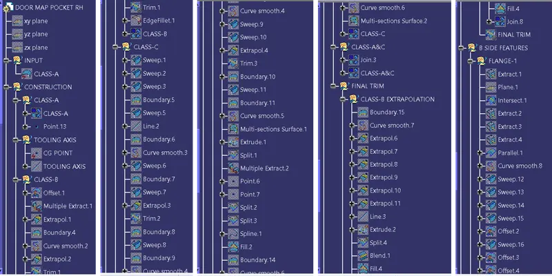
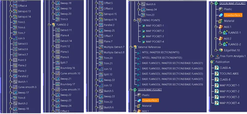
Map Pocket Product Tree
3. BOTTLE HOLDER
Class A Surface
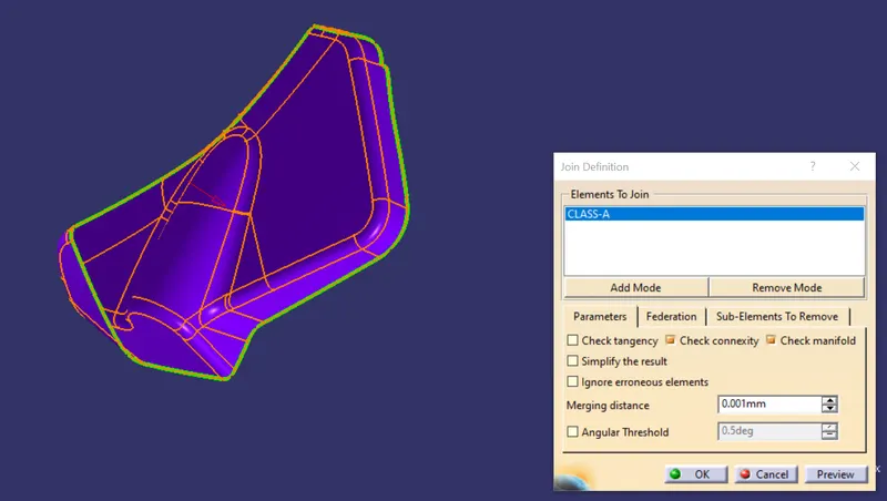
To ensure the connectivity between the surfaces, all surfaces joined using join.
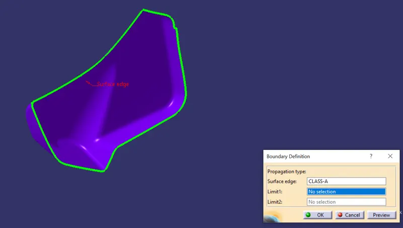
Using boundary command Class-A surface checked for unnecessary open profiles between the surfaces.
Tooling Axis
To create a tooling axis the below steps need to be followed
Step 1:
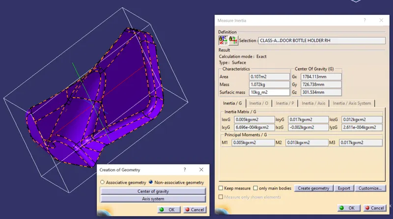
a. Create a point at Centre of Gravity (CG) of the surface
b. Follow the instructions to create a point at CG
Go to Measure tool bar
Measure --> Measure inertia --> Create Geometry --> Non-associative geometry --> Centre of Gravity --> Ok --> OK.
This is the Tooling Axis for the model.
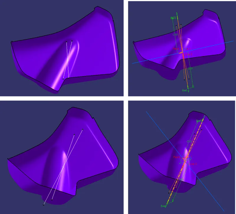
Few lines created in other direction to create Tooling Axis.
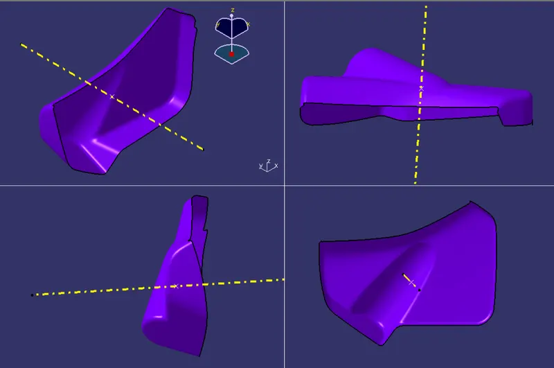
In this direction most of the surfaces will clear the tooling.
Draft Analysis on Class A surface
Few steps need to be followed to perform draft analysis.
Step 1:
- View --> Customise view parameters --> Mesh --> Material --> Ok.
- The go to Insert --> Analysis --> Feature Draft Analysis
- Click on compass from the direction, drag & drop compass on the tooling axis in such a way that Z axis to be along the tooling axis.
- Lock the compass using lock command from direction.
- Click on the surface to see the results.
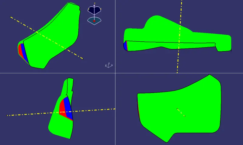
Draft Analysis on Class-A surface along Tooling Axis.
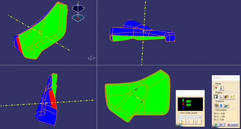
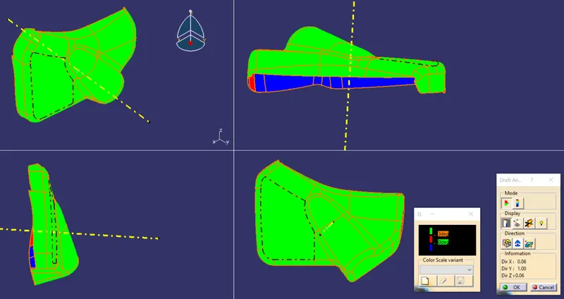
Draft Analysis on Final Trim along Tooling Axis.
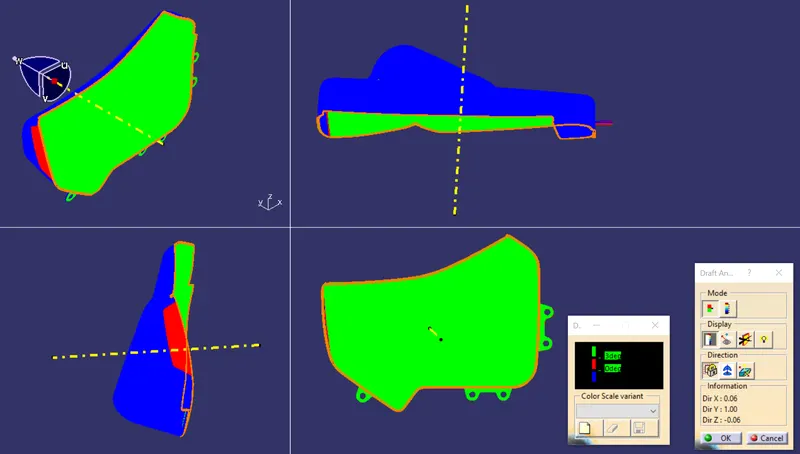
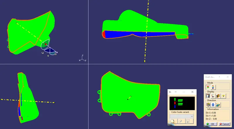
Draft Analysis on Bottle Holder with B-side features along Tooling Axis.
Class B Surface
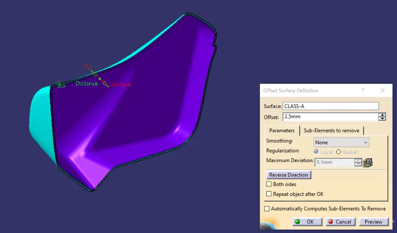
Class-B is created by off-set Class-A.
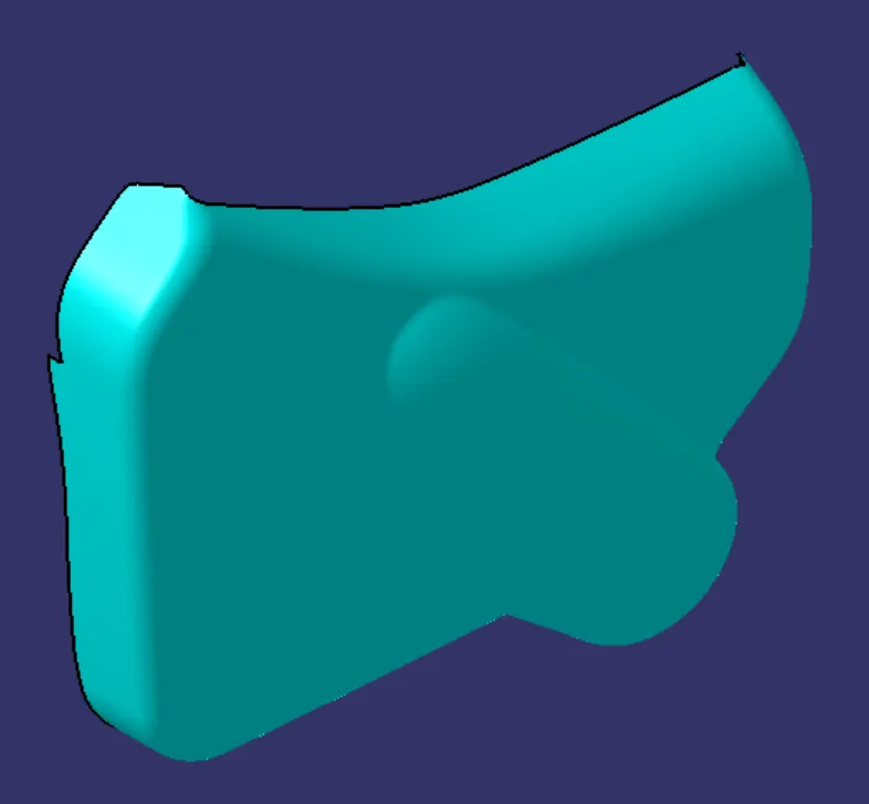
Class-B Surface
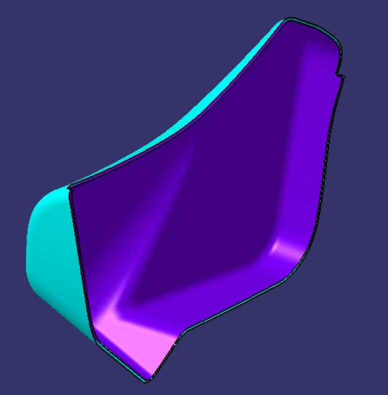
Class-A & Class-B surfaces.
Class-C Surface
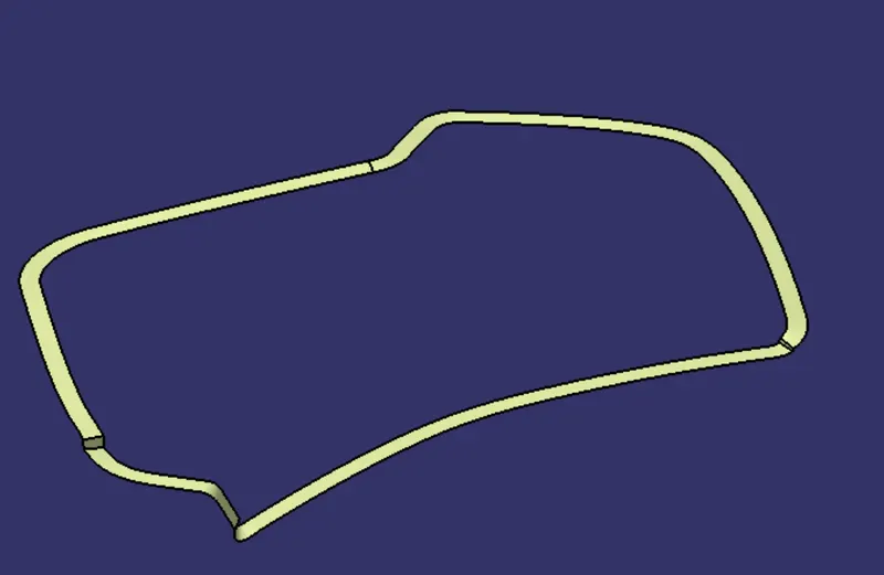
Class-C is created by drafting the edges of Class-A along Tooling Axis direction.
Class-A&C
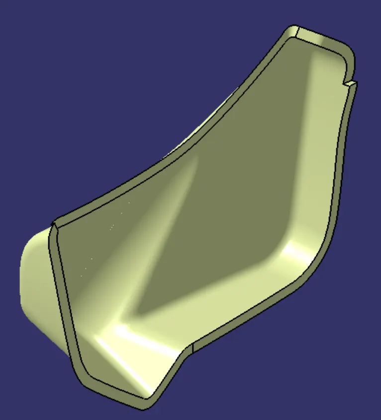
Class-A&C are joined to perform Final Trim.
Final Trim
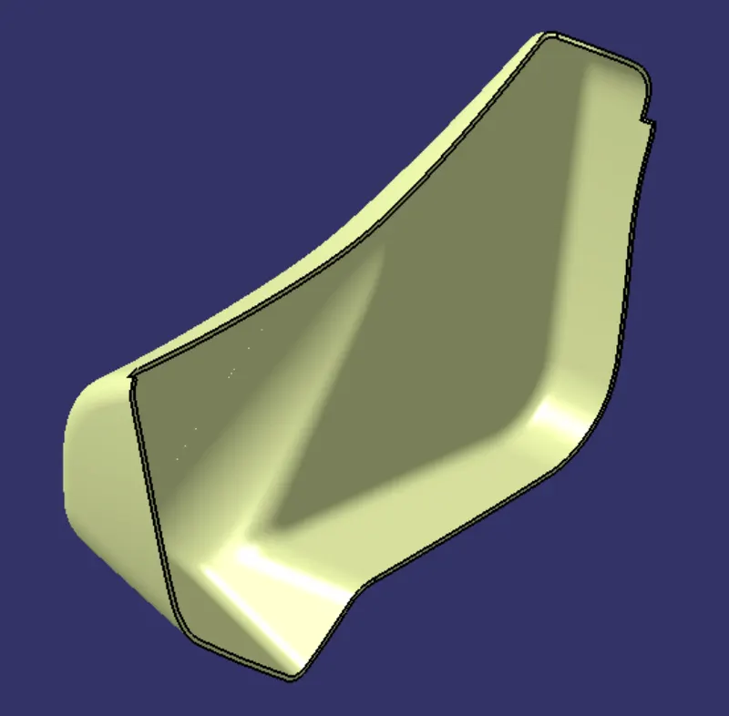
Class-B surface extrapolated & trimmed with Class-A&C, to get Final Trim.
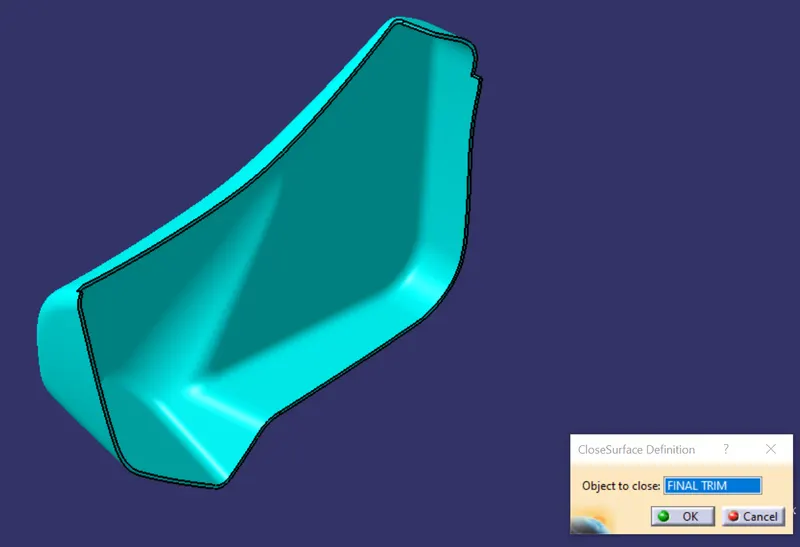
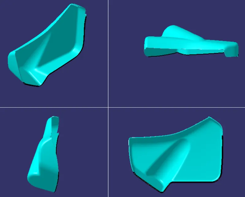
Close Body of Final Trim
B-Side Surface
Fixing provisions were created to fix Bottle Holder to Lower Substrate.
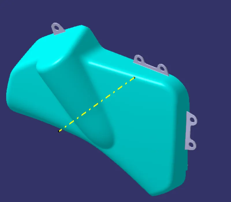
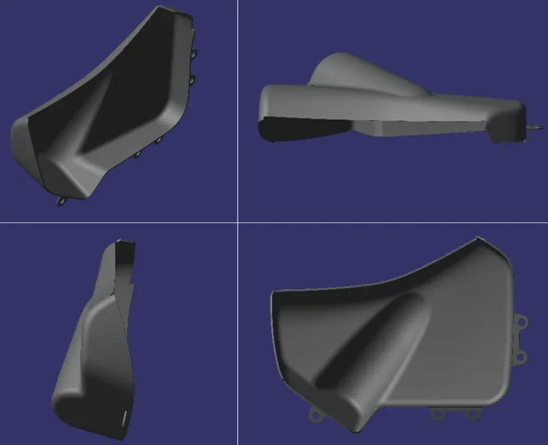
Plastic Material properties are applied to the Bottle Holder.
Bottle Holder Product Tree
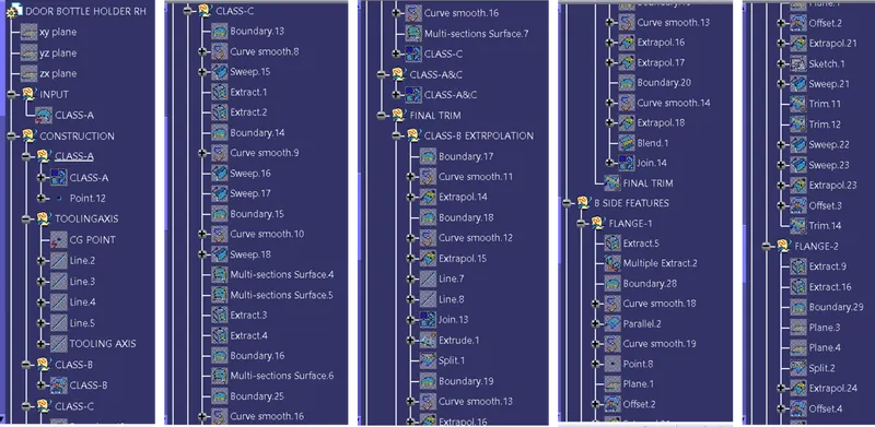
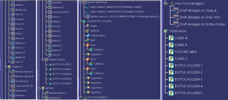
4. Lower Substrate
Class A Surface
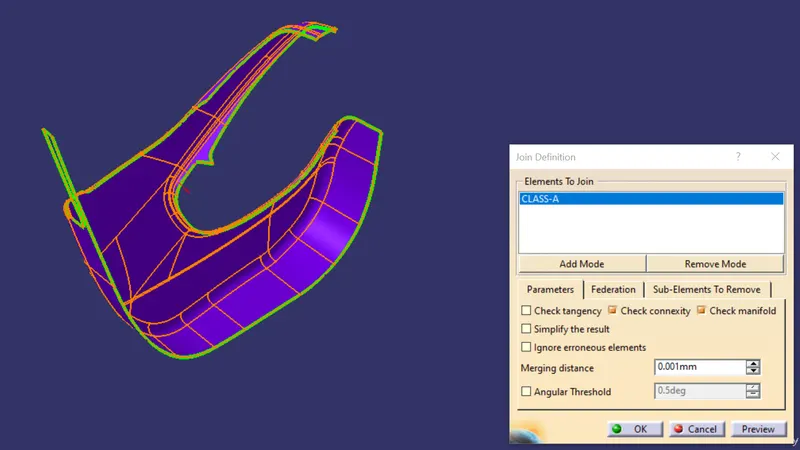
To ensure the connectivity between the surfaces, all surfaces joined using join.
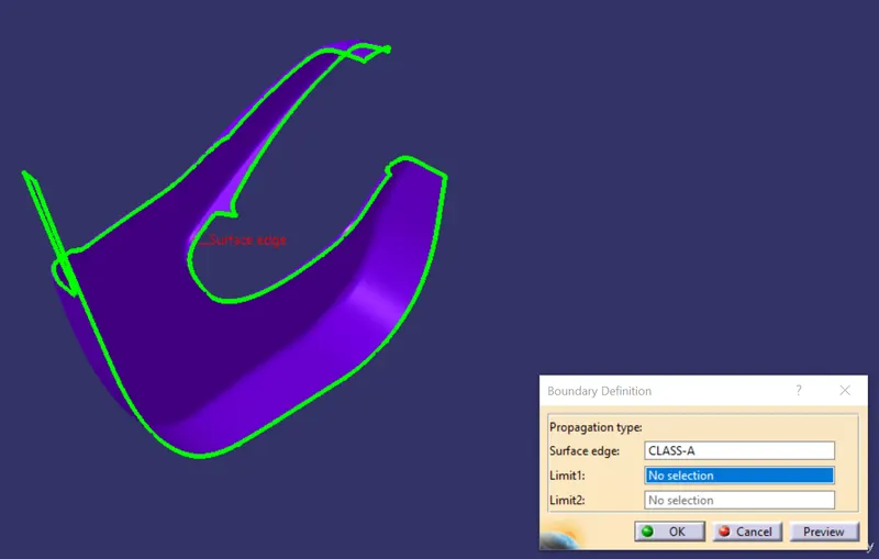
Using boundary command Class-A surface checked for unnecessary open profiles between the surfaces.
Tooling Axis
To create a tooling axis the below steps need to be followed
Step 1:
a. Create a point at Centre of Gravity (CG) of the surface
b. Follow the instructions to create a point at CG
Go to Measure tool bar
Measure --> Measure inertia --> Create Geometry --> Non-associative geometry --> Centre of Gravity --> Ok --> OK.
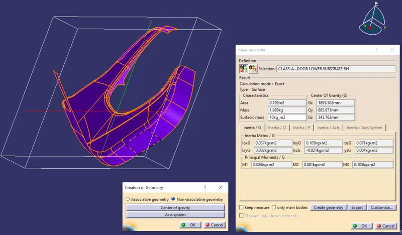
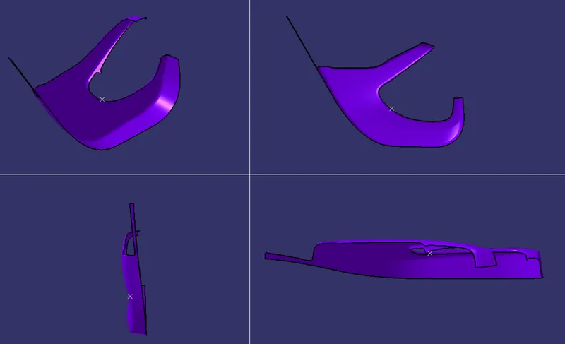
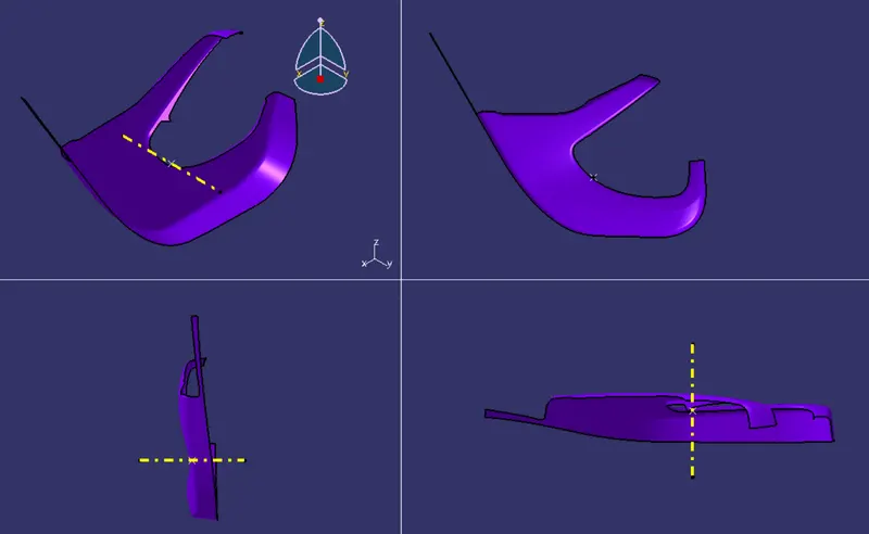
Tooling Axis created along Y axis using the CG point.
Draft Analysis on Class A surface
Few steps need to be followed to perform draft analysis.
Step 1:
- View --> Customise view parameters --> Mesh --> Material --> Ok.
- The go to Insert --> Analysis --> Feature Draft Analysis
- Click on compass from the direction, drag & drop compass on the tooling axis in such a way that Z axis to be along the tooling axis.
- Lock the compass using lock command from direction.
- Click on the surface to see the results.
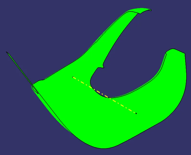
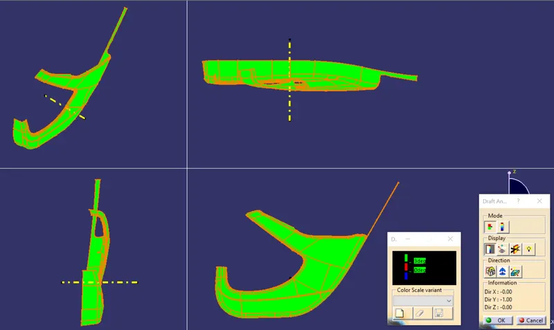
Draft Analysis on Class-A surface along Tooling Axis.
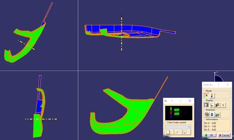
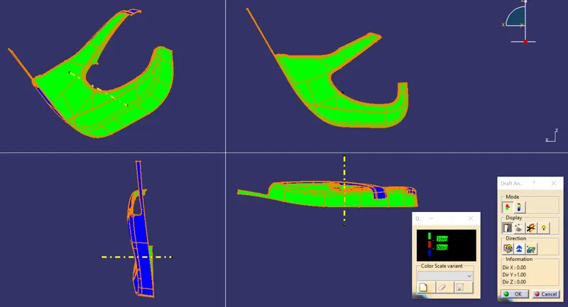
Draft Analysis on Final Trim along Tooling Axis.
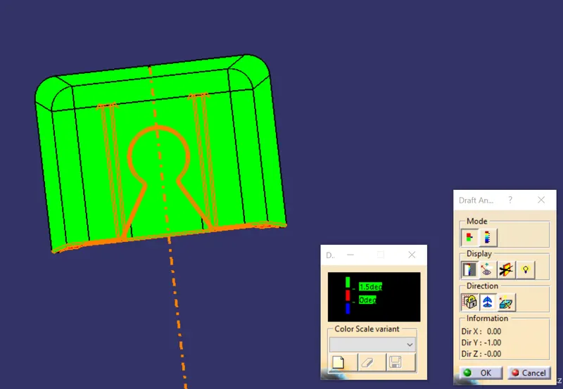
Draft Analysis on Dog House along Tooling Axis.
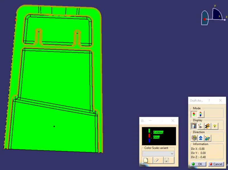
Draft Analysis on Dog House along Lifter Axis.
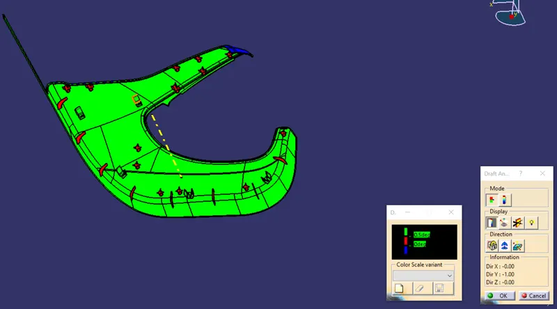
Draft Analysis on Lower Substrate along Tooling Axis.
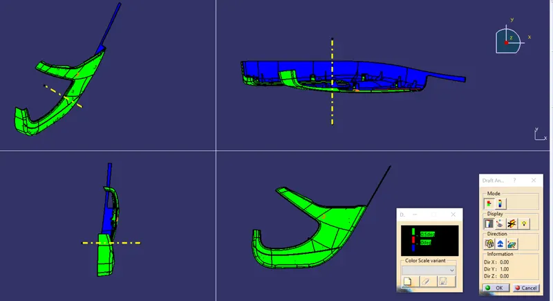
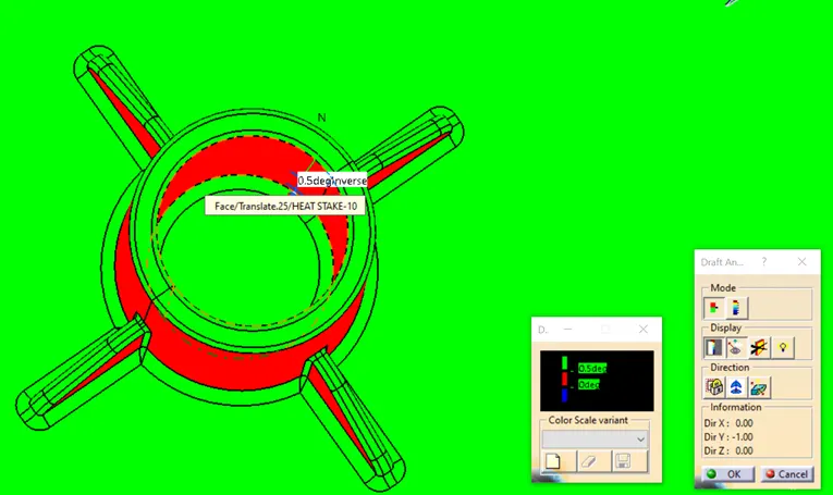
Draft Analysis on Lower Substrate surface along Lifter Axis.
Class B Surface
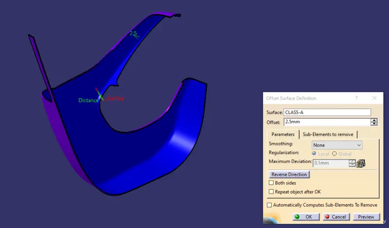
Class-B is created by off-set Class-A.
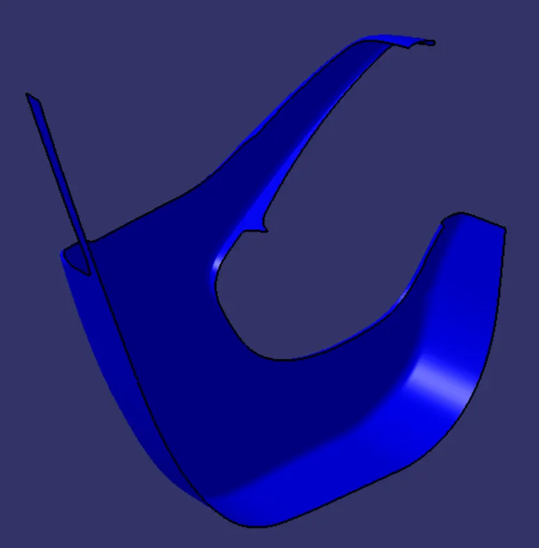
Class-B Surface
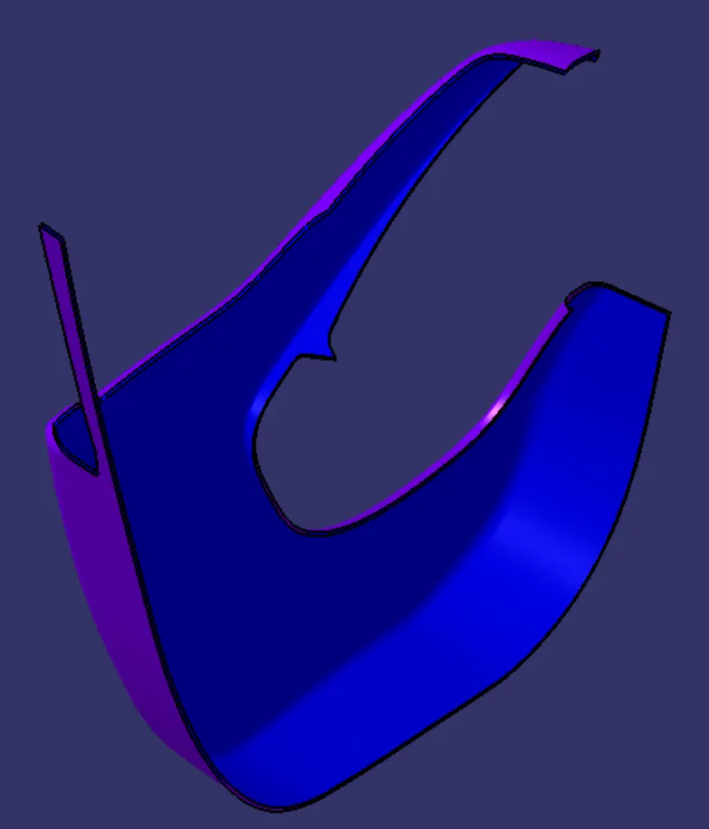
Class-A & Class-B surfaces.
Class-C Surface
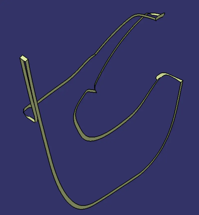
Class-C is created by drafting the edges of Class-A along Tooling Axis direction.
Class-A&C
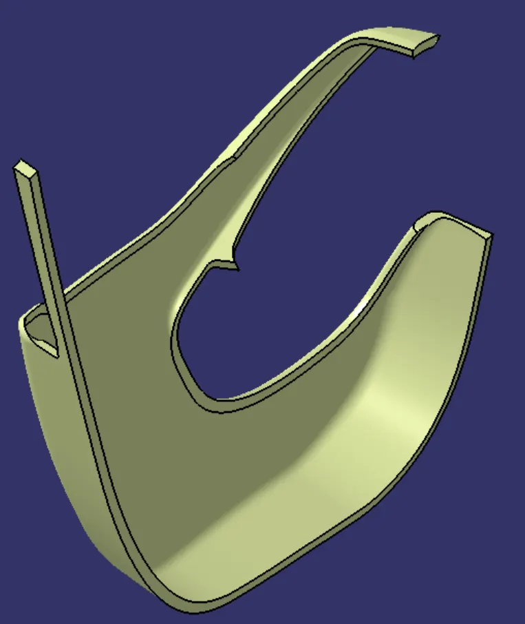
Class-A&C are joined to perform Final Trim.
Final Trim
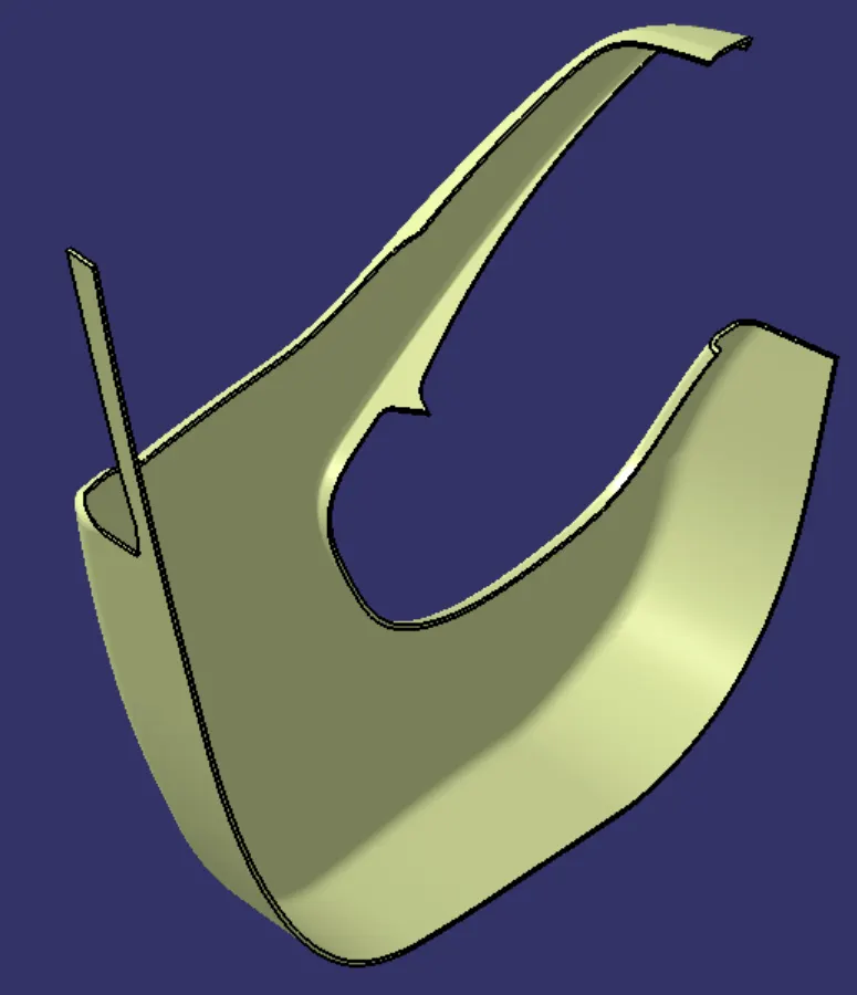
Class-B surface extrapolated & trimmed with Class-A&C, to get Final Trim.
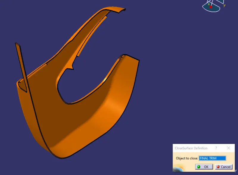
Close Body of Final Trim
B-Side Surface
Flanges were created using Master Sections.
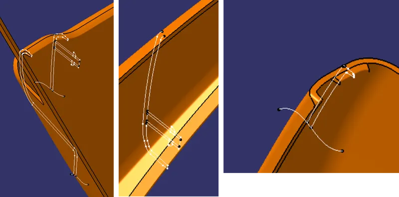
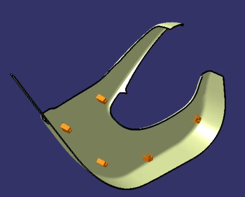
Dog Houses created to assemble the Lower Substrate with the Door Trim Panel.
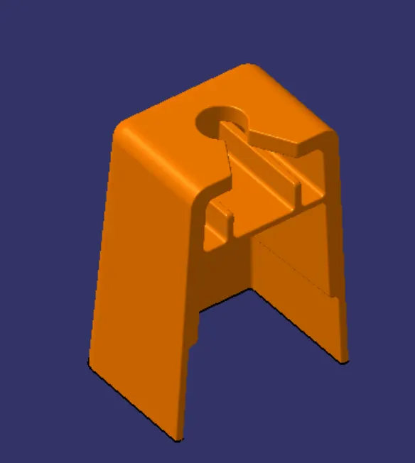
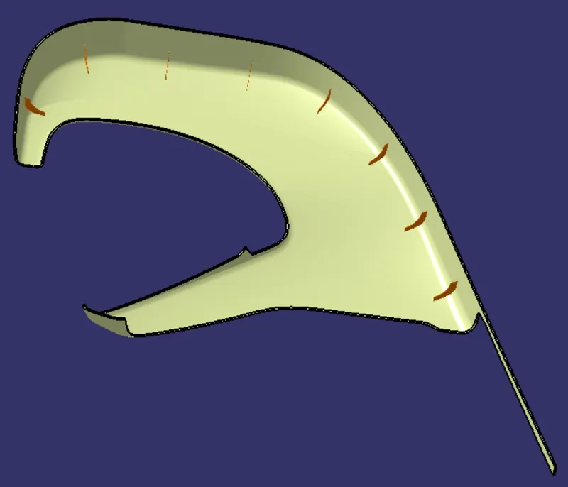
Ribs created to strengthen the part.
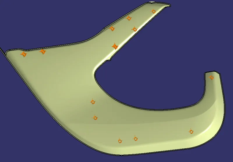
Heat Stakes created to assemble other parts with Lower Substrate.
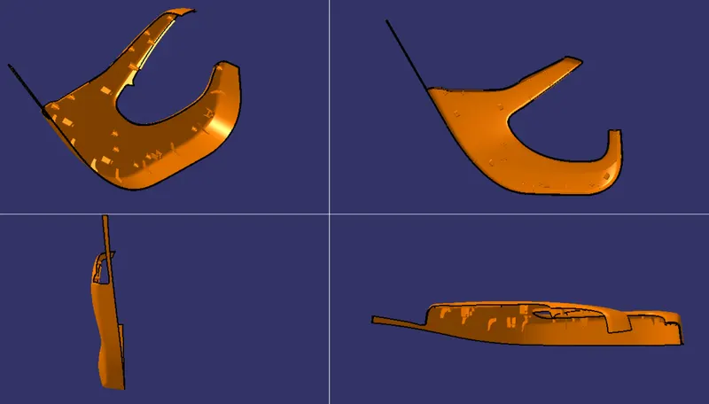
Lower Substrate with Flanges, Dog Houses, Ribs & Heat Stakes.
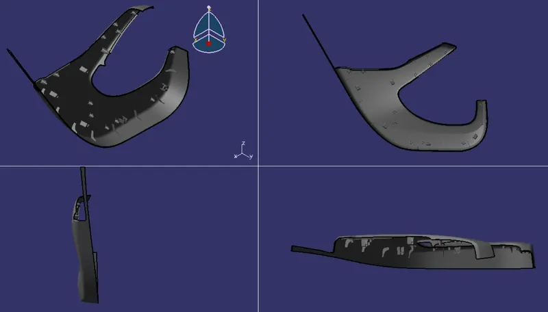
Plastic Material properties are applied to the Lower Substrate.
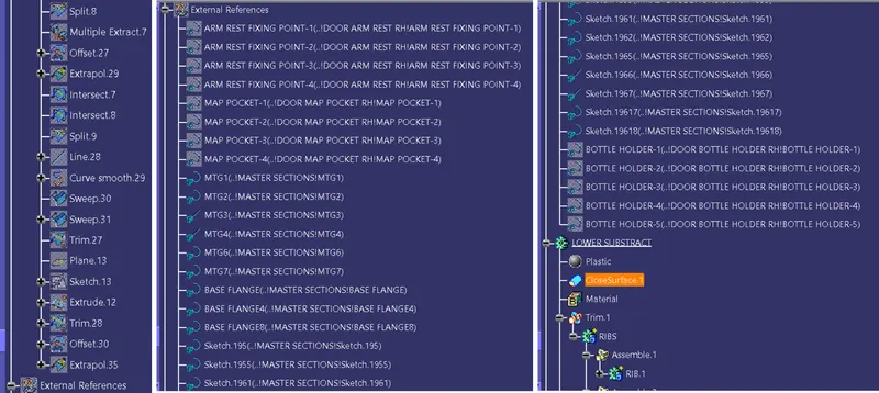
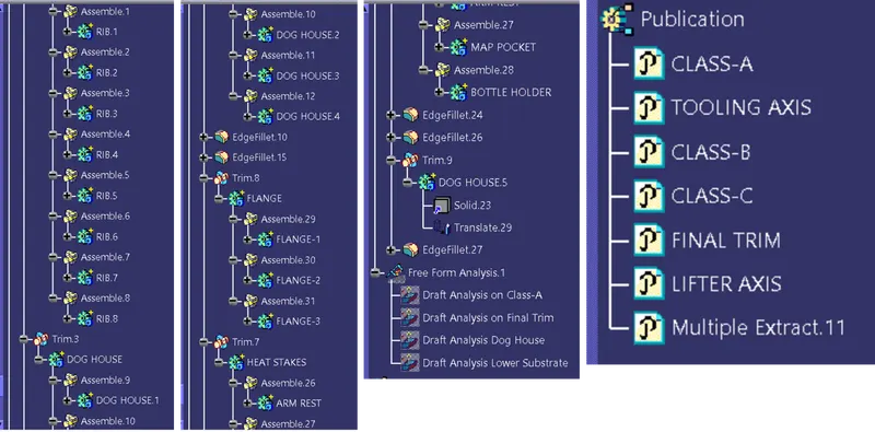
Lower Substrate Product Tree
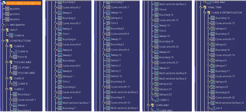
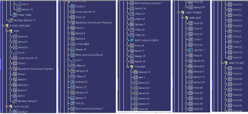
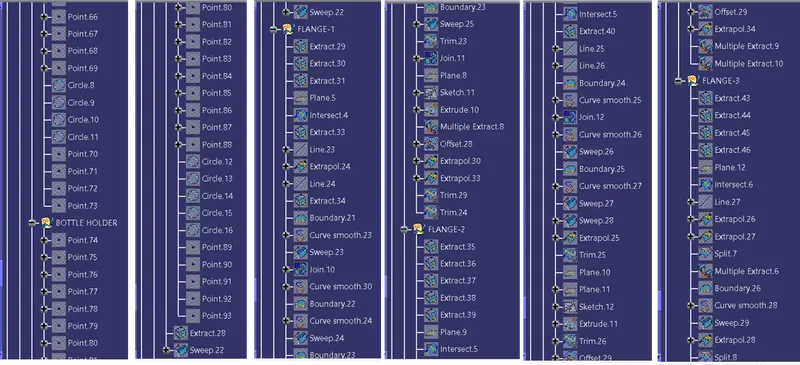
Assembly
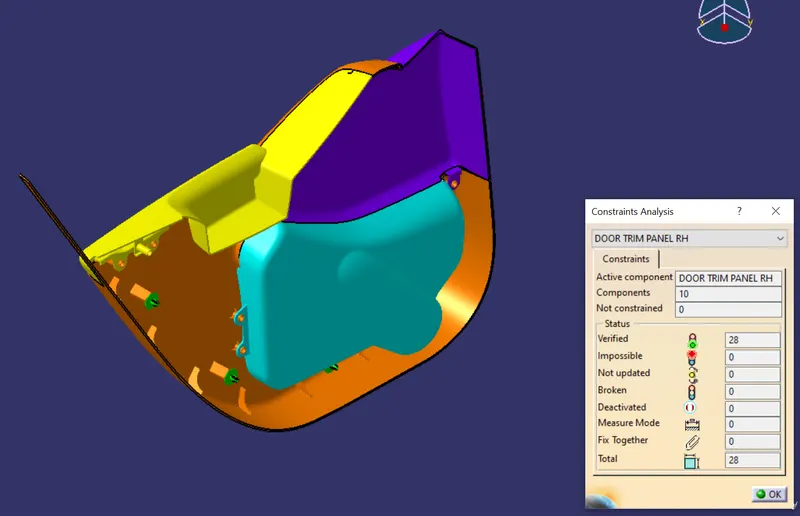
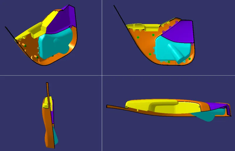
All parts are assembled properly & DoF of all parts is zero.
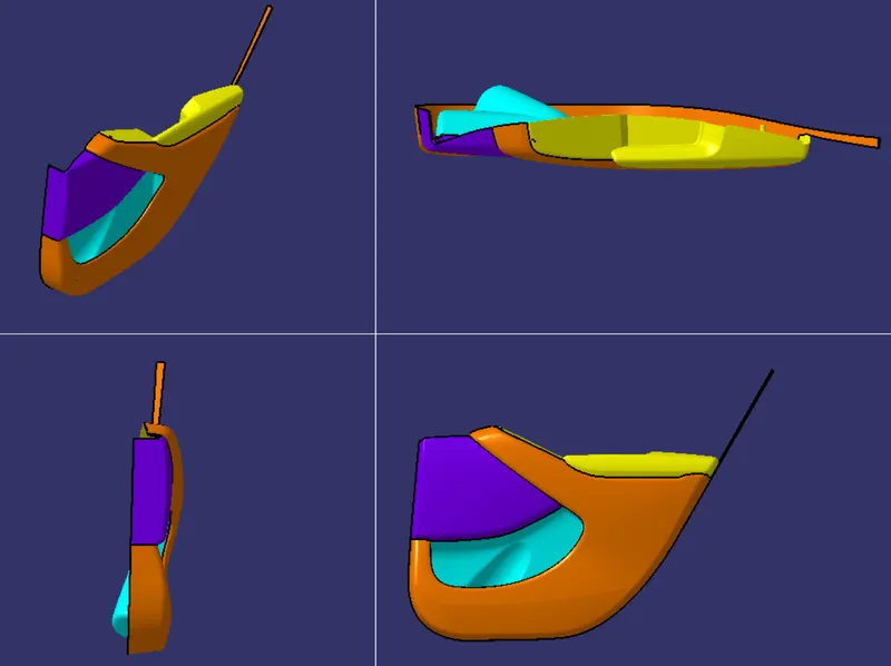
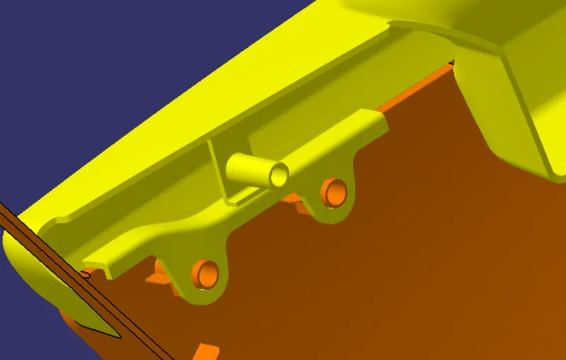
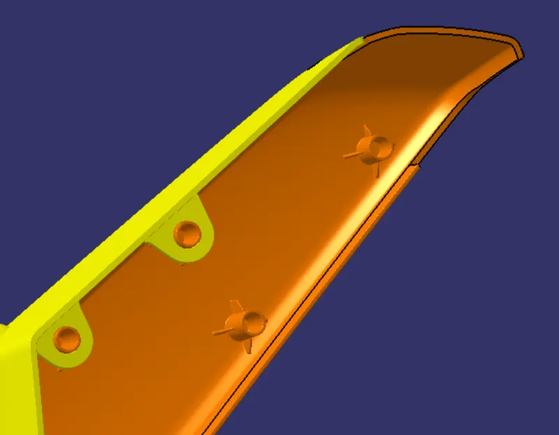
Arm Rest Fixing Arrangement.
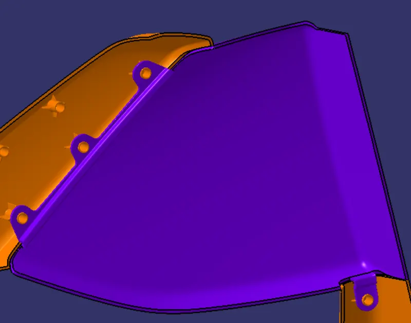
Map Pocket Fixing Arrangement.
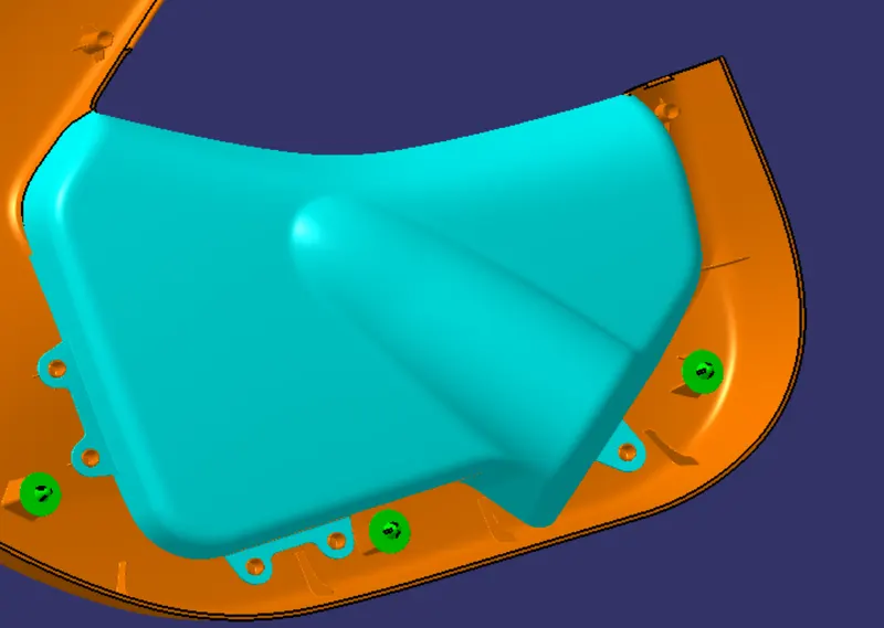
Bottle Holder Fixing Arrangement.
Flange Intereference
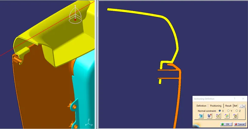
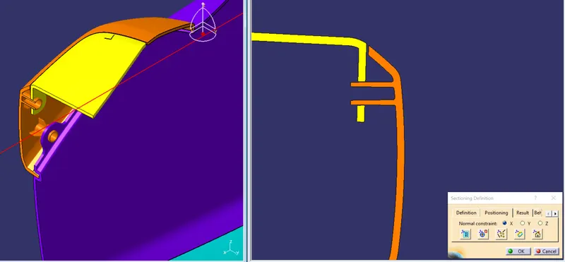
Lower Substrate & Arm rest
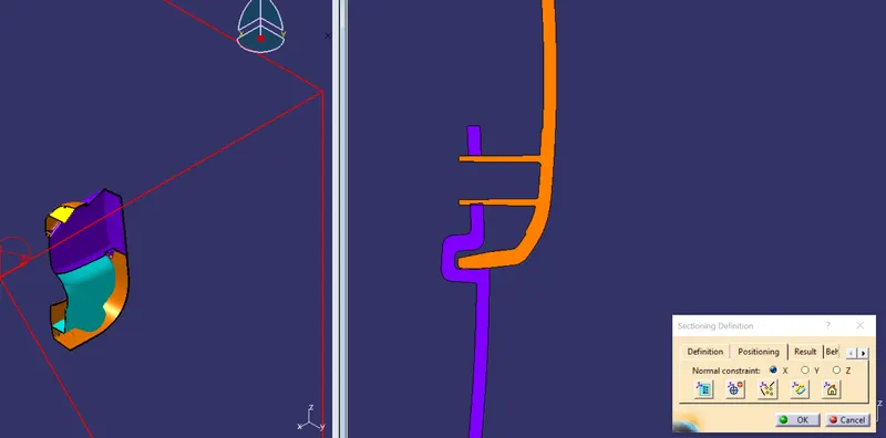
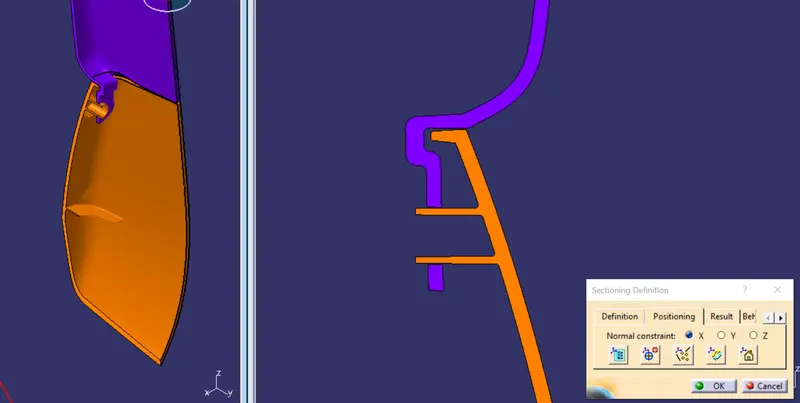
Lower Substrate & Map Pocket
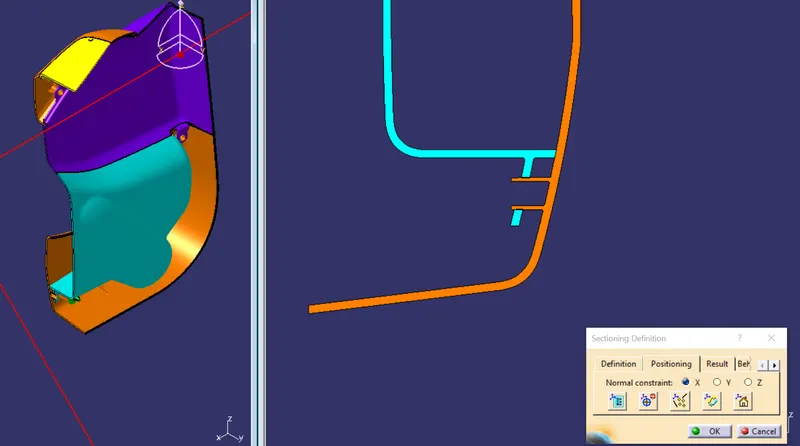
Lower Substrate & Map Pocket