Week 11 - Final project
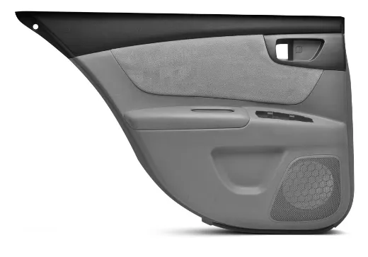
Development of a Door Trim panel
AIM
To create a door interior part from the inputs of class A surface along with master section by following the design rules followed in tier 1 and OEM industries in catia v5
SOFTWARE USED
CATIA V5
OBJECTIVES
- Create a sketch by using Positioned sketch
- All the should be sketches should be Iso-Constrained
- Ensured Proper Tree Structure
- Geometrical sets should having a proper name based on the sketches present inside of it
- Create thickened part using master section for reference
- Create the mounting features as per design guidelines in the industry and with master sections
- Creating of Draft analysis & Tooling analysis
- Creation of parting lines and check tooling feasibility.
PROCEDURE:
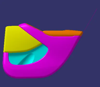
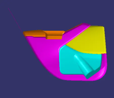
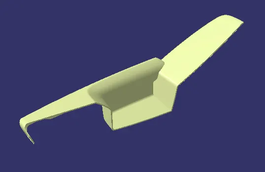
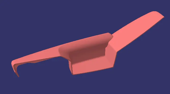
Class A surface of a door panel received from the styling team. In the automotive industry dedicated team is allocated to develop class A surface using sketches followed by ideation. Class A surface is the first input given to the plastic designer.
CLASS A SURFACE OF A DOOR PANEL GIVEN:
Front & Back Side:
DRAFT ANLAYSIS ON CLASS A SURFACE
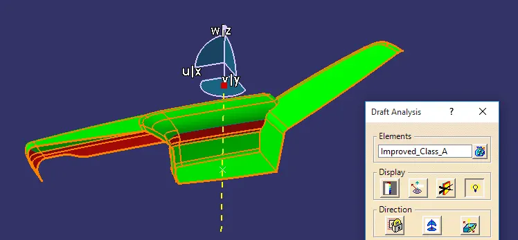
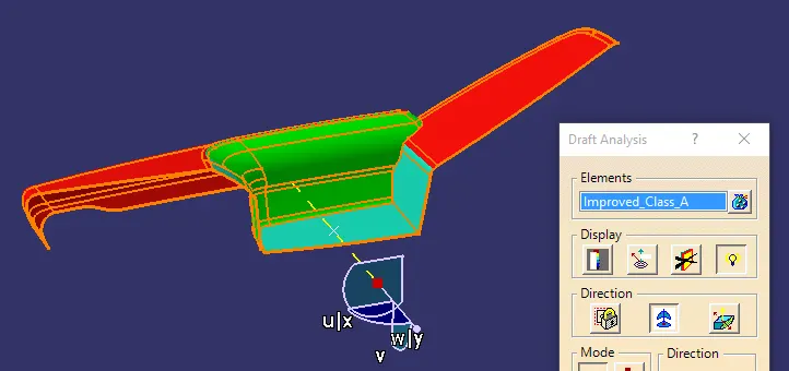
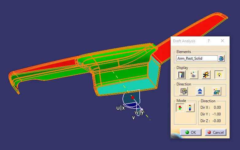
Draft analysis in catia is a command that is used to detect if the part you drafted will be easily removed from the mold. It is performed based on color ranges identifying zones on the analyzed element.
Most of the industries is using minimum draft angle is 3 degree
1. Door Arm Rest
• Creation of tooling axis
The line has been created using the line command. The point-direction option is used to create the main tooling axis in the y-direction.
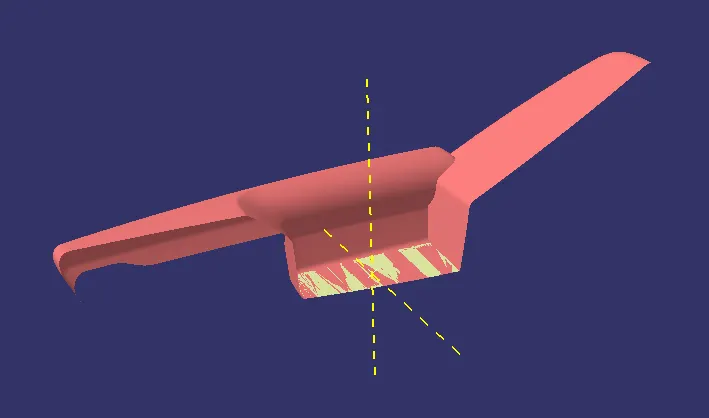
DRAFT ANALYSIS ON IMPROVED CLASS A
CLASS B SURFACE
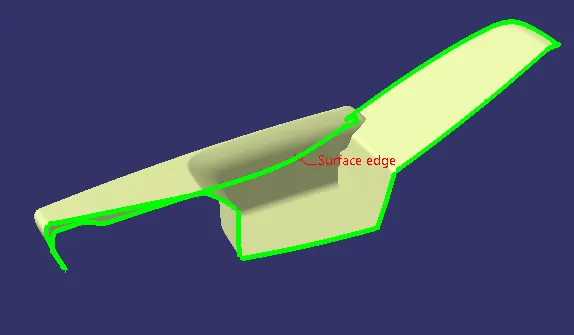
Class B surface has been created by offsetting of class A surface. Offsetting has been done using the offset command. Class A surface is offset with a 2.5 mm distance. Surfaces that were not offsetting were formed using Spline and Fill command.
CLASS C SURFACE
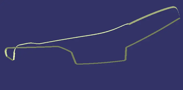
Using the Multiple extract commands, boundaries of class A surface were extracted. Class C surface joins class A and class B surfaces. It is created using the sweep command. Inputs for the sweep command were extracted boundary, class-A surface, angle value, and length of the sweep. Due to surface irregularities, it was not possible to create a single sweep. Hence, several sweeps and multisection were created, and finally, they joined together to create a class C surface.
Creation of Close Surface
Class A and Class C surfaces were joined together. The join of Class A and Class C surface is trimmed with class B surface to create a closed surface. While performing trim operation errors were coming as a proper intersection was not happening. Hence with the help of extrapolating command class B surface was extrapolated and finally trimed.
Perform Draft Analysis on Final Enclosed Surface:
- Change View Mode Customization to Material mode.
- Go to INSERT---> ANALYSIS---> FEATURE DRAFT ANALYSIS and move the compass to the Main Tooling Axis.
- Change the range to 3°.
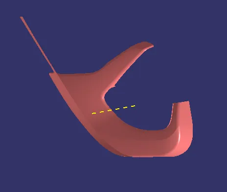
2. LOWER SUBSTRACT
• Creation of tooling axis, draft analysis.
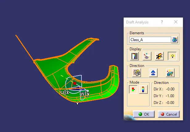
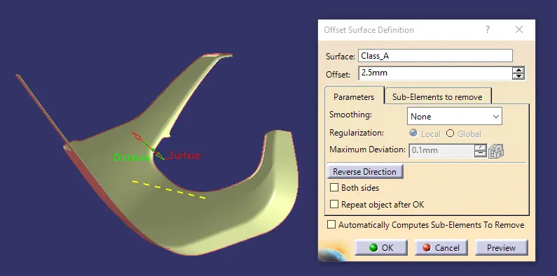
CLASS B SURFACE
Class B surface has been created by offsetting of class A surface. Offsetting has been done using the offset command. Class A surface is offset with a 2.5 mm distance.
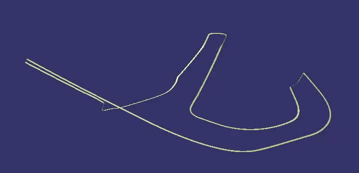
CLASS C SURFACE
Using the Multiple extract commands, boundaries of class A surface were extracted. Class C surface joins class A and class B surfaces. It is created using the sweep command. Inputs for the sweep command were extracted boundary, class-A surface, angle value, and length of the sweep.
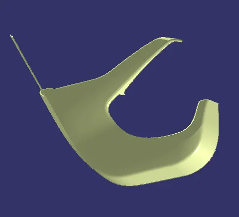
Creation of Close Surface
Class A and Class C surfaces were joined together. The join of Class A and Class C surface is trimmed with class B surface to create a closed surface. While performing trim operation errors were coming as a proper intersection was not happening. Hence with the help of extrapolating command class B surface was extrapolated and finally trimed.
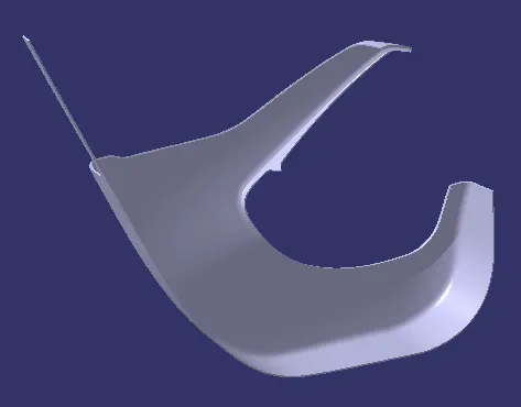
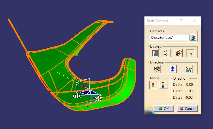
Perform Draft Analysis on Final Enclosed Surface:
- Change View Mode Customization to Material mode.
- Go to INSERT---> ANALYSIS---> FEATURE DRAFT ANALYSIS and move the compass to the Main Tooling Axis.
- Change the range to 3°.
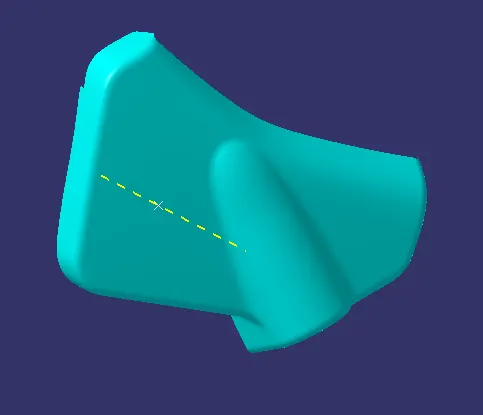
3. BOTTLE HOLDER
• Creation of tooling axis
The line has been created using the line command. The point-direction option is used to create the main tooling axis in the y-direction.
CLASS B SURFACE
Class B surface has been created by offsetting of class A surface. Offsetting has been done using the offset command. Class A surface is offset with a 2.5 mm distance.
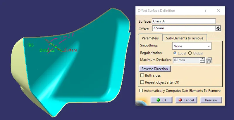
CLASS C SURFACE
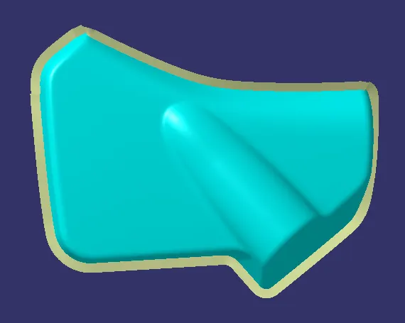
Using the Multiple extract commands, boundaries of class A surface were extracted. Class C surface joins class A and class B surfaces. It is created using the sweep command. Inputs for the sweep command were extracted boundary, class-A surface, angle value, and length of the sweep.
Creation of Close Surface
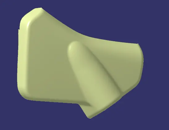
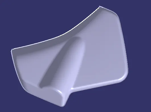
Class A and Class C surfaces were joined together. The join of Class A and Class C surface is trimmed with class B surface to create a closed surface. While performing trim operation errors were coming as a proper intersection was not happening. Hence with the help of extrapolating command class B surface was extrapolated and finally trimed.
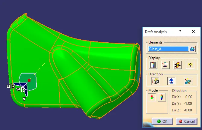
Perform Draft Analysis on Final Enclosed Surface:
- Change View Mode Customization to Material mode.
- Go to INSERT---> ANALYSIS---> FEATURE DRAFT ANALYSIS and move the compass to the Main Tooling Axis.
- Change the range to 3°.
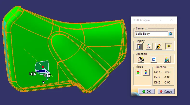
4. MAP POCKET
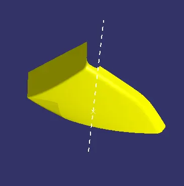
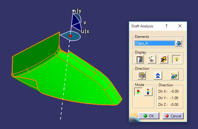
• Creation of tooling axis
The line has been created using the line command. The point-direction option is used to create the main tooling axis in the y-direction.
CLASS B SURFACE
Class B surface has been created by offsetting of class A surface. Offsetting has been done using the offset command. Class A surface is offset with a 2.5 mm distance.
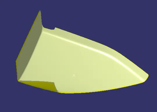
CLASS C SURFACE
Using the Multiple extract commands, boundaries of class A surface were extracted. Class C surface joins class A and class B surfaces. It is created using the sweep command. Inputs for the sweep command were extracted boundary, class-A surface, angle value, and length of the sweep.
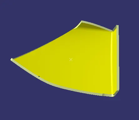
Creation of Close Surface
Class A and Class C surfaces were joined together. The join of Class A and Class C surface is trimmed with class B surface to create a closed surface. While performing trim operation errors were coming as a proper intersection was not happening. Hence with the help of extrapolating command class B surface was extrapolated and finally trimed. Create the solid part.
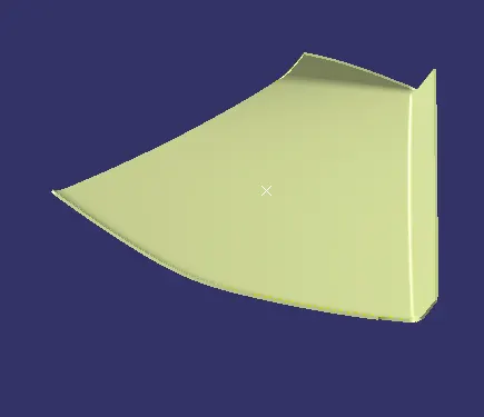
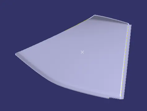
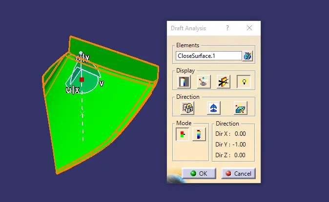
Perform Draft Analysis on Final Enclosed Surface:
- Change View Mode Customization to Material mode.
- Go to INSERT---> ANALYSIS---> FEATURE DRAFT ANALYSIS and move the compass to the Main Tooling Axis.
- Change the range to 3°.
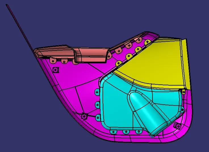
CREATION OF AN ASSEMBLY:
- Door Arm Rest
- Lower Substr
- Map Pocket
- Bottle Holder
Creating B-Side Engineering Features
1.Ribs
2.Screw boss
3.Heat stakes
4.Locators
5.Dog House
6.Push pin
Heat Stakes and Ribs:
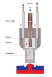
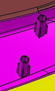
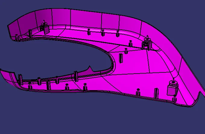
The use of heat stakes is to attach two plastic components permanently. A total of 13 heat stakes were placed at different locations on the lower substrate. One heat has been created onto the door armrest part which will be attached to the upper substrate. Following the muster section, the outer diameter of the heat stake is 7.5 mm and the inner diameter is 4.5 mm. Necessary slots are made onto other parts where heat stakes will attach together. Draft of 0.5 degrees has been given to all the heat stakes. All the heat stakes have ribs attached to them. All the ribs have 1mm thickness and 0.5 degrees of the draft. The length of the ribs is 10 x 10 mm.
Heat staking also known as thermoplastic staking is the process of joining two dissimilar materials together. In heat staking, we use local heating and cooling to raise the temperature of plastic components and allow plastic reforming to be carried out. This reforming can be used in a wide variety of applications
LOCATOR
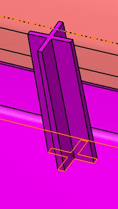
Extract the surface that we going to create locator. Use positiioned sketch and draw a locator sketch. Use pad commands for the sketch to till we required. Draft the locator for minimum of 0.5 degree. Assemble the locator to lower subtrate solid.
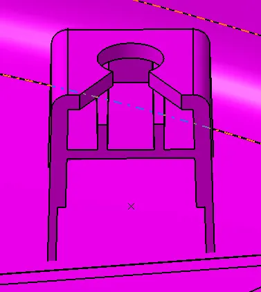
DOG HOUSE:
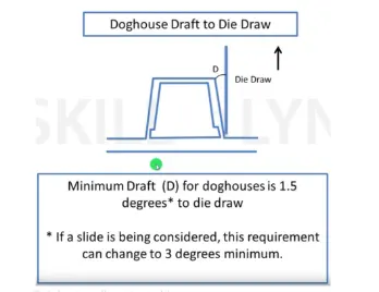
Dog house is an engineering feature used in the plastic trim design. Doghouses are used as supporting features. Sometimes other engineering features like snaps; locators, etc. are mounded on them to increase their strength. Dog houses are subjected to draft analysis to prevent breakage of the component during ejection from the mold cavity. Dog house and other engineering components are built on B-surface.
PUSH PIN
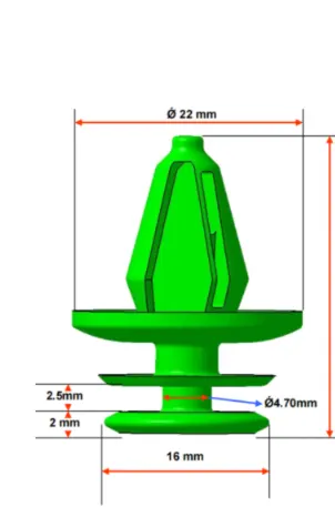
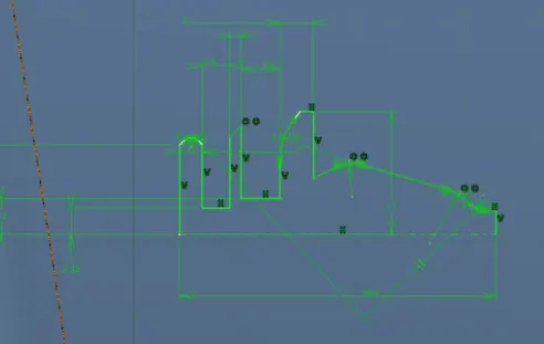
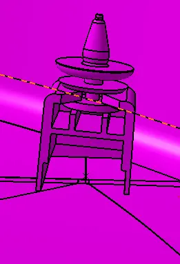
Push pins-Push pins are used for joining one component to another. These are basically attached to the dog houte For creating the push pins I have taken the following reference basically the measurements.
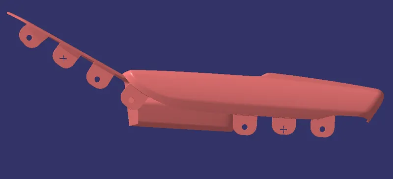
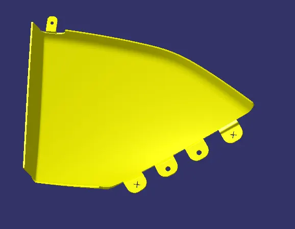
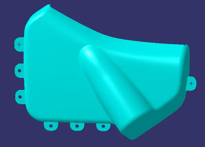
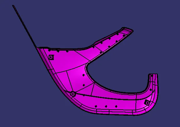
FLANGES
1. ARM REST
2.MAP POCKET
3. BOTTLE HOLDER
4. LOWER SUBSTRACT
FULL ASSEMBLY
CONCLUSION :
Class-B and Class-C Surfaces are created to the given Class-A surfaces. The design of B-side features is done and they are assembled successfully. A detailed report has been prepared and all the part bodies and assembly has been attached to the challenges successfully.