Week 11 - Final project
The main Aim of this project is to development of Door trim panel and adding the Engineering features to it.
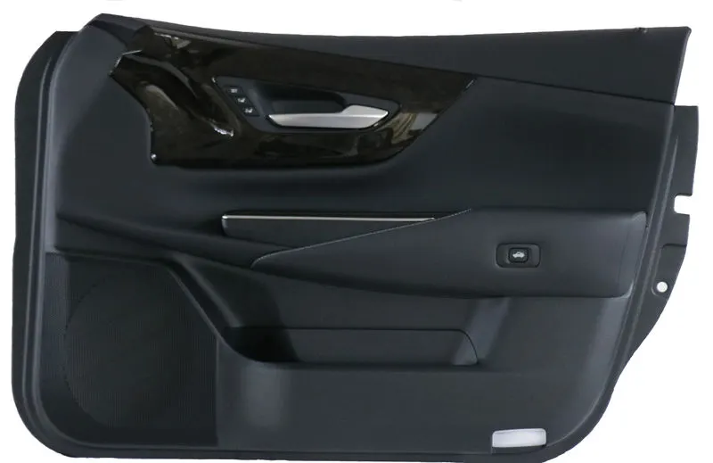
The above shown is a picture of Door Trim Panel.For creating the required Door Trim Panel,First we need to create the solidbody from the given Class A surface.Then we have to attach the Engineering features it.
At first we have to make the Solid surface.For that we have to make Class C Surface and Class B Surface from the Class A surface.
The aim is to generate the Class B and Class C surface from the given Class A Surface.So,the main overview/important steps for this operation is
- Creation of the Tooling axis
- Perform the draft analysis on given tooling axis
- Offset the Class A surface to given thickness
- Clearing the patches of offseted surface
- Performing the sweep command
- Finally making a closed body
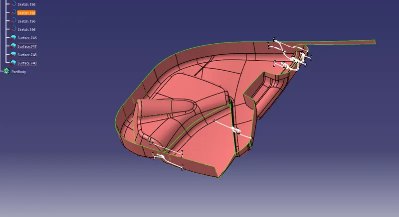
The above shown is the given surface we will obtain.There are four different surfaces.They are Lower Arm rest,Lower substrate,map pocket and Bottle holder.Since it is given the all surface together,we must isolate the each surface seperately and work on the individual surfaces.
1.ARM REST
First step is the creation of the Tooling axis
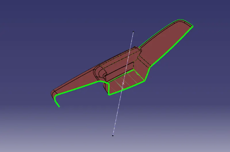
For making the Tooling axis,first we have to find a flat surface and create a point on it.Then create a line withrespect to that point.Thus,the Tooling axis will be formed.
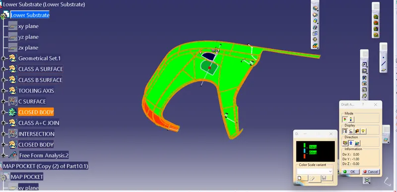
The next we have to check whether the Tooling axis will clear the draft or not.For that we have to perform the Draft Analysis
- Go to Insert -> Analysis -> Featured Draft Analysis
- Place the Compass into the Tooling axis
- Change the value of degree into 3
- After inserting the a compass,click anywhere on the surface
- If the green colour occurs,it means that draft is cleared successfully(We can check the angle by enabling the "Analysis under running point"
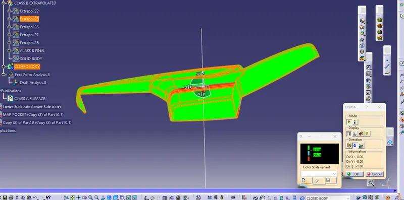
In this area,there are some areas that are not clearing.So,there is some irregularity in the Class A Surface itself.But it can be cleared by the sidecore axis.
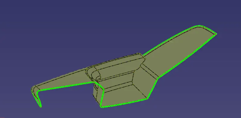
The next step is to creation of the B surface.The mentioned thickness given here is 2.5mm.So,we have to offset 2.5mmAfter offsetting,some patches will appears.We need to rework on the patches and make the surfaces good as shown below.
The next step is the creation of the C surface.
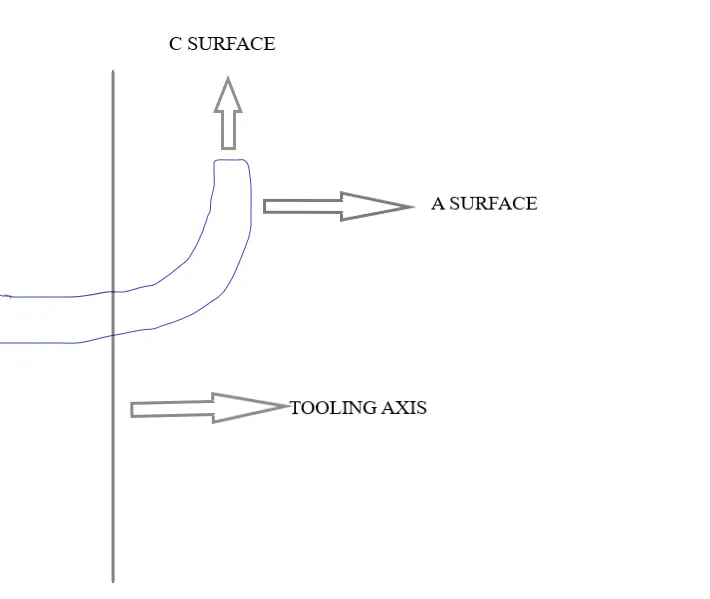
When C Surface is perpendicular to the Tooling axis,we should use sweep with the refernce surface with the angle 90 degree as shown in the above figure.
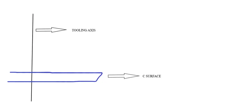
When the C Surface is parallel to the tooling axis,we will approach sweep with draft direction with the angle 3 degree.
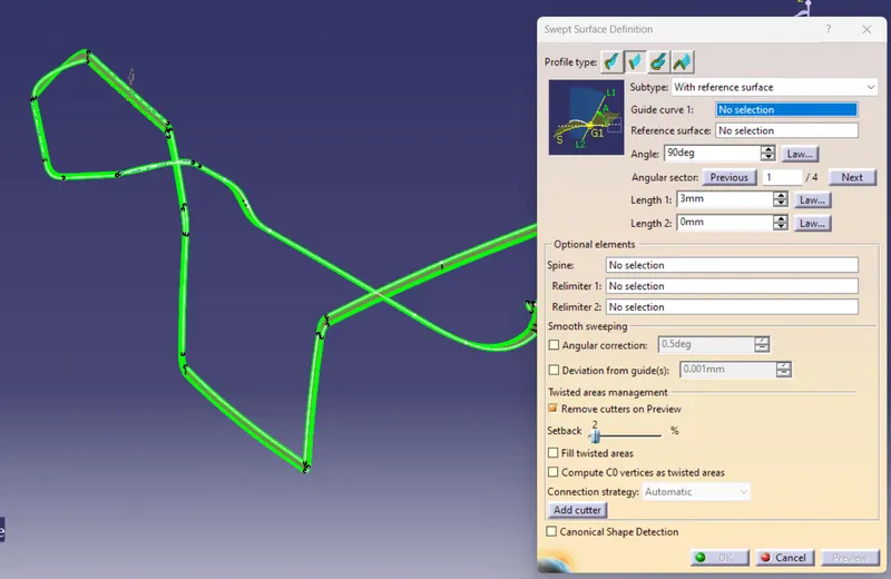
While we doing the sweep with the refernce surface,at first we should select the secand profile type.Select the option "with the refernce surface" from the subtype of the "With the reference surface".Select the guide curve by tking the boundary and select the refernce surface as the closed body.
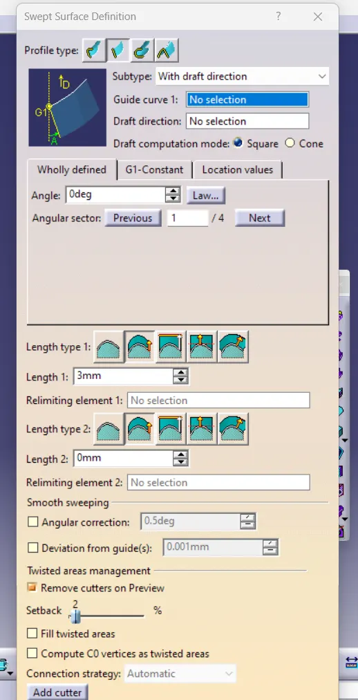
In the case if we want to do the draft direction,we want to select the draft direction from the subtype,and select the guide curve and the tooling axis.
Trim the surfaces after sweep after extrapolating and join all the C surfaces together
Then join with A and C
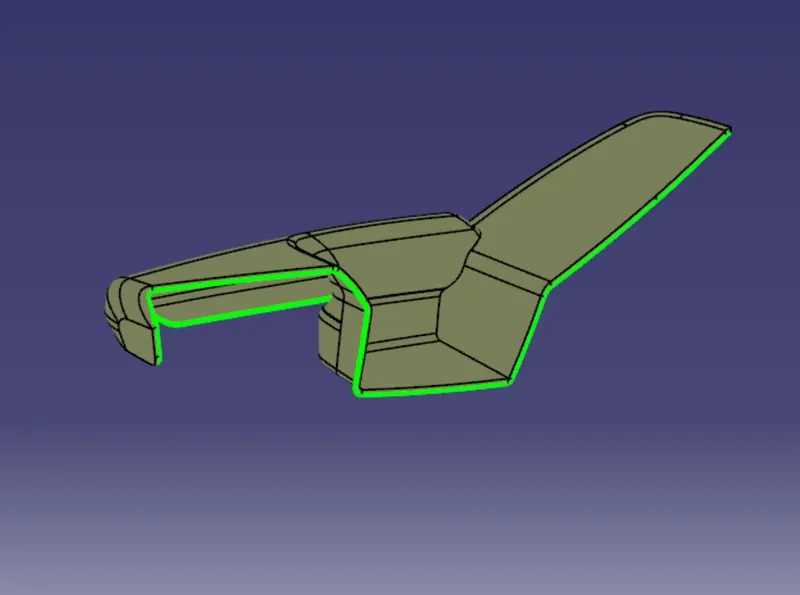
Next step is to join A+C Surface with the B surface.Before that we have to extrapolate the B surface.There might be some issues while extrapolating the B surface.An error will show forming the cusp.So,it is recommended to divide to multiple boundaries and extrapolate seperately.
The next step is to trim B surface with the A+C Surface.For that we have to check for intersections.If the intersection is not perfectly happened,extrapolate it furthur that particular surface
Then we will get the trimmed surface
Put it in part body and make it in closed surface
2.LOWER SUBSTRATE
Class A Surface
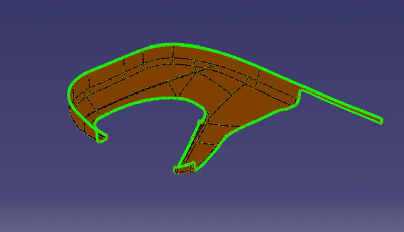
Tooling axis creation
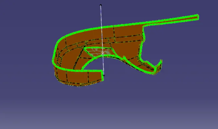
Draft Analysis
B Surface
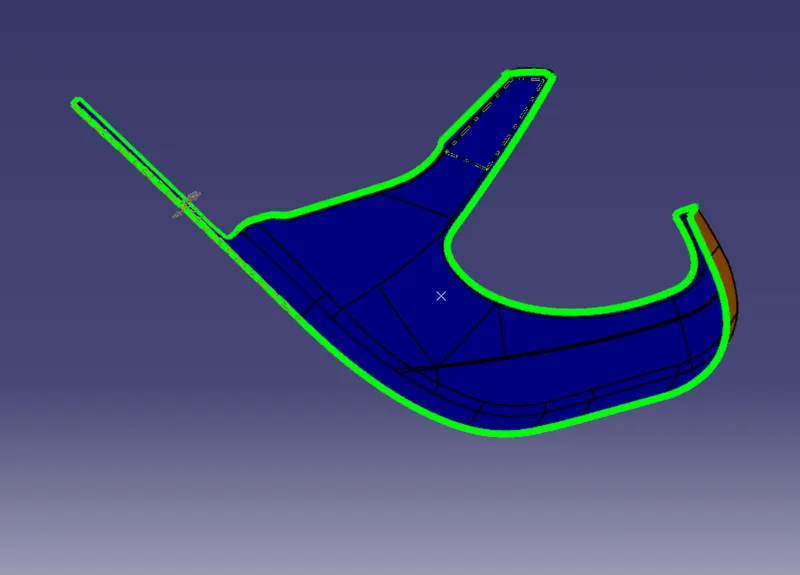
C Surface
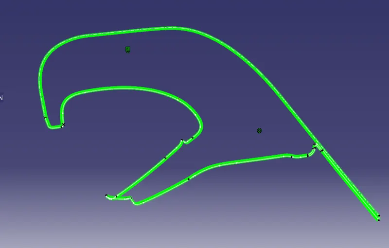
A+C Surface
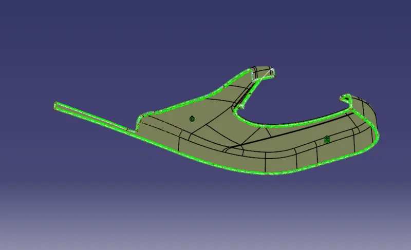
Solid Surface
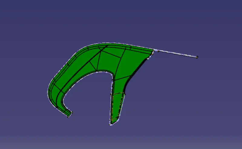
3.MAP POCKET
Class A Surface
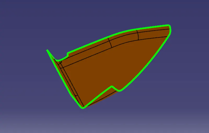
Tooling axis
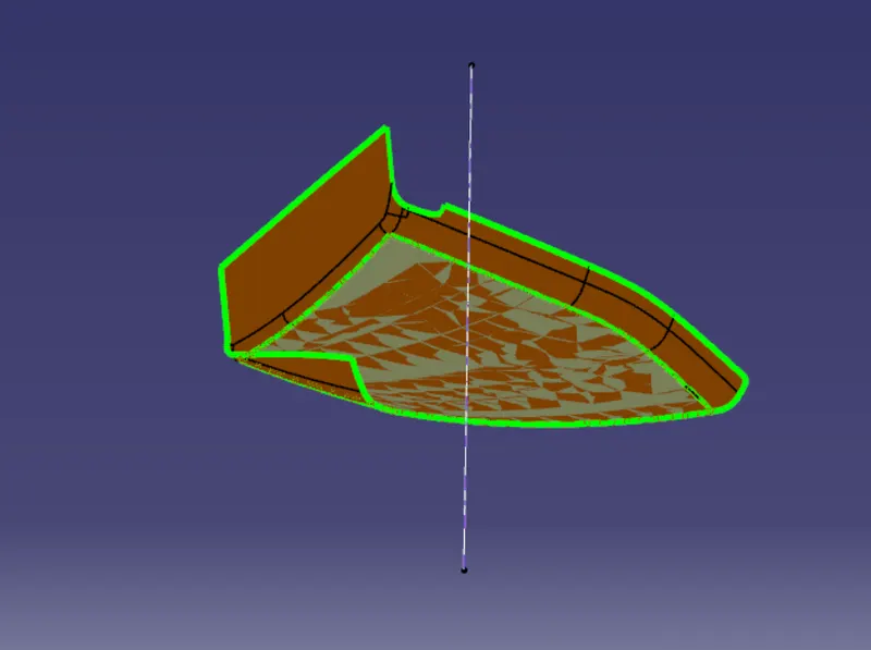
Draft Analysis
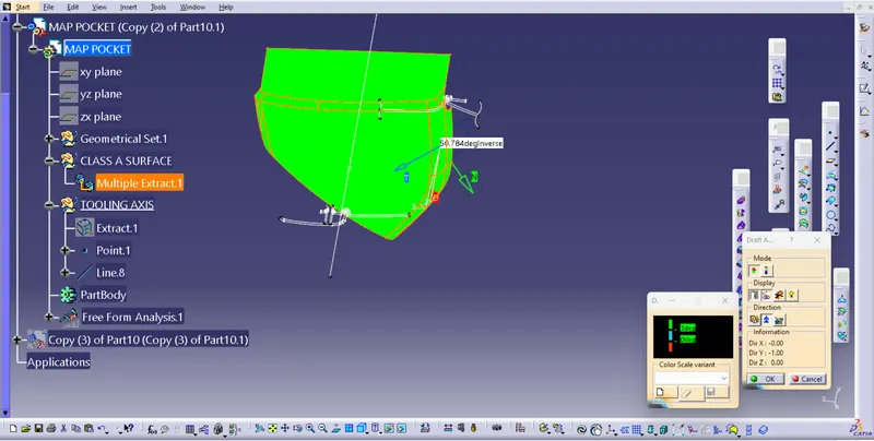
Class B Surface
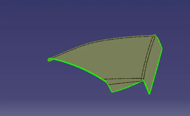
Class C Surface
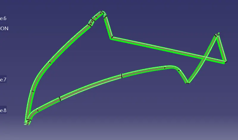
Class A+C Surface
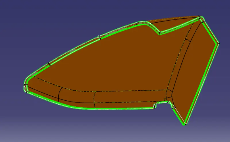
Closed Body
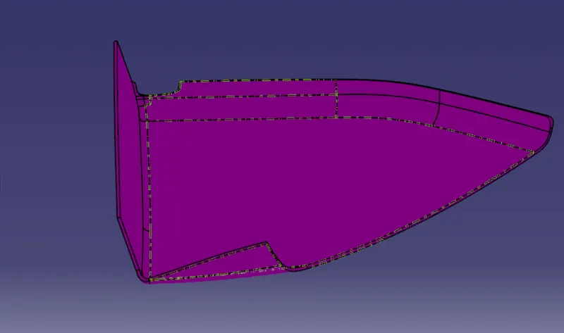
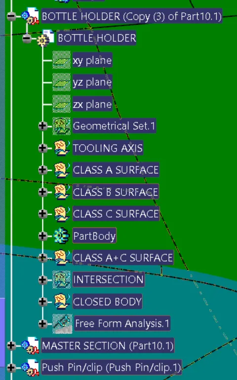
4.BOTTLE HOLDER
Class A Surface
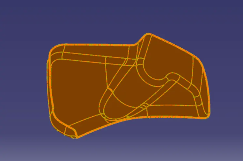
Tooling axis
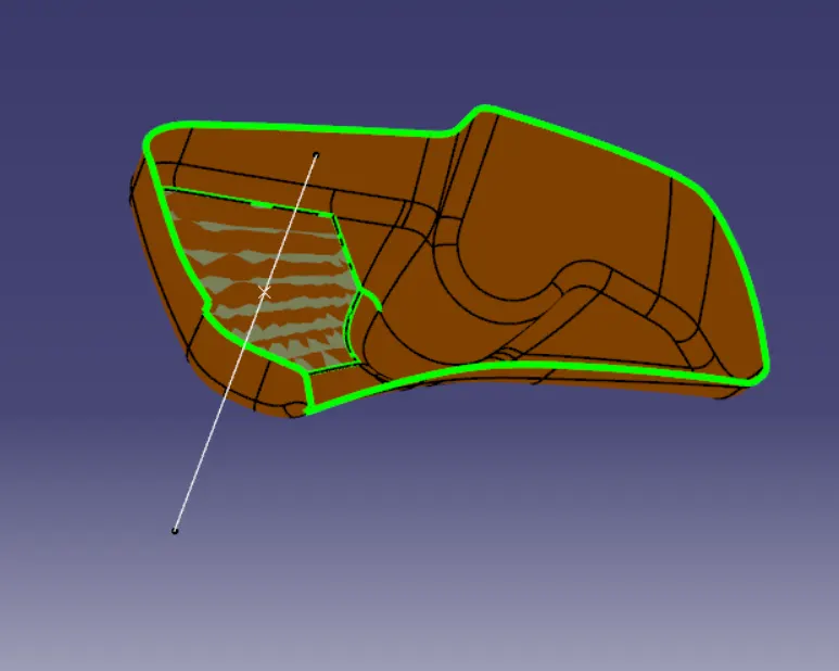
Draft Analysis
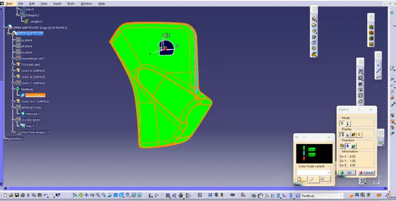
Class B Surface
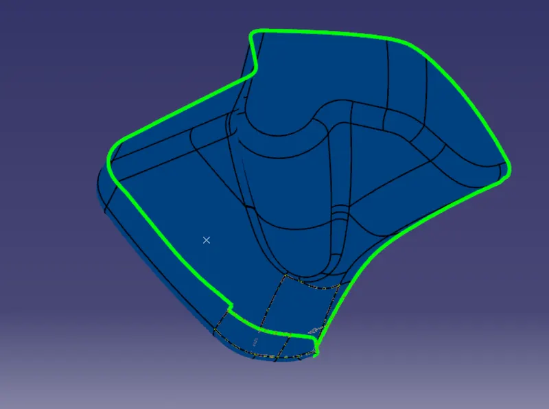
Class C Surface
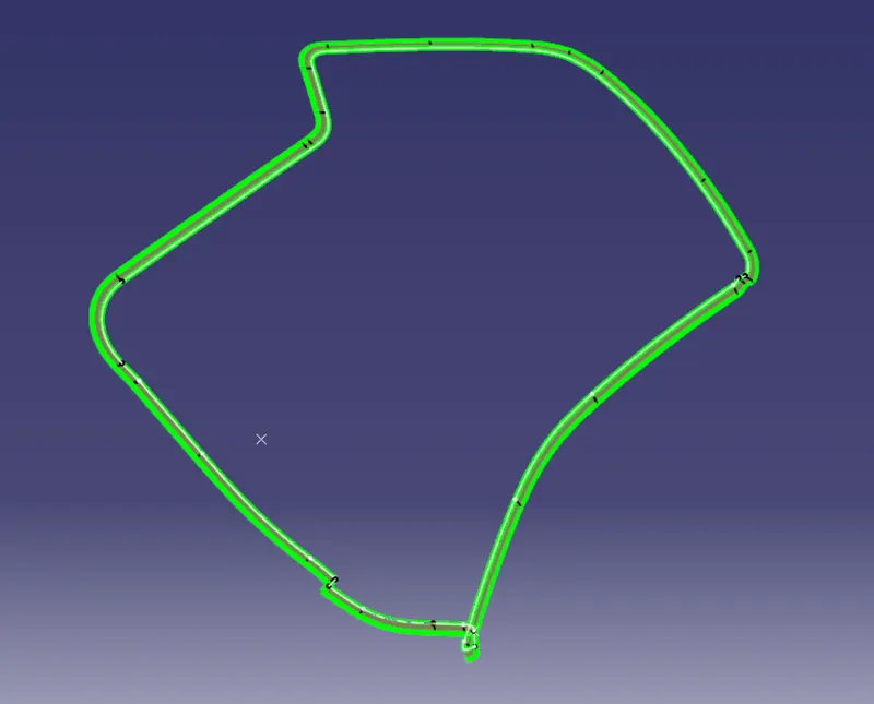
Class A+C Surface
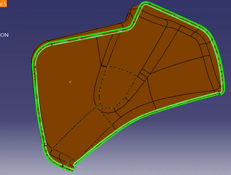
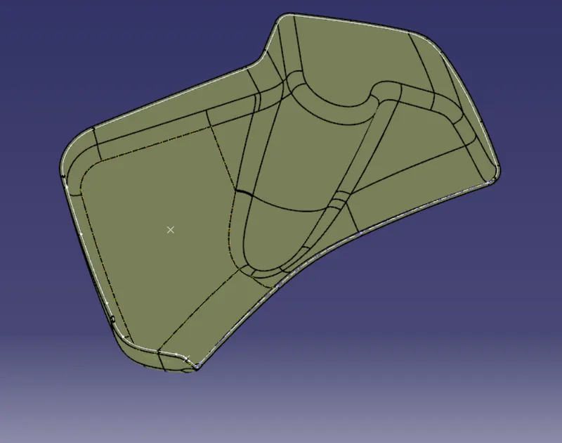
Closed body
CONCEPT OF CORE AND CAVITY
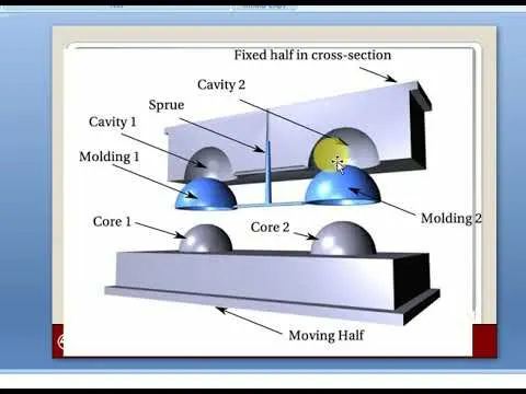
As shown in the figure core is the moving part and cavity is the fixed part.As the core is the moving part,ejector pin will be in the core.The cavity will come in the Class A Surface and and core will come in the Class B Surface.The Class A Surface is actually visible to customer.So,it should have Aesthetic appearence.The engineering features and Ejector pinmarks will comes in the B side (Core block) which are not visible by the customers.
Parting line and Parting surface :
A parting line, in the industrial casting of molds, is the borderline in which draft angles change direction. That is, it is the dividing line that splits the core and cavity halves of a molded part. It is sometimes a starting point for the mold parting surface.
The intersecting the parting surface, core, and cavity across the ZX plane gives the intersecting line that tells the parting line.
Parting surface:
The parting surface of a mould are those surfaces of both mould plates adjacent to the impressions which butt together to form a seal and prevent the loss of plastic material from the impression.
ENGINEERING FEATURES
Master section:Master section is generally guide to draw the parts of plastic components.Through the Mastersections the dimensions will be available
DOG HOUSE
Dog house is an engineering feature used in plastic trim design. The primary function of a dog house is to avoid sink marks on the class A surface which may occur due to features such as a thick screw boss or rib on the backside of Class A.
The design guideliness for making the doghouse are:
1.Draft: minimum 0.5deg.
2.Sink saver: height (C) = 40% of nominal thickness. Width (B) = 3.0mm-6.0mm.
3.Optimal radius:0.25mm
The steps to draw the doghouse are :
The height of the dog house is taken as the 30mm and thickness is taken as the 2.5mm.The profile of the doghouse is drawn in the part workbench.First pad the sketch of 30mm width and the 30mm height.After perform the shell option.Draft with 1.45 degree for the outside.After thet draw the sidecore.For drawing the sidecore,take the height as the 4mm.Then create a sidecore axis.Draft 0.5 degree the innersides withrespect to the sidecore axis.
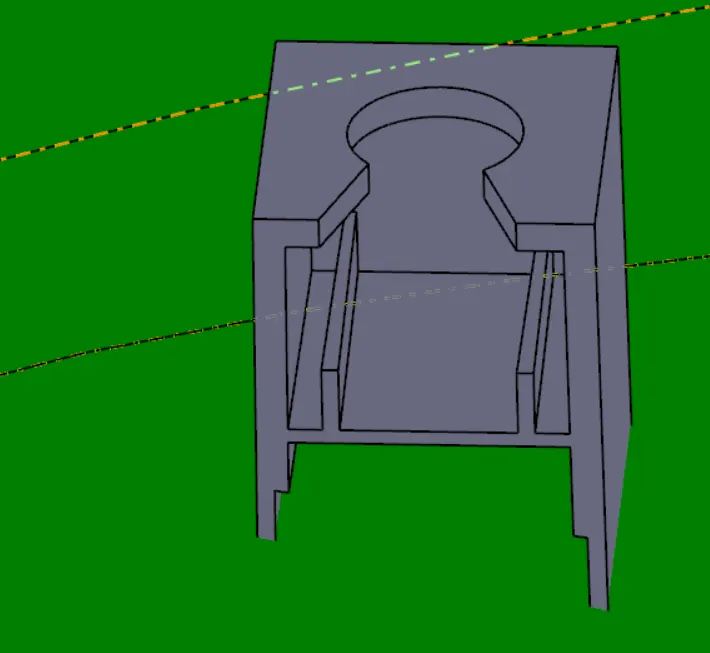
Draft analysis on doghouse:
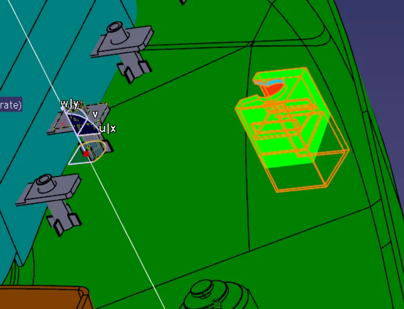
In addition to this we have to draw a rib for the support for the Pushclips that is going to enter.Also innadition to that a hole for the pushclips also to be made.
HEAT STAKES
Heat stakes are one of the permanent joint.Normally the heatstakes will have a boss and the flange will be created along with it which has a hole.
The general guidelines for designing the heatstakes:
1.Draft: minimum 0.5deg.
2.Height (C) = 25 mm. Inner Diameter = 4.5mm,Outer Diameter =7.5mm
3.Optimal radius:0.25mm
We should provide a rib to support the Heat Stakes
1.Draft: minimum 0.5deg.
2.Height = 3 to 6mm. Base Length*Width=15*15mm, Thickness=1mm
3.Optimal radius:0.25mm
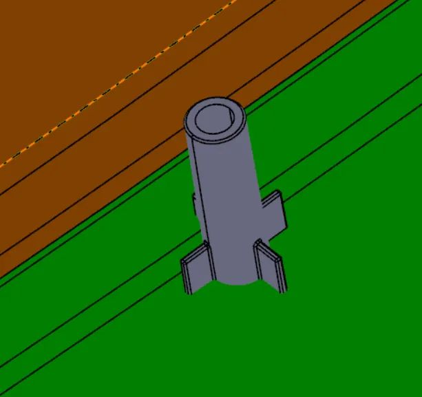
Draft analysis on heat stakes:
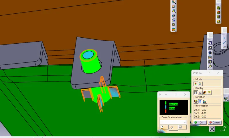
For drawing the heatstakes,first we have to create the point and make a plane with the option " Plane parallel to the point".Draw two circles with sketch of diameter 4.5mm and 7.5mm.Then extrude upto 25mm.The next step is to give the draft.Select the face that should be draft,the angle provided should be 0.5 degree and the pulling direction should be given as the draft direction and the neutral section should be provided as bottom section. Inorder to draw the rib,Create a sketch.Then draw a line 15mm perpendicular to each other.Extrude with aheight of 6mm and add a thickness of 1mm.
FLANGE
Flange is generally used for fixing the heat stakes.Wherever there is provision for the heat stakes,the flanges must be provided.The mastersection will be provided for the drawing of the flanges.We can take the dimensions of the flange directly from the mastersection.
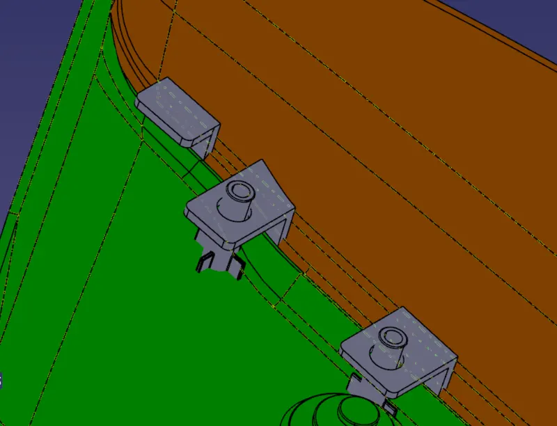
Extract the surface in which direction of the falnge to be made.For drawing the flange,we can take the refernce as the point that created the heatstakes.Create a plane in the Y axis from that point.Take a intersection between the extracted surface and the plane that is made.So,we need to take the intersection point as the base of the sketch and start the positoned sketch and create the profile of the drawing and add the thickness of 2.5mm.Fillet is provided of 2mm at the edges.
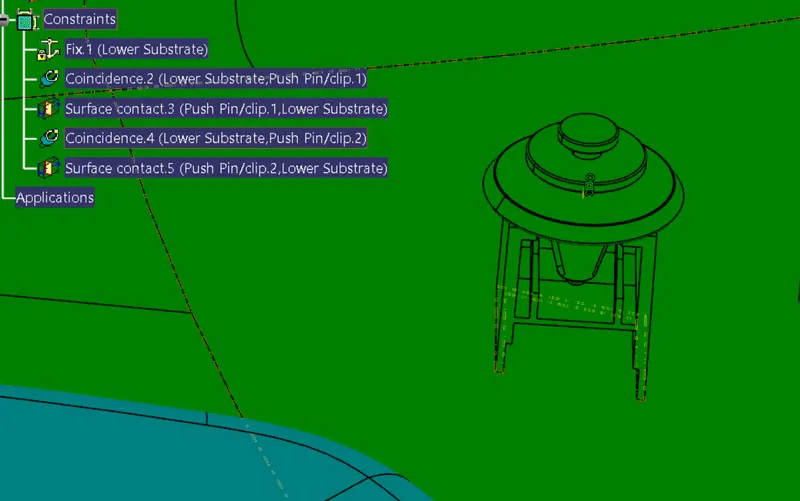
The next step is the insertion of the pushpin.The assembly file is already given and we just need to place the pushpin on the top of the doghouse.
Steps to get into product workbench:
File -> New -> Product
To import the component drawing to the Assembly/product workbench:
- Click on the existing component toolbar
- Click on the Mainpart
- Then the folder containing the folder will appears
Important guidelines to be taken care of while in Product workbench
While double click in the part as marked in above figure,it will go to the part design.To get back into the Assembly,you want to just double click the Product on the above.
Manipulation : Click on manipulation and select the direction,drag the component accordingely.
The first part to be fixed to be taken as the reference.These are the main guideliness to be followed in Assembly workbench
inorder to make axis on a part to be constrained
- Click on the part
- Take Generative shape design
- Click on Insert->Wireframe->Axis
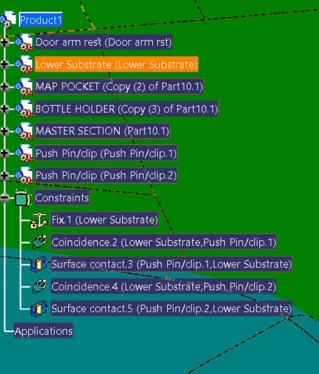
The constrains that used in this Project are:
Coincidense constrain:In coincidense constrain we have to select the centre axis of the two components and then click local update
Contact constrain:In this constrain,we have to select the phase of one part and select the phase of the secandpart and then apply local update.
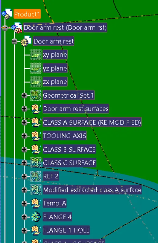
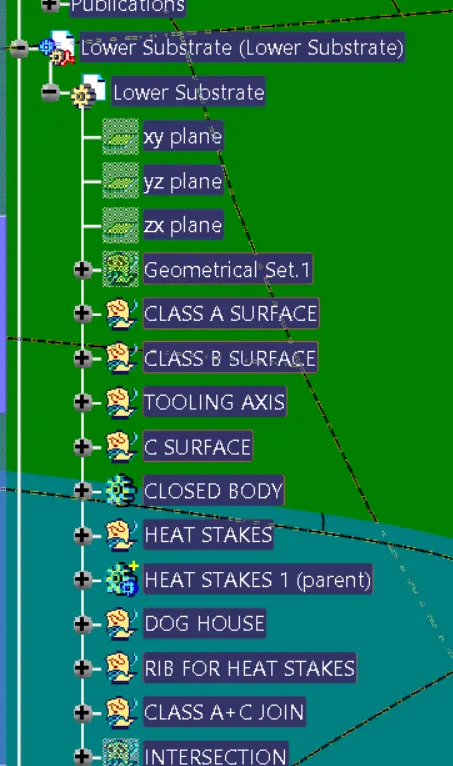
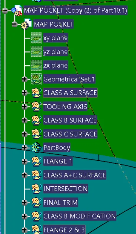
TREE STRUCTURE