Week 11 - Final project
AIM:
To develop the door trim (interior) panel with the given class A input and master sections using CATIA V5.
DOOR TRIM:
The panel covers the inside of door trim where various electrical components of the car are connected.We design the plastic side of door trim panel which is attached the sheet metal through various b side features.
The object is thickened to get the component which is suitable for manufacturing.
ROLE OF PLASTIC IN AUTOMOTIVE INDUSTRY
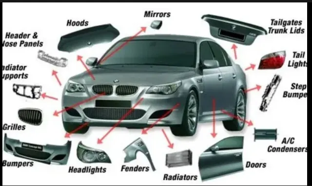
The role of plastic in the design and manufacturing of automotive vehicles has never been more essential, with stringent regulations and changing consumer habits driving demand for more affordable, lightweight, and fuel-efficient vehicles. Fuel efficiency has become one of the most important features in automotive vehicle design due to the rising fuel prices and stricter environmental regulations.
There are about 30,000 parts in a vehicle, out of which 1/3 are made of plastic. In total, about 39 different types of basic plastics and polymers are used to make an automobile. More than 70% of the plastic used in automobiles comes from four polymers: polypropylene, polyurethane, polyamides and PVC. Plastic has become one of the key materials required for the structure, performance, and safety of automobiles in recent years, with growth in plastic consumption being driven by light-weighting trends for fuel efficiency and consequently lower greenhouse gas emissions.
NEW PRODUCT DEVELOPMENT
New product development (NPD) is a process of taking a product or service from conception to market. The process sets out a series of stages that new products typically go through, beginning with ideation and concept generation, and ending with the product's introduction to the market.
CLASS A SURFACES
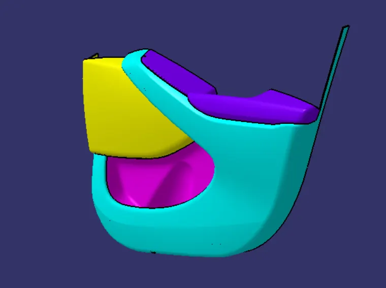
From the given data we have the Aesthetic component of class A surfaces which is given like lower substrate, arm rest, map pocket, map pocket with bottle holder.
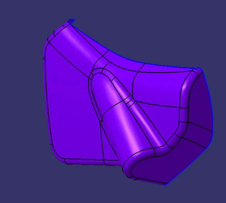
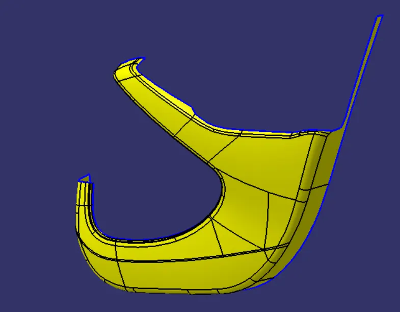
FIG:-BOTTLE HOLDER FIG:-LOWER SUBSTRATE
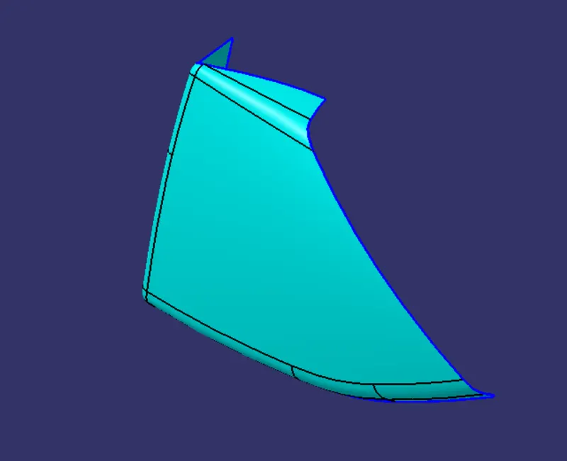
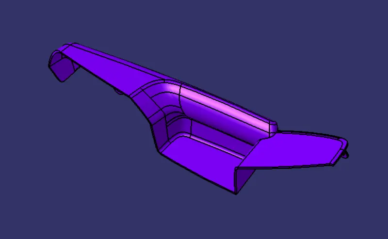
FIG:- MAP POCKET FIG:- ARM REST
TOOLING AXIS CREATION
Tooling direction is the direction the mould takes to make the part. It is basically the direction that the mould pulls apart. The mould is built in two separate pieces, a cavity side and the core side. The core pulls apart from the cavity and that is the Tooling Direction.
There are three methods for creating tooling axis
- Bisecting method
- Normal to surface
- X,Y,Z direction
Here we have using these methods for all components.
SIDE CORE AXIS
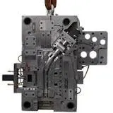
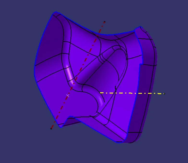
FIG:- TOOLING DIRECTION FOR BOTTLE HOLDER
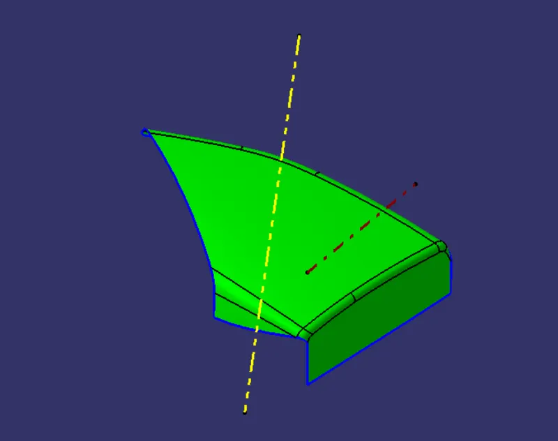
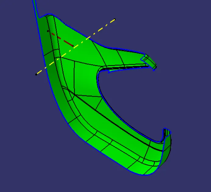
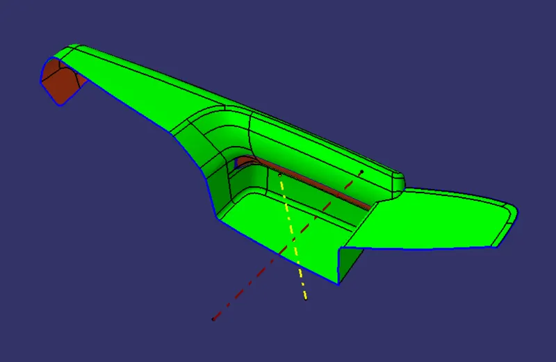
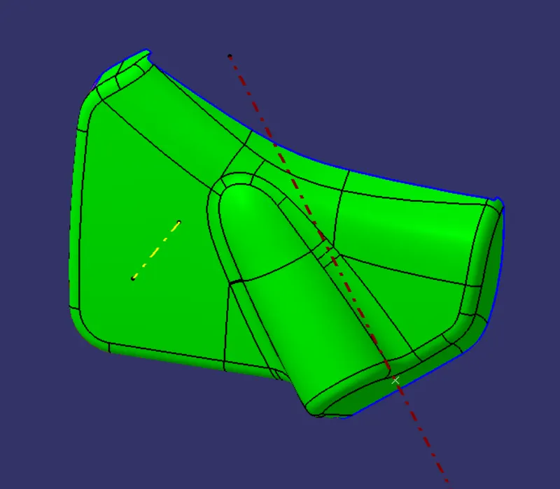
DRAFT ANALYSIS FOR CLASS A SURFACES
B SURFACE CREATION
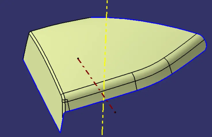
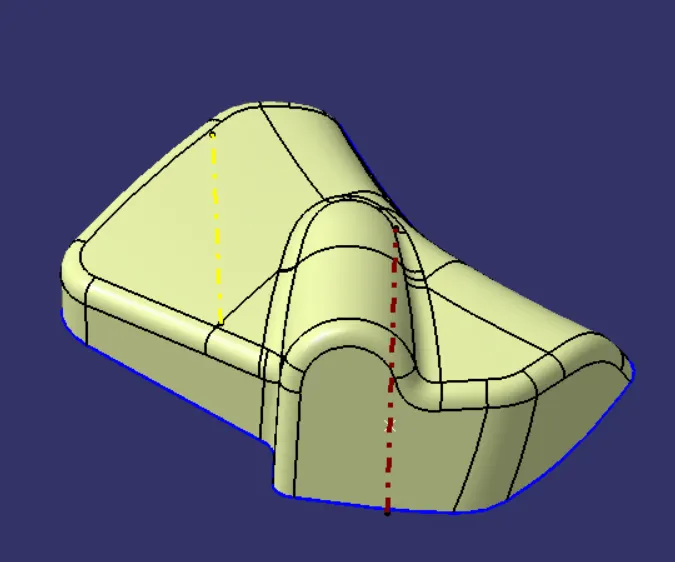
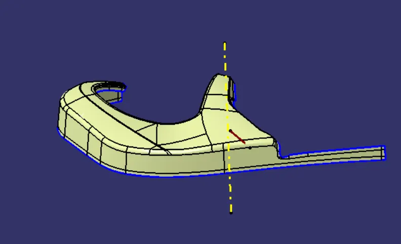
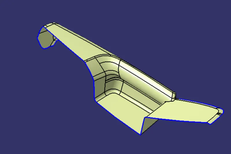
Class B surface is created directly offset and extrapolated for all parts.
CLASS C SURFACE
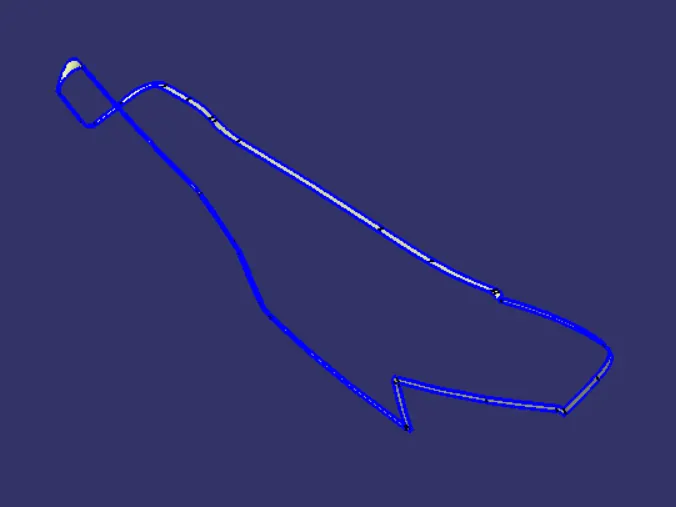
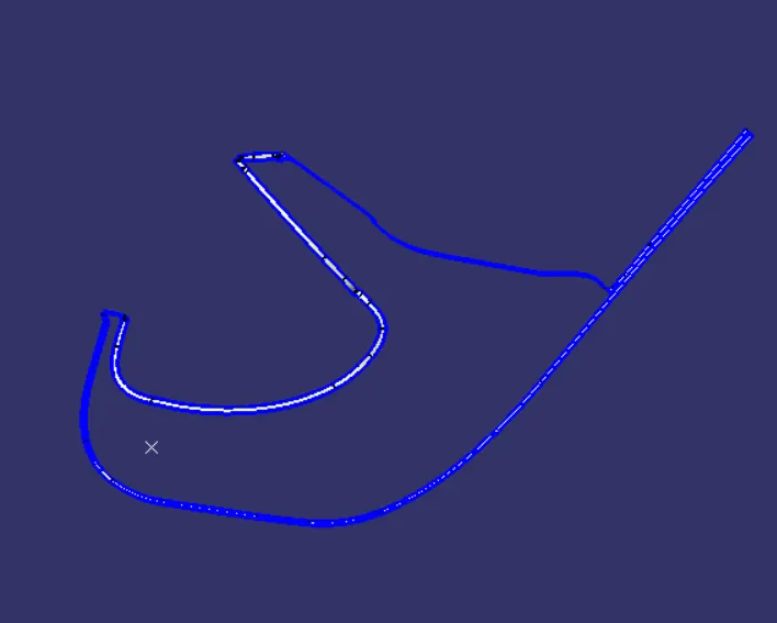
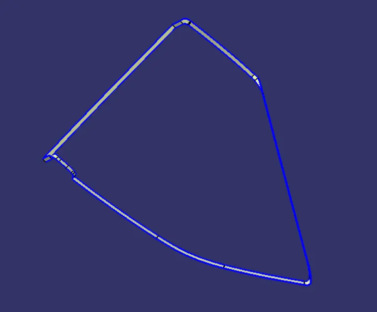
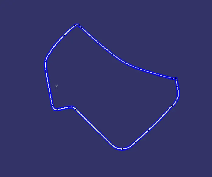
Class C surface created based on the tooling direction as well as surface reference. By using method is
- Creating swept surface
- Creating draft with tooling direction
- Creating multi section surface
HEAT STAKE CREATION
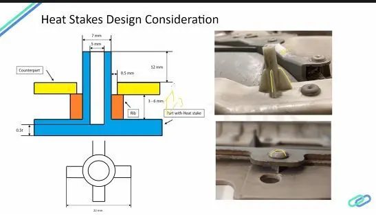
Heat staking also known as thermoplastic staking is the process of joining two dissimilar materials together. In heat staking we use local heating and cooling to raise the temperature of plastic components and allow plastic reforming to be carried out. This reforming can be used in a wide variety of applications.
MASTER SECTION FOR HEAT STAKE AND FLANGE
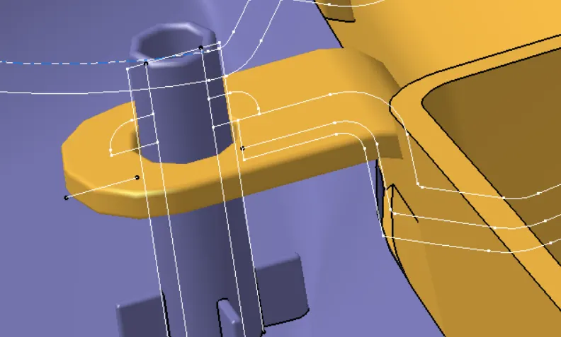
Procedure
- From given the referance curves in master section.
- Extract the curves then go to extruded.
- Finaly thickened the extrude surface.
- Give the fillet on the part which is given in the master section.
- Here we are created the stiffner ribs for heat stake support strength.
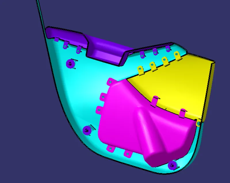
It is B-side attachment features
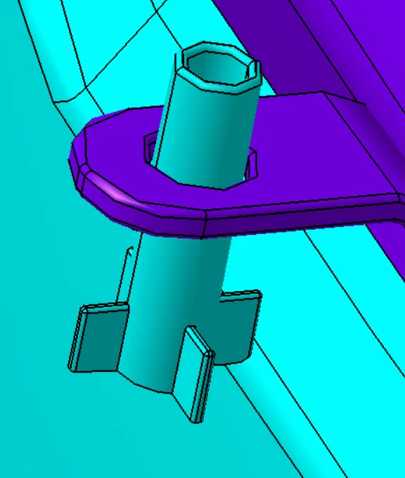
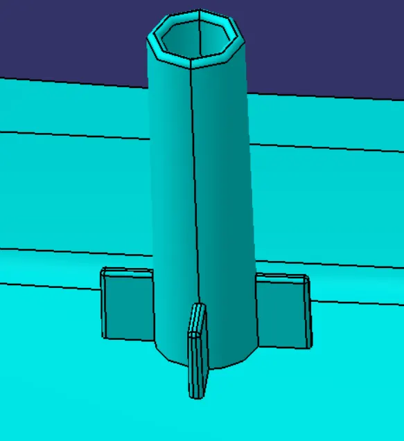
Attachment features created by all component on B-side
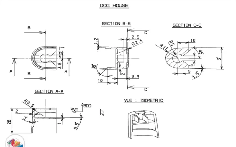
Create dog house and push pin for assemble with the door panel
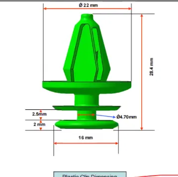
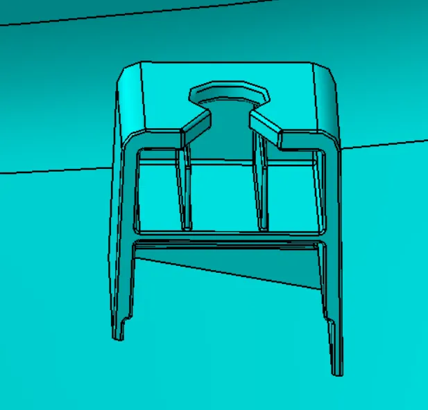
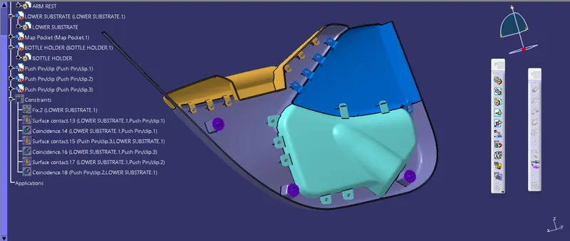
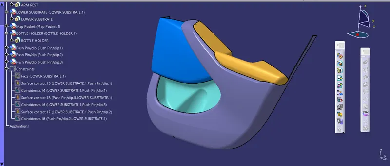
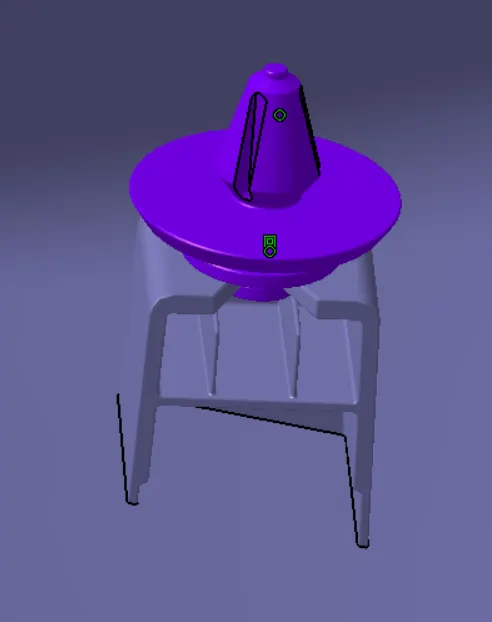
HOW TO ASSEMBLE THE PUSH PIN WITH ON DOG HOUSE
- To create the assemble file of top down approch.
- To insert the two different component seperated.
- To use manipulation command to required in our position.
- click the coincident constrain operation to select the axis of the two different component.
- To use contact constrain to fix the proper position.
- Finaly put the update all constrain.
Draft Analysis
In the injection molding process, plastic products are difficult to demold due to friction force between the cavity and products, thus, finished products might be deformed or damaged. Therefore, designers should add a draft angle to the geometric surface of products, which is parallel to the unloading direction, in order to help the products eject smoothly from the cavity.
This study uses CAD software as the main architecture to develop the function of automatic draft angle recognition and construction. The study is divided into three stages. First, the geometric features of products are identified in the CAD model by induced algorithm, then the quilts to be added in the draft design are determined and classified. Finally, draft angles are created in different ways according to different surfaces.
- Here we are using main tooling axis for draft analysis. Appeare teh green colour is performed by possitive draft.
- Here all the heat stake and dog house minimum draft is 0.5 deg.
- We are additionally created the two-way four-way locator.
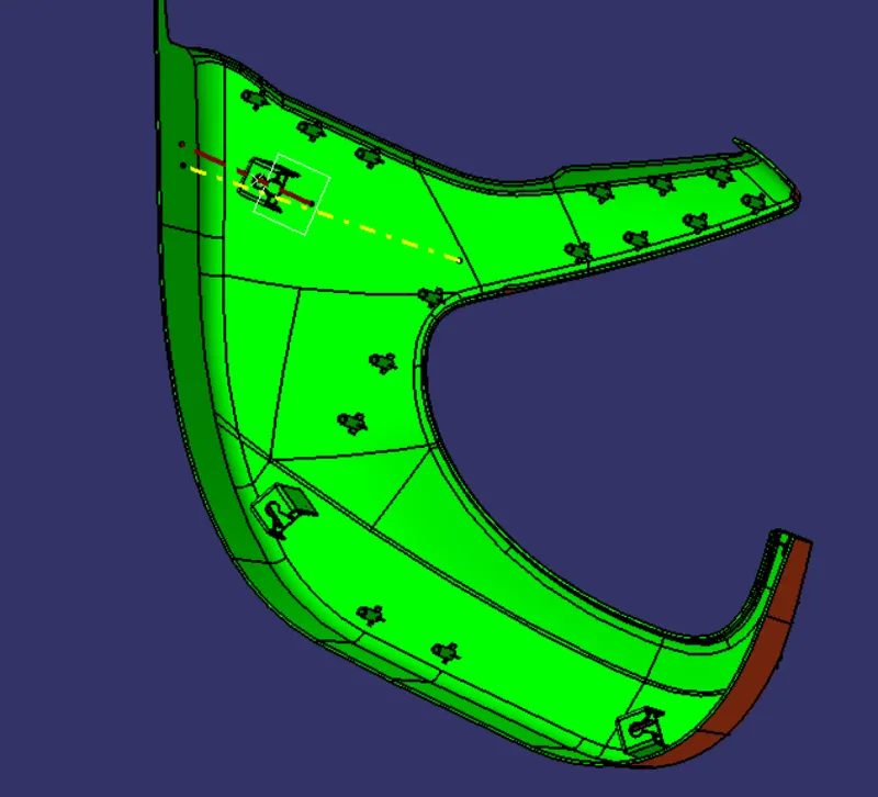
fig:- Draft analysis for Lower substrate
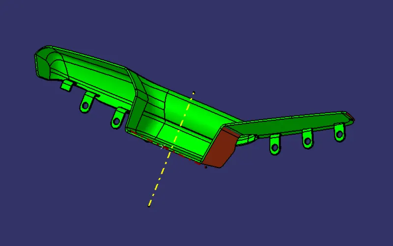
fig:- Draft analysis for Arm Rest
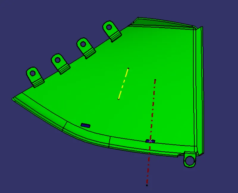
fig:- draft analysis for Map Pocket
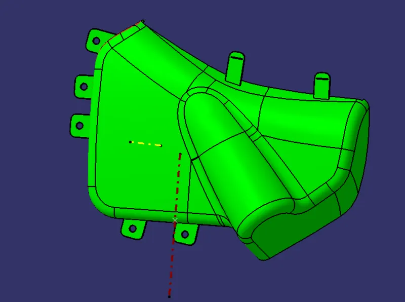
fig:-Draft analysis for Bottle holder
TREE STRUCTURE
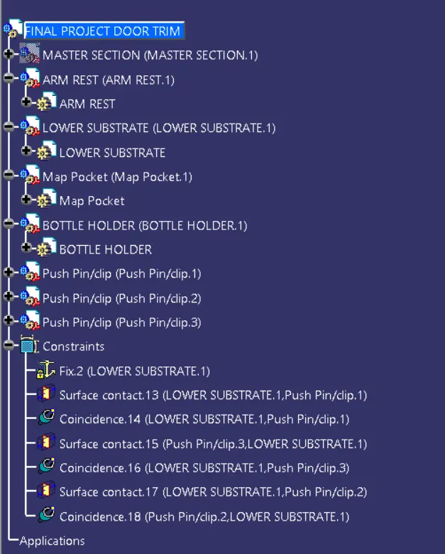
FINAL PLASTIC COMPONENT