Week 11 - Final project
FINAL PROJECT - ( DOOR TRIM )
AIM
To create the plastic door body with proper attaching features , from the given class A surface and master sections.
OBJECTIVES
- To creatre the thickened body .
- To create the tooling axis for each part body.
- To perform the draft analysis on each bodies.
- To make the required B side features for attaching.
DOOR TRIM PANEL
Next to the dashboard, the door trims are the interior parts that contains the most controls and attractive parts. As such there is neccesity fior balancing gap between parts , as well as an overall sense of unity between the numerous parts.
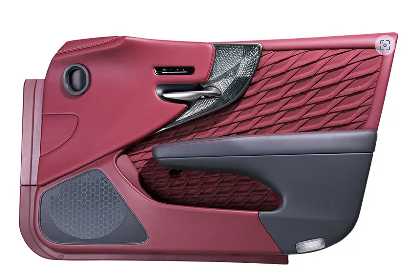
FIG :- DOOR TRIM
MAIN PARTS OF DOOR TRIM
- ARMREST
- MAP POCKET
- BOTTLE HOLDER
- LOWER SUBSTRATE
INPUT
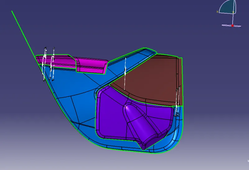
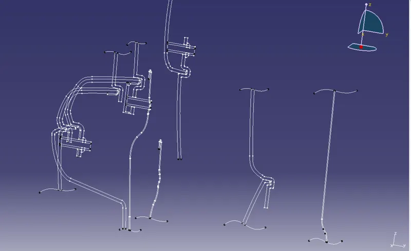
The master sections and class A surface for the all four component is given as an input.
STEPS IN CREATION OF DOOR TRIM
- Extract the required class A surface for the part body from the input. Create the tooling axis .Majo
- Perform the draft analysis on that surface.
- Create class B and class C surface.
- Create closed component.
- Develop the required B side features.
- Finally analyse the draft on tha final part body.
- Create the assembly file and nake the assemble of all the compoents includung pusshpins.
Class A surface
Class A surfaces are those aesthetic/free-form surfaces , which are visible to us (interior/exterior), and have an optimal aesthetic shape and high surface quality. The surfaces or regions which are visble nowdays are considered for class A modeling. It is one of the reasons why the umportance of class A modeling increasingf day by day. Majority of the time this term is used in plastic part designs.
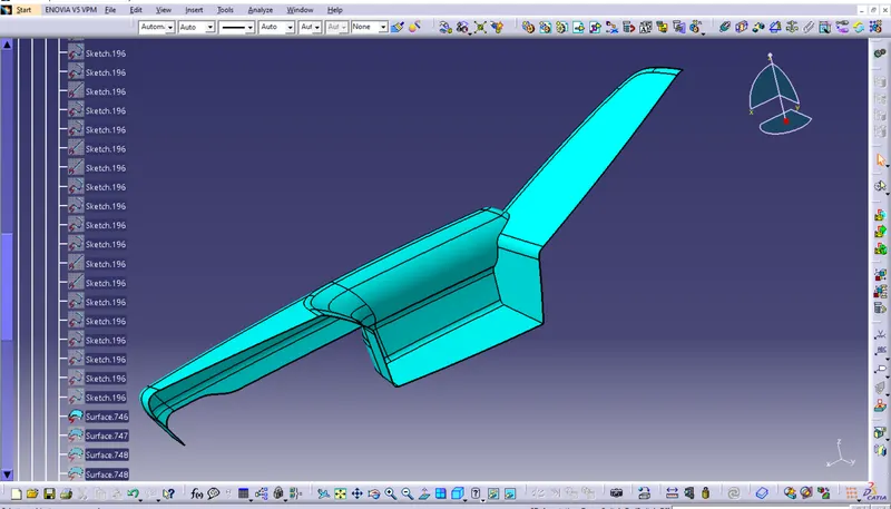
Here we hace 4 class A surfaces for 4 different components.
a) Armrest
b) Lowersubstrate
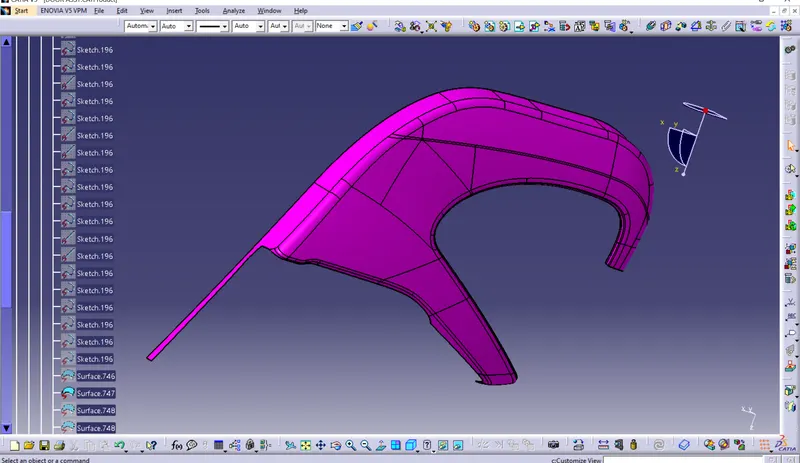
c) Map pocket
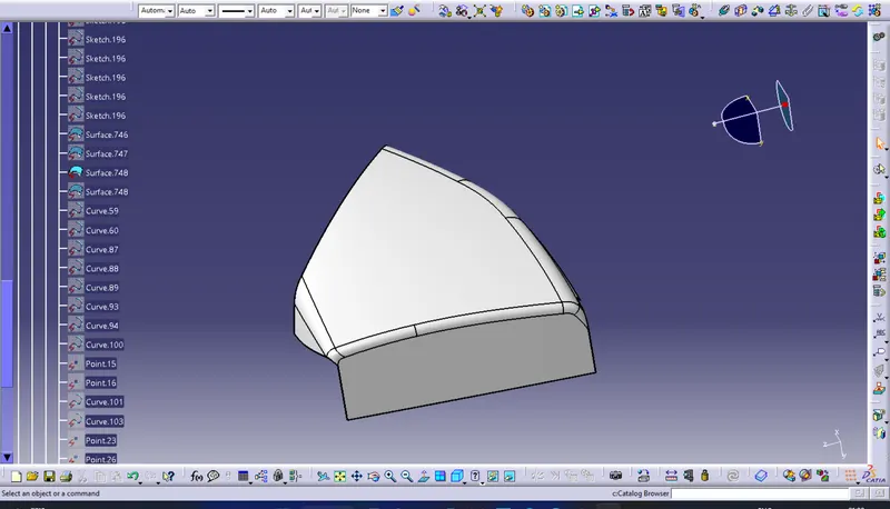
D) Bottle holder
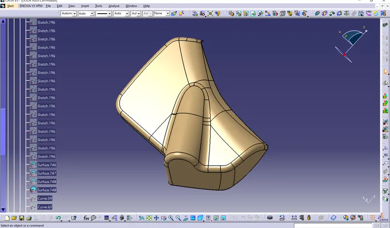
Tooling axis
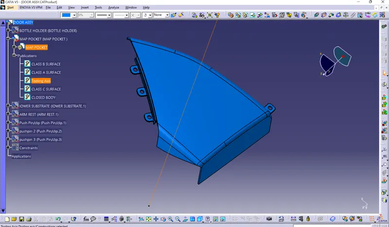
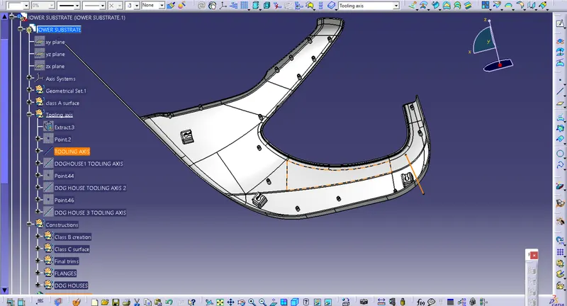
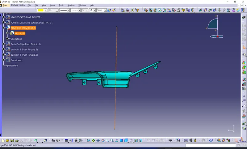
Tooling direction is nothing but the moving direction of core and cavity to make the component.That direction of the motion is projected in the axis thats called tooling axis.
Methods used in creation of tooling directions.
Bisecting method
- The two parallel pairs of surfaces are intersected by using planes.
- By using sketcher workbench one bisecting line is created between the two parallel faces, initially the faces are projected in sketcher.
- By the same way should create the another bisecting line between the other two faces.
- After that create the bisecting line between the both the lines .Thats out tooling axis.
Normal to surface
- The propable surface from the class A is extracted , That surface should hace proper flatness .
- Create the one point on that surface.
- By using line comment create the one line from the point in normal to surface direction. Thats our tooling axis .
X,Y,Z Axis method
- Check the surface with the all three direction for tooling .
- Find the suitable direction for the tooling .
- Extract the surface from that body and make a point on it.
- Create a line from that to the propable direction .
Tooling axis of bottle holder
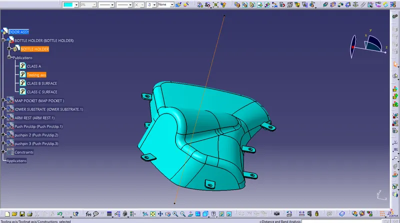
Tooling axis of mappocket
Tooling axis of lower substrate
Tooling axis of armrest
Class B surface
It is the invisible surface of the body, this surface is created with respect to class A surface . All the B side features (ribs,heatstakes,doghouses,screwboss) are developed on it.
Creation of class B surface.
- The given class A surface is offsetted to required valuof thickness.
- During the offset some blends and other surface parts are can't properly offested .
- By using different methods like subelements to remove,multiple extract and extrapolataion on edge the B side surface is get corrected.
- After correcting all the blends and surface the edges of B surface is should extrapolated to some value.
- This extrapolated surface is our Class B surface.
Class B surface of bottle holder
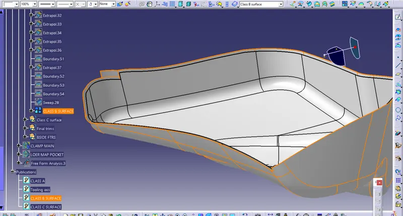
Class B surface of mappocket
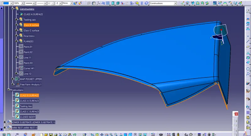
Class B surface of lowersubstrate
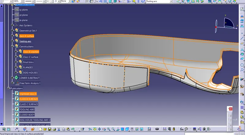
Class B surface of armrest
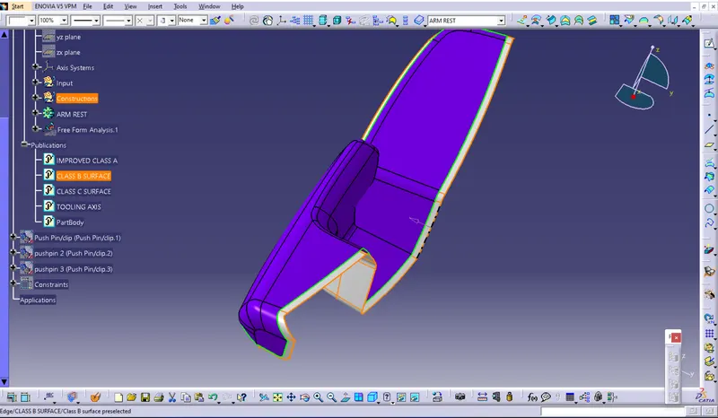
Class C surface
The class C finish allows more imperfections than class a or B . Class C is often specified for interior surfaces not readily visible , surfaces that will be covered by another part when assembled, or surfaces which the customer feels do not need to meet a high cosmetic finish. This class is generally used for parts or surfaces which are not viewd after installation or viewed by only service.
Creation of class C surface
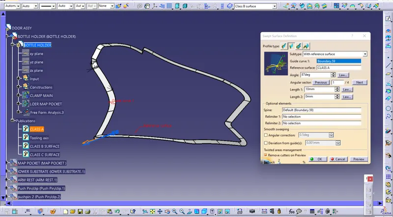
- The class C surface is created by using sweep method .
- Which faces are in perpendicular to the tooling direction that faces sweeped by daft direction method with minimum angle of 3 degree. This 3 degree should have outward direction because of avoiding the shrinkage on class B .
- Which faces are in parallel to the tooling axis that faces sweeped by reference surface with 90 degree .
Class C surface of bottle holder
Class C surface of mappocket
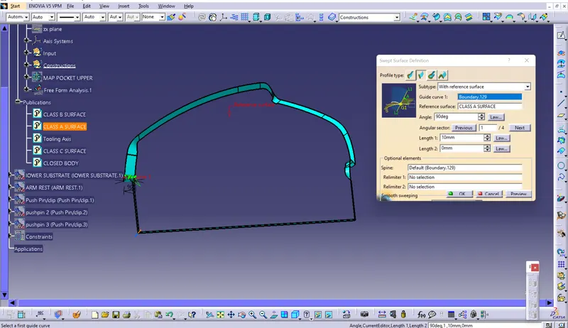
Class C surface of lower substrate
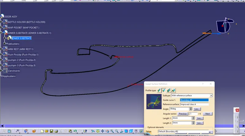
Class C surface of armrest
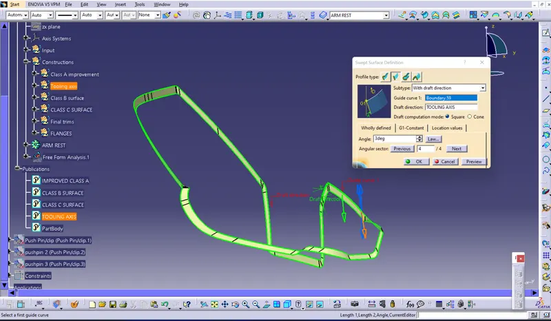
Closed body
Closed body is the combined from of all the three class A,B and C surfaces .There is no gap between each surfaces , there are perfectly joined together.After creating the closed surfae , in part workbench the suface is converted into solid body.
Closed surface of mappocket
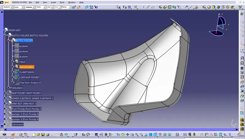
Closed surface of bottle holder
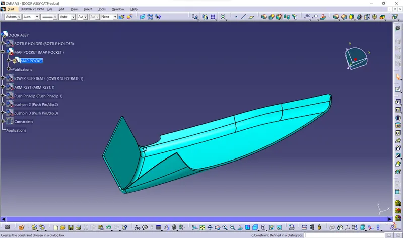
Closed surface og lower substrate
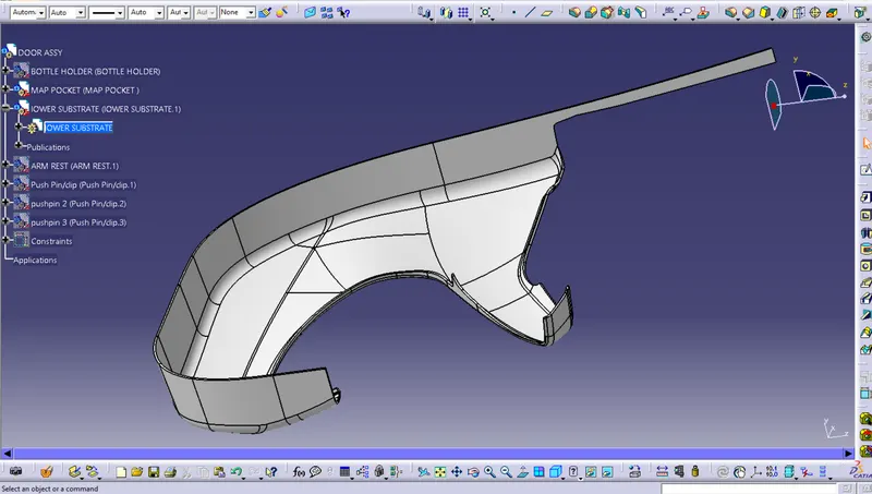
Closed surface of armrest
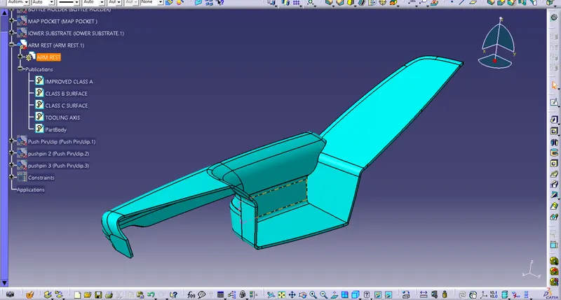
B side features
Some features are used to attaching and makes tge join between the two differentb parts. They are developed on the class B surface. Some B side features like stiffener, heat stakes, doghouses,screw bosses.
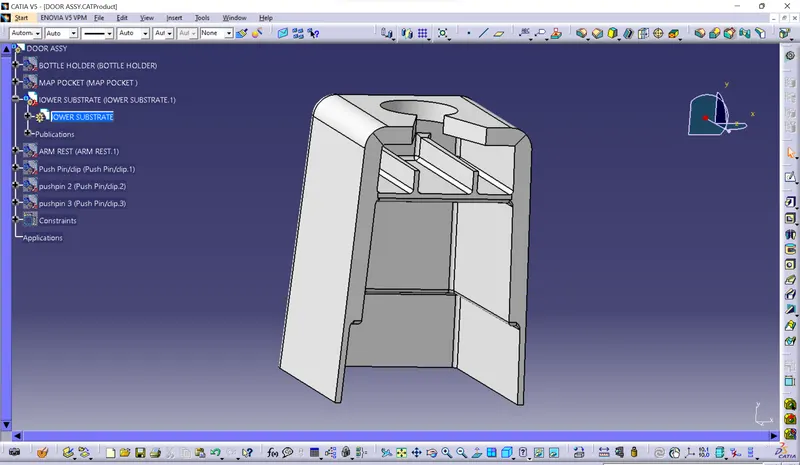
Dog house
Do house gives the additional height to the screw fixing from the B surface. and also screw and heat stakes can fixed perpendicular to that surface.
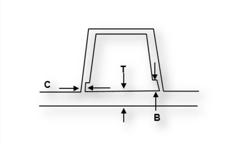
Here,
- 'C' is where the doghouse contacts back side of the surface that is B surface. Doghouse wall thickness at intersection at partwall 'C' should have 40% or less than main wall thickness.
- The height of section 'B' shpuld be 3.0mm-6.0mm .
- 'T' is the thickness of the component.
- The height of the doghouse should be >5T.
- Widh to height ratio is 2:1 is preferred.
- The draft angle of the doghose at outer surface is 1.5 degree to the maon tooling axis.
- The inner surface draft angle is should have 0.5 degree in side core axis.
Heatstakes
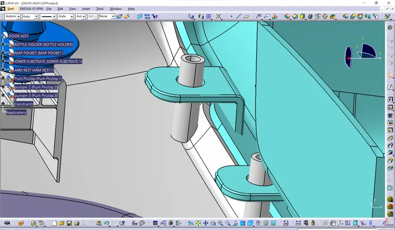
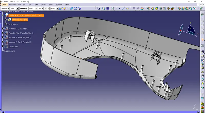
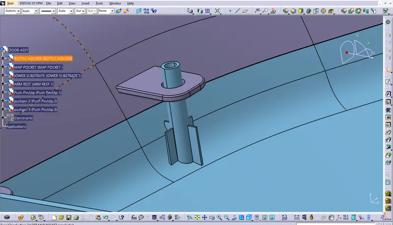
Heat staking in otger word is caled plastic welding . This type of join is used for the permanent joint. in manufacturing products with thermoplastic components, it is often necessary to join a thermoplastic to a part of dissimilar material,whether it be metal,a dissimilar plastic,or often material .
Th draft angle of heat stakes should have 0.5 degree to the main tooling.
Heat stakes on mappocket

Heat stakes on lower substrate
Heat stakes on mappocket
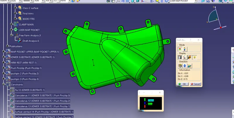
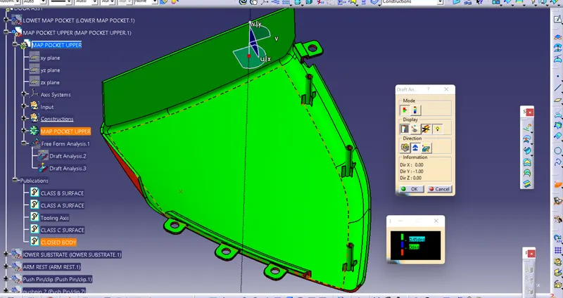
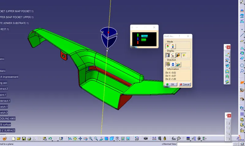
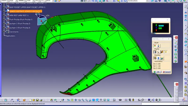
Draft analysis
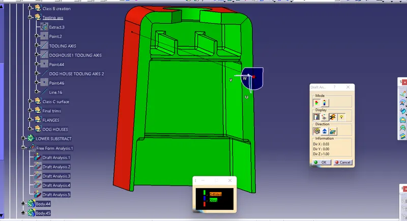
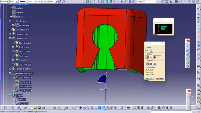
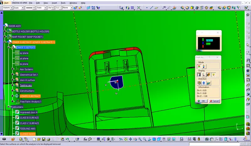
Draft analysis is technique used to analyze whether our prt model created in CAD is manufactiurable based on the draft condition applied. Here the part should easily removed from the mold.
Draft analysis on the part bodies
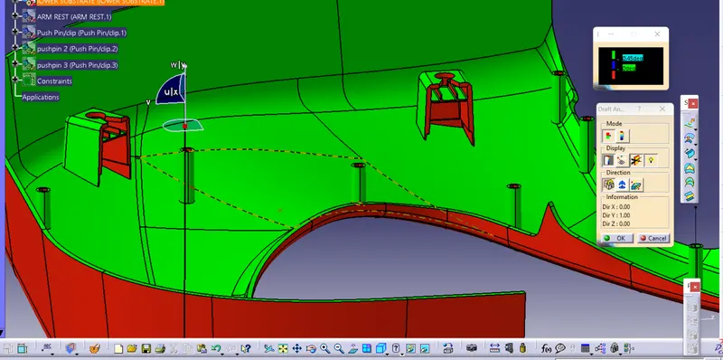
Doghouse draft analysis
The dog hosue hasve tha separate tooling axis . the dog houses are manufactured by the separate side core . The draft angle for the inner portion of the side core is 0.5 degree.
Dog house draft analysis in side core tooling axis
Assembly workbench
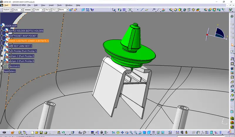
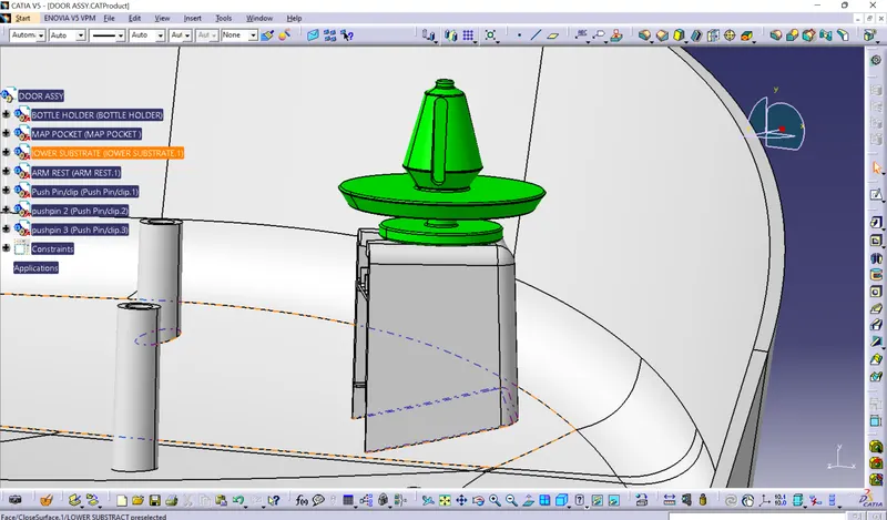
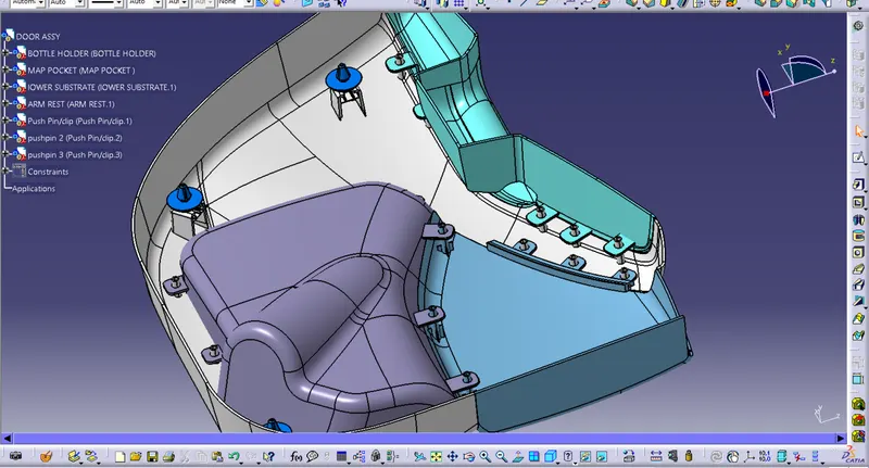
Assemble of pushpins
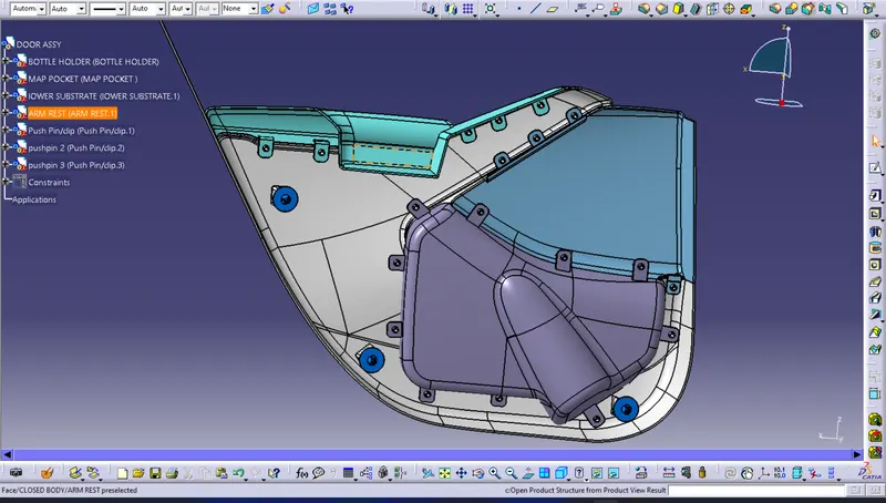
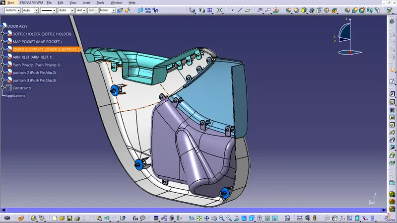
After creating the all 4 partbodies ,those are all inseterted into the assembly by using existing new component. By using proper contraints the part bodies will assembled at correct poistion.But here all the bodies are already assembled in the correct poistion. This assemble was made in class A surafces, only thing we need to add push pins at the top of the dog houses. First fix the lower substrate and lock that position. Then make the coincidence between the Dohouse upper hole axis to the pushpin center axis.After that make the surface constrains between dog house upper sirface and to the push pin required surface .

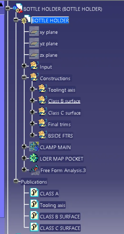
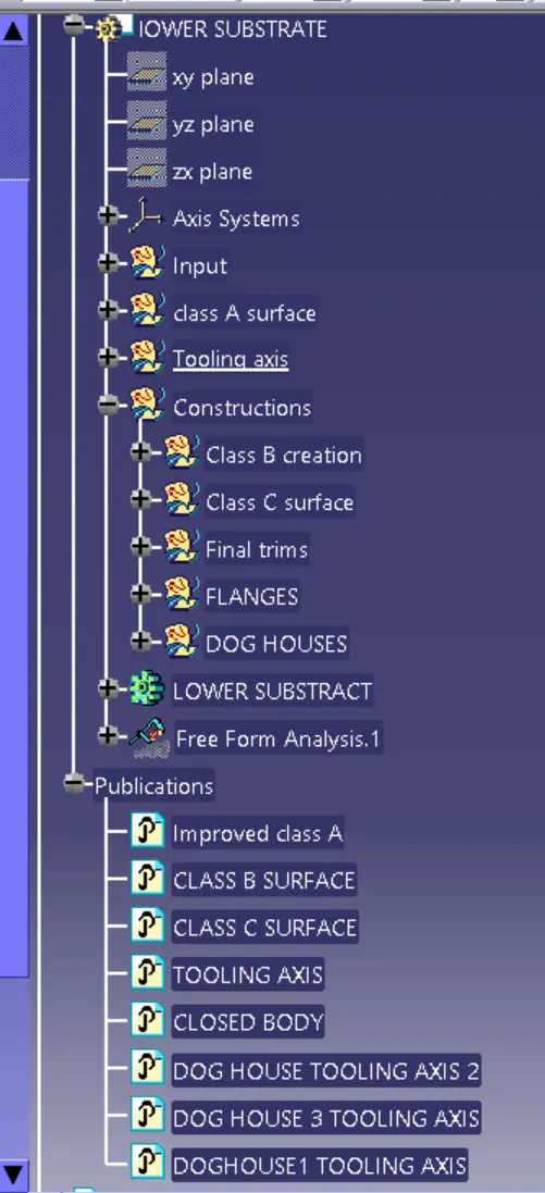
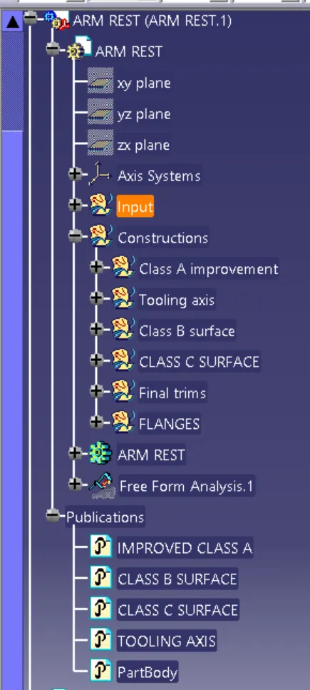
Tree structure of each bodies
Bottle holder
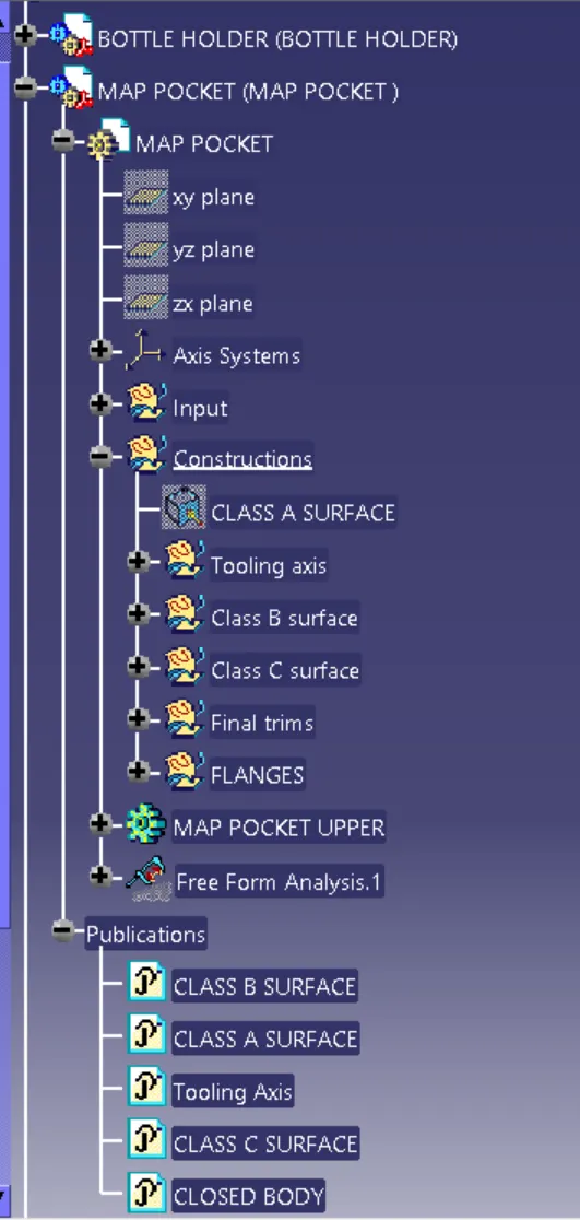
Mappocket
Lower substrate
Armrest
Assemble tree structure
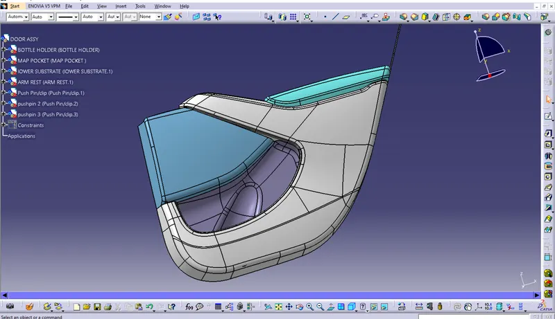
Door trim views
Conclusion
The final door trim body with required attachment features are created and the draft analysis was performed by using catia v5 software and the part file is attached .