Week 11 - Final project
DEVELOPMENT OF A DOOR TRIM PANEL
Automotive Plastic Trim: Trims refer to the style of plastic automotive interior and exterior parts. The interior of the car is represented by the plastic parts you can see. Examples include the dashboard, instrument panel, doors, furniture, and pillars. The exterior plastic parts of a car are called the exterior. ex: hoods, light assemblies, and bumpers.
Door Trim:
The wiring, power window motor and window regulator are covered by the door panel. It is fastened to the door's sheet metal frame. Based on the design of the sheet metal portion of the door, it is created differently. It has numerous useful features linked to it in addition to its attractive appearance, like an armrest, a bottle holder, a speaker attachment, etc. Older cars used to have cardboard door panels that were covered in upholstery that matched the rest of the inside upholstery. The majority of modern cars, however, feature plastic door panels. The primary components consist of kenaf, which is available all year and has high CO2 absorption qualities, and plant-derived plastic, both of which are environmentally beneficial.
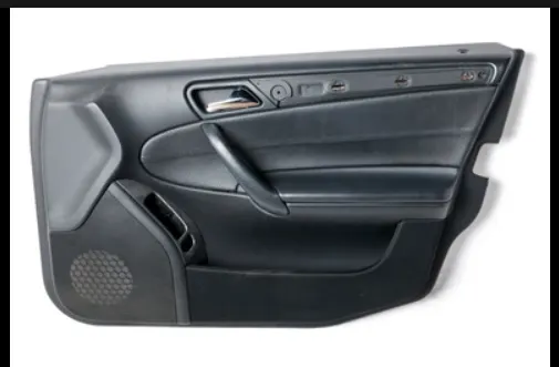
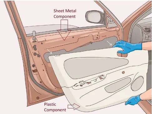
THE DOOR TRIM PANEL CONSISTS OF THE FOLLOWING COMPONENTS:
1. DOOR ARMREST
2. UPPER MAP POCKET
3. LOWER MAP POCKET
4. LOWER SUBSTRATE
5. UPPER SUBSTRATE
6. FLANGES
8. HEAT STAKES AND DOG HOUSE
Given Class A Surface:
A-class surfaces are those with excellent aesthetic shape and high surface quality that are free-form and aesthetically pleasing that are visible to us (interior/exterior). Mathematically speaking, class-A surfaces are those that have continuous curvature, provide the simplest mathematical representation necessary for the desired shape or form, and do not have any unwelcome wavering. Products are not only made with usefulness in mind, but also with special attention paid to the product's form and aesthetics, which can make someone want to purchase it.
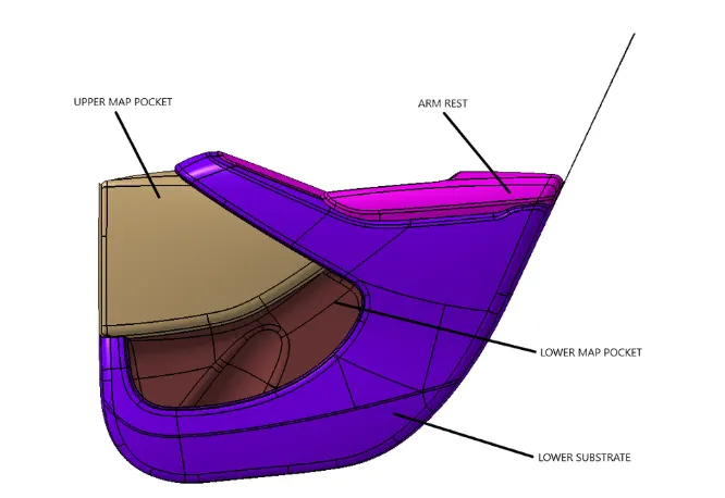
So we worked on this class A surface one by one.
1. DOOR ARMREST
- The central armrest in the front of the car, which frequently folds away depending on customer demand, frequently has storage space and occasionally even cup holders. Some also show where to find controls for the car's optional features, including the climate control or window motors.
STEP 1: Work on CLASS A SURFACE:
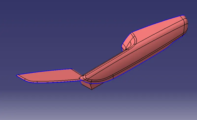
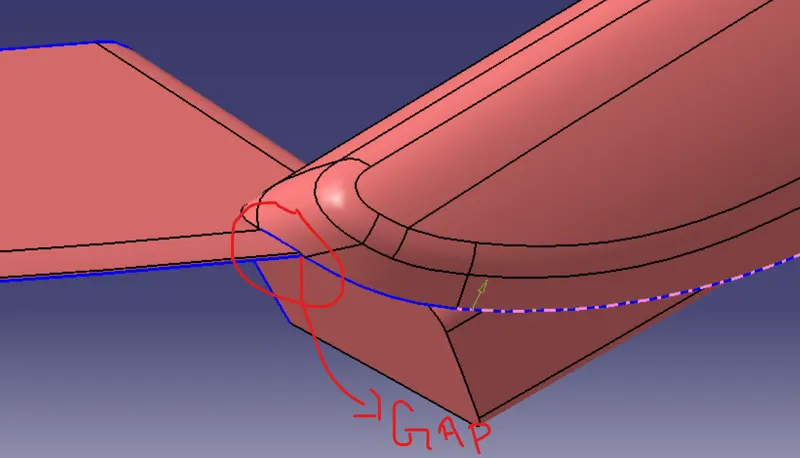
- As we see the boundary line from CLASS A Surface it means there is a gap present there so we have to work on that first. But as a plastic design engineers, we don't allow to change the class A surface but in this case, we have to improve the class A surface before creating the class B surface.
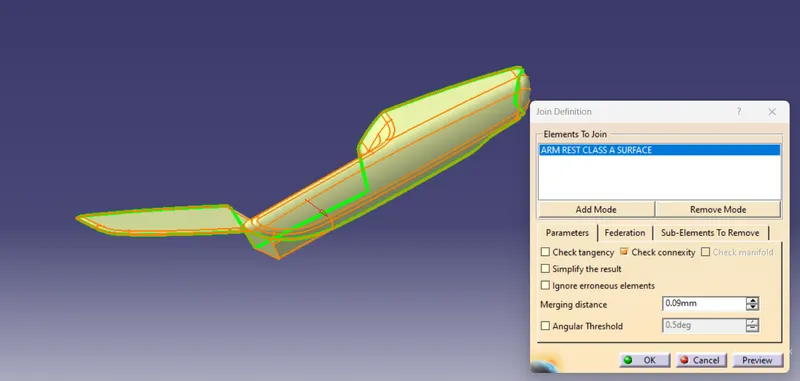
- Using the join command and increase the merging distance to 0.09mm.
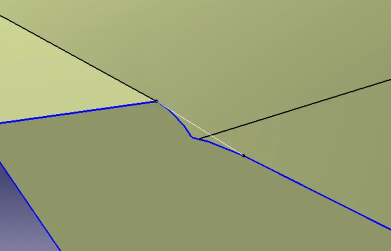
- Cut the small corner as shown in the below figure by creating a spline over the surface and use a split command to remove it.
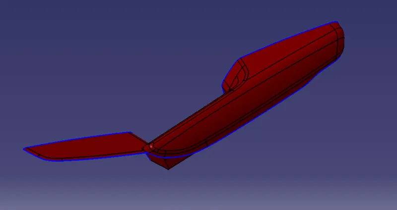
- Final improved Class A Surface:
STEP 2: CREATION OF TOOLING AXIS
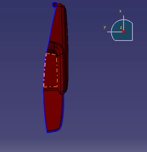
- Simply first visually check the Class A surface through the x, y, and z directions so that we can get the best tooling direction so that the part can easily come out from the mold. So we find that Z direction is the best direction for the tooling direction.
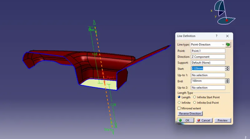
- Now extract the flat surface and create a point over the surface and draw a line through that point. That line is our tooling axis.
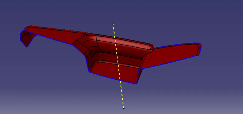
- Final Tooling Axis-
STEP 3: Creation of B Surface:
Class B surface are invisible surfaces and mostly don't have textures. This surface needs to be created according to the class A surface (one method is to offset the class A surface and then work on that surface). These surfaces have all features(Rib, boss, snap, etc) on the B-side surface only. We can also say that surfaces which are having TANGENT CONTINUITY are called class-B surface.
Procedure to create Class B surface-
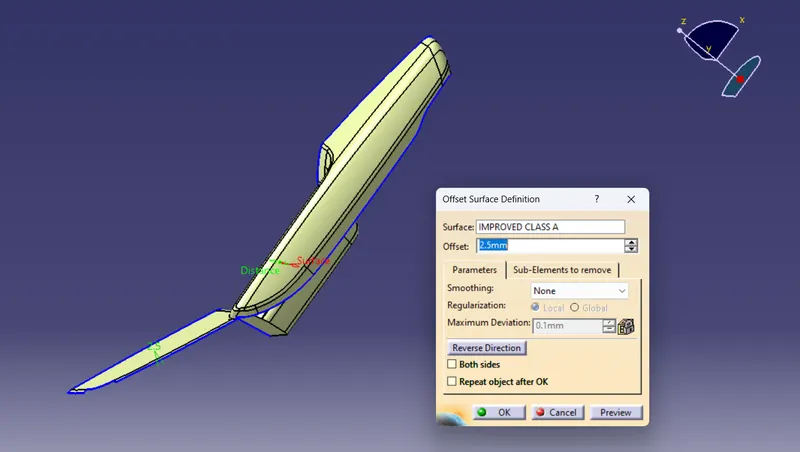
- First, we have to offset the class A surface by 2.5mm and after that, we have to fill the gap that is created due to offsetting the class A surface as shown below figure.
OFFSET BY 2.5mm
PATCHES/GAP FORM DUE TO OFFSET CLASS A SURFACE
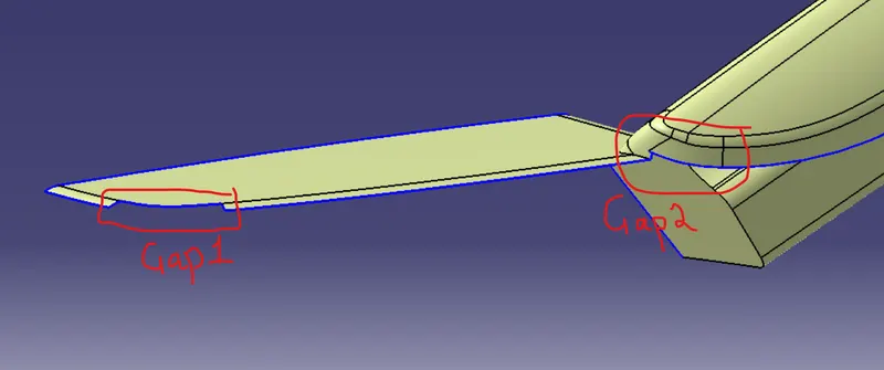
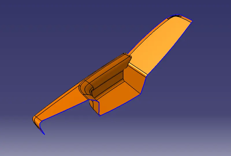
- To fill the gap/patches we used multisection, extract, extrapolate, trim, split, and sweep commands. The final B surface as shown below:
STEP 4: Creation of Class C surface
- Class C surfaces are those that can have tool marks, flashes, and other flaws without detracting from their look, functionality, etc.
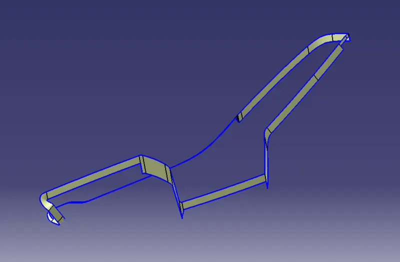
- The sweep command is typically used to produce a Class C surface.
- The border is first extracted, smoothed using the curve smooth command, and then using the sweep command according to the draft direction or reference to the surface using 3 degree and 87 or 93 degree respectively.
- Typically, the C surface does little more than cover the space between the A surface and the B surface by adding thickness.
STEP 5: FINAL JOIN AND TRIM
- Join Class A and C surface using the join command.
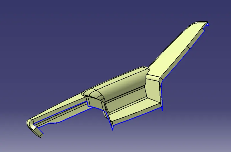
- Finally trim the class B surface with the above join to get the final arm rest surface.
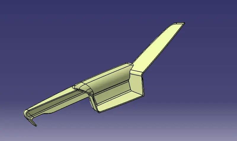
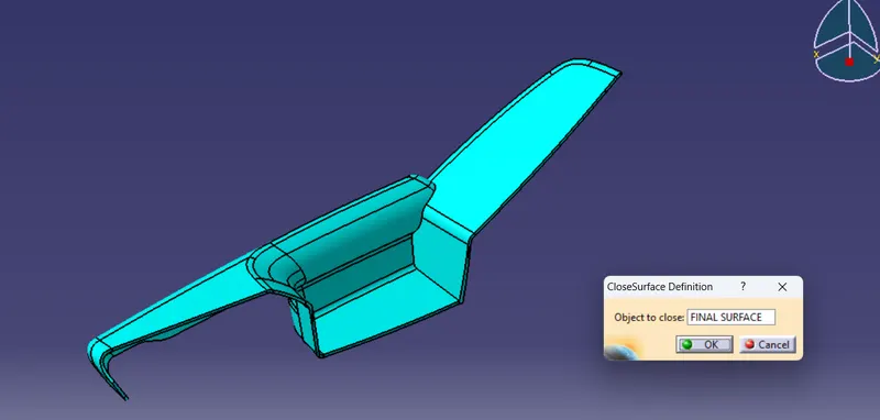
STEP 6: ARMREST SOLID BODY
STEP 7: DRAFT ANALYSIS
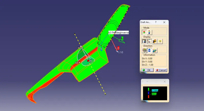
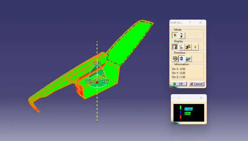
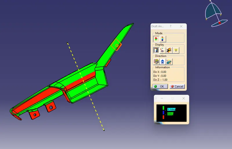
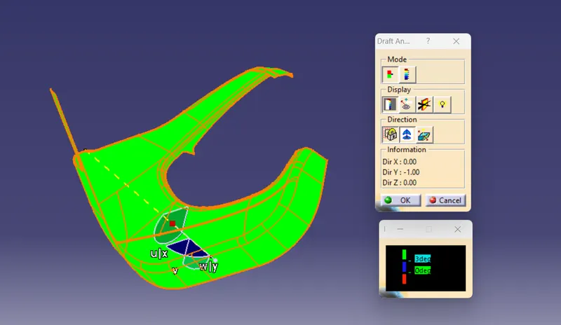
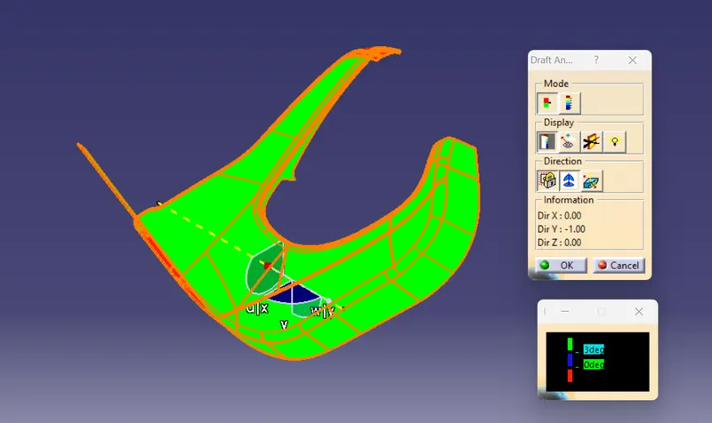
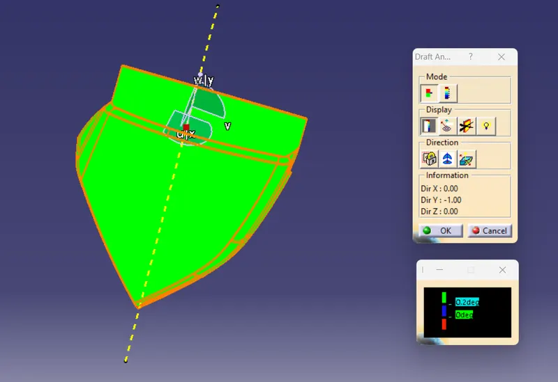
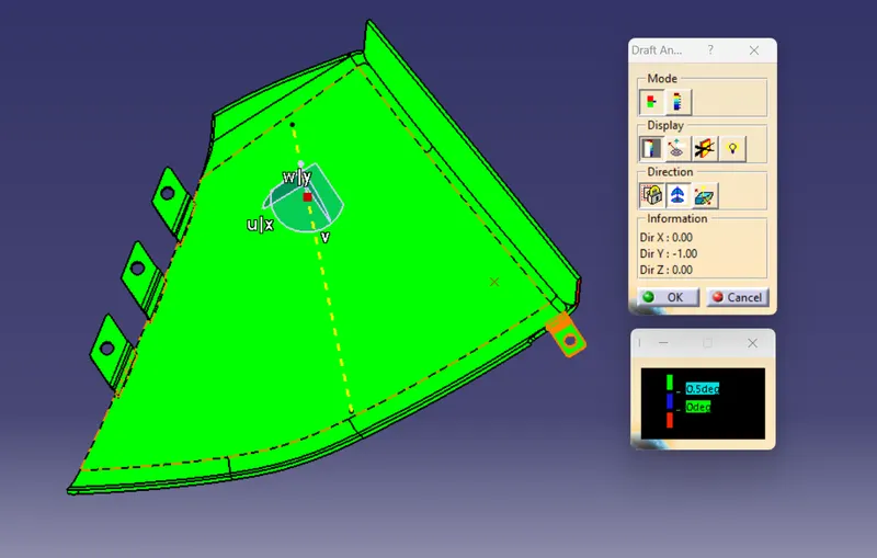
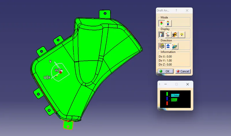
- You can determine whether the part you drafted will be simple to remove using the draft analysis command. In this kind of analysis, zones on the investigated element are identified by color ranges where the deviation from the draft direction at any given place corresponds to predetermined values.
- In this kind of analysis, zones on the investigated element are identified by color ranges where the deviation from the draught direction at any given place corresponds to predetermined values. These values are expressed in the unit as specified in tools >option > general > parameters > unit tab.
You can modify them by clicking on their corresponding arrow or by entering a value directly in the field.
PROCEDURE TO PERFORM DRAFT ANALYSIS
1.Select a surface.
2.Click the (feature) draft analysis icon:
3.Double-click on the value in the color scale to display the value edition dialog box.
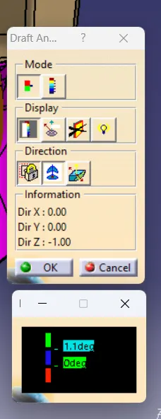
Draft Analysis of Class A surface
STEP 7: CREATING B-SIDE FEATURES
FLANGE CREATION:
1. FOLLOW THE MASTER SECTION for the proper dimension of the flange.
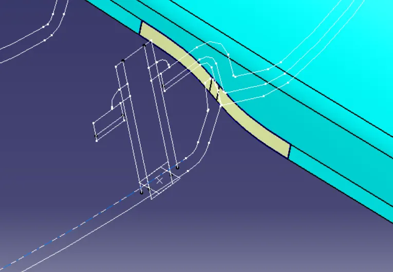
2. USING THE COMMAND LIKE EXTRACT, SWEEP, EXTRAPOLATE, OFFSET, TRIM, AND EXTRUDE WE FORM THE FLANGES
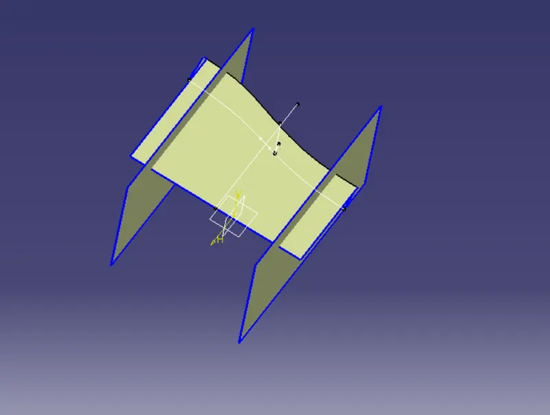
3. USING THICKNESS COMMAND (2.5 mm THICK) we form our final flange
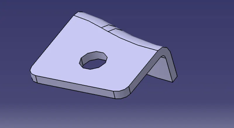
So we provide a total of 4 flanges over the armrest so that it can easily bear the force exerted by the arm of the human body as shown below figure.
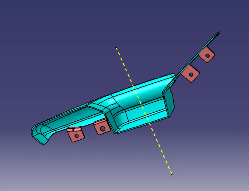
DRAFT ANALYSIS OF FINAL COMPONENT WITH B-SIDE FEATURES
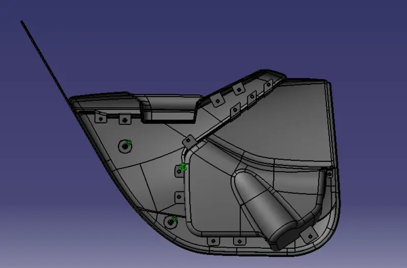
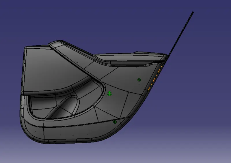
LOWER SUBSTRATE
Step 1: Taking Input as a Class A Surface.
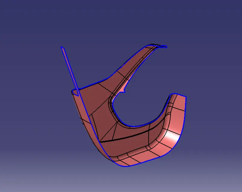
Step 2: Creation of Tooling Axis
- We follow the same steps that we followed earlier in the creation of the tooling axis for the armrest.
- Here y direction is the best direction for the tooling axis.
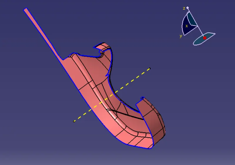
STEP 3: CREATION OF CLASS B SURFACE
OFFSET CLASS A SURFACE BY 2.5mm AND WORK ON THE PATCHES WITH THE SAME COMMANDS.
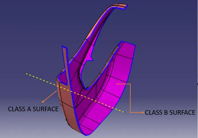
STEP 4: CREATION OF CLASS C SURFACE
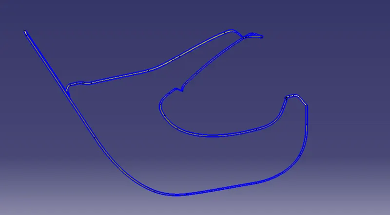
STEP 5: FINAL JOIN AND TRIM
JOIN A & C SURFACE
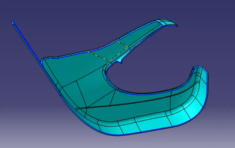
FINAL TRIM
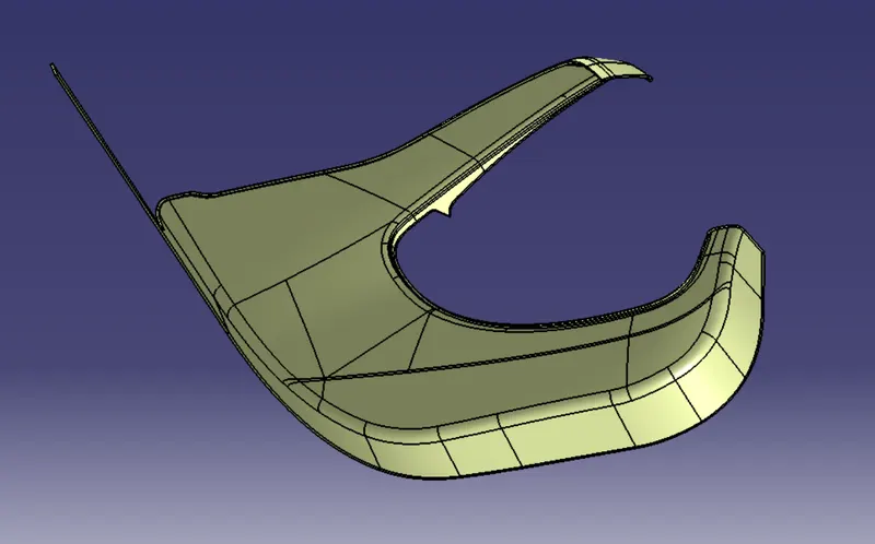
STEP 6: SOLID LOWER SUBSTRATE
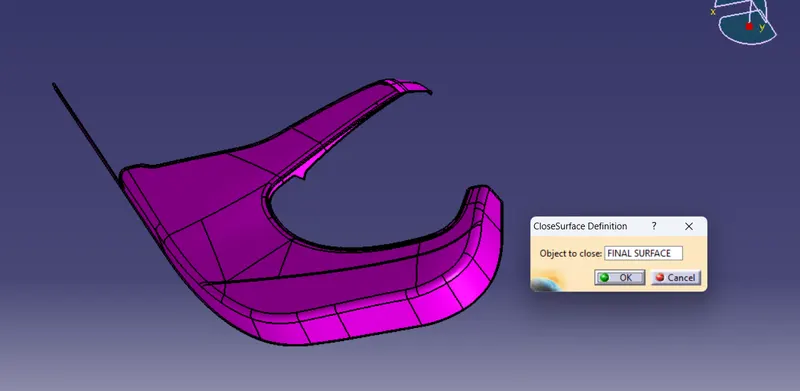
STEP 7: DRAFT ANALYSIS
DRAFT ANALYSIS OF CLASS A SURFACE
DRAFT ANALYSIS OF FINAL CLOSED SURFACE
STEP 7: CREATING B-SIDE FEATURES
1. CREATION OF HEAT STAKES
In the automobile industry, heat stakes are most frequently used to fuse plastic to various substrates. To grab or lock another material, such as plastic or metal components, heat staking is an assembly technique that allows control over the melting and reformation of plastic bosses or studs.
- The dimension of the heat stake was taken from the given master section by using measures between commands.
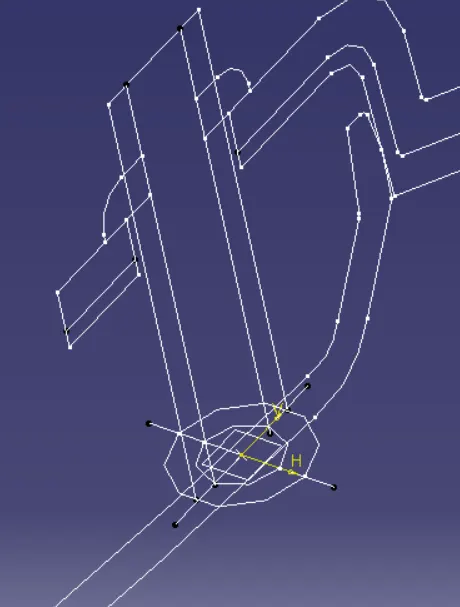
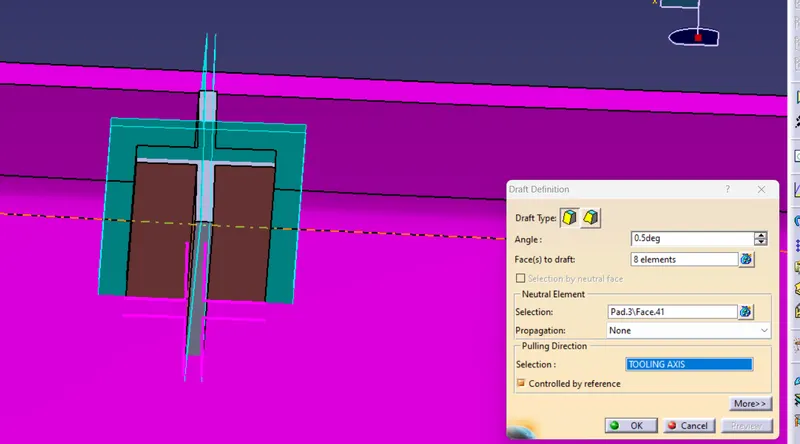
- Create a sketch of the heat stake then use the pad, draft, and edge fillet commands.
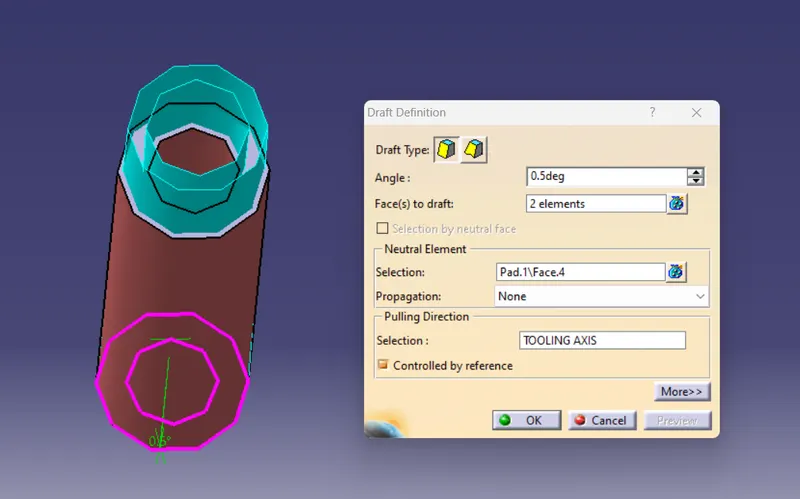
- Provide a draft on both sides of the face around 0.5 degrees as shown below.
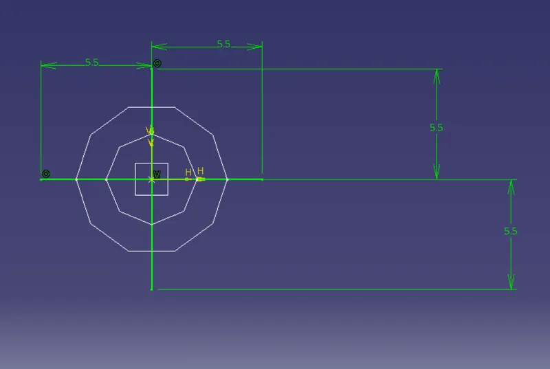
Sketch of ribs-
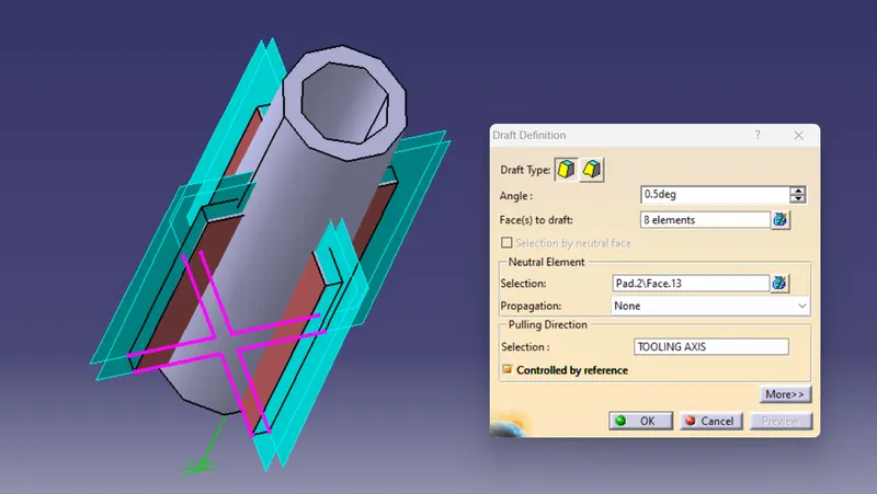
At ribs, we provide a draft of 0.5 degree.
- At last, we provide an edge fillet on every sharp edge of 0.25 degrees.
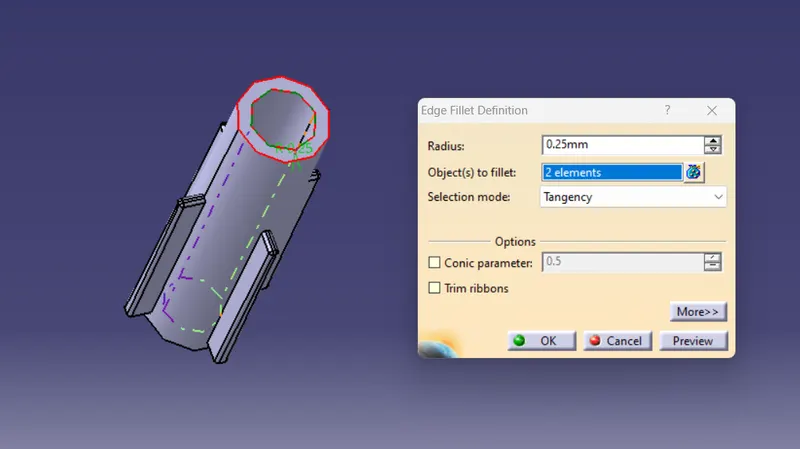
Final heat stake as shown below:
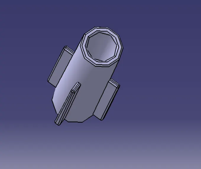
Similarly creating 12 more heat stakes just taking the same dimensions and steps-
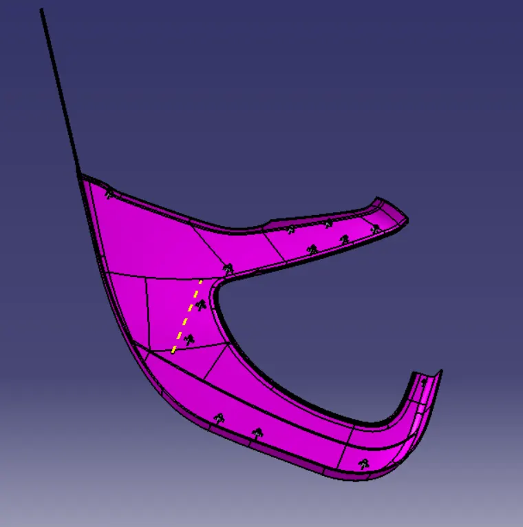
2. CREATION OF DOG HOUSE
The dog house is an engineering element used in the creation of plastic trim. Dog houses are a supporting element. In order to strengthen their strength, snaps, locators, and other engineering features are occasionally put on them. Draft analysis is applied to dog houses to reduce component breakage during component ejection from the mold cavity. On the B-surface, dog houses and other engineering components are constructed.
FOLLOWING THE DESIGN CONSIDERATION OF THE DOG HOUSE AND LOWER RIB
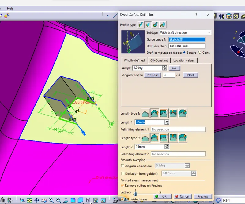
- The draft angle should be less than 0.5 degrees for the inside surface of the dog house and 1.5 degrees for the outside surface.
- The edge fillet angle should be 3 degrees for outside edges and 0.25 to 1 degree for inside edges
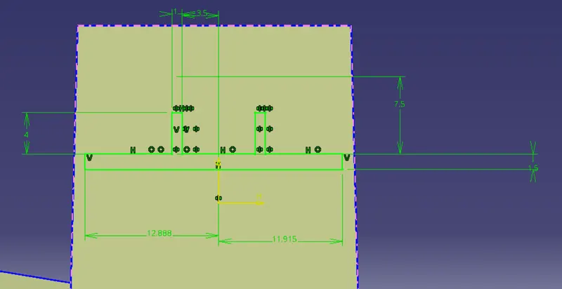
- The edge fillet for the ribs is 0.25 degrees and the draft angle should be less than 0.5 degrees.
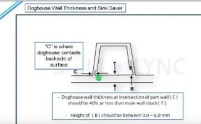
Procedure to create a dog house:
- First, extract the surface and create a point over it. Using that point create a plane and draw a sketch.
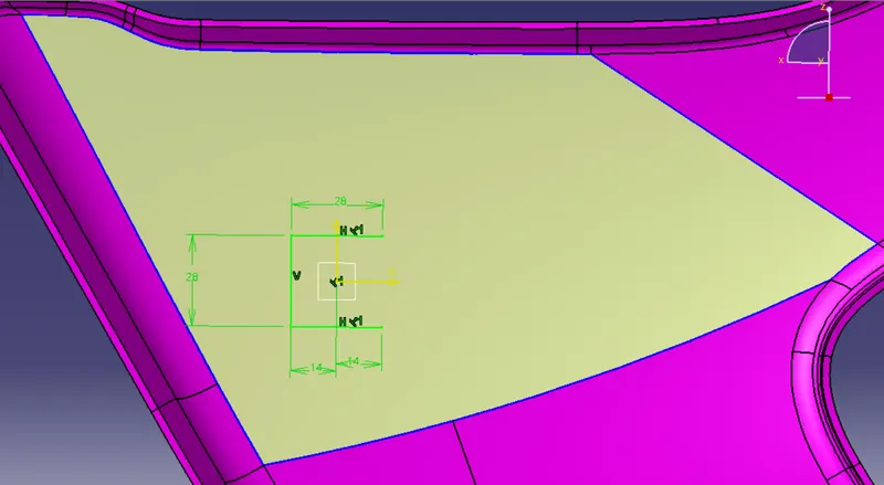
- Using a sweep command by giving 1.5 degrees along the main tooling axis to form a surface
- Creation of rib
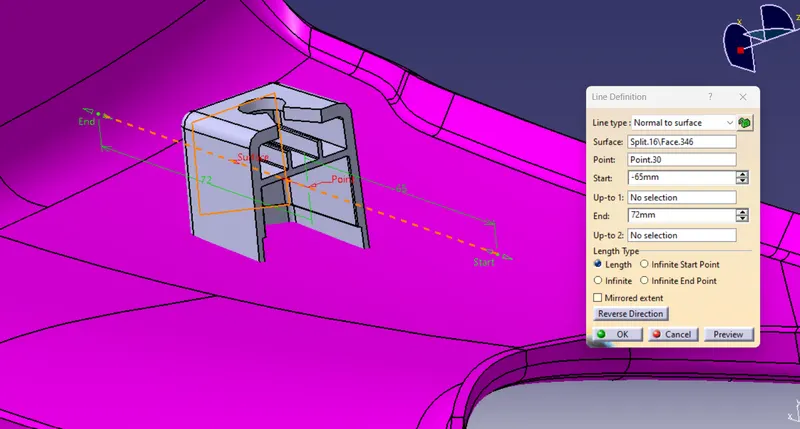
- Creation of side core axis
- Final dog house
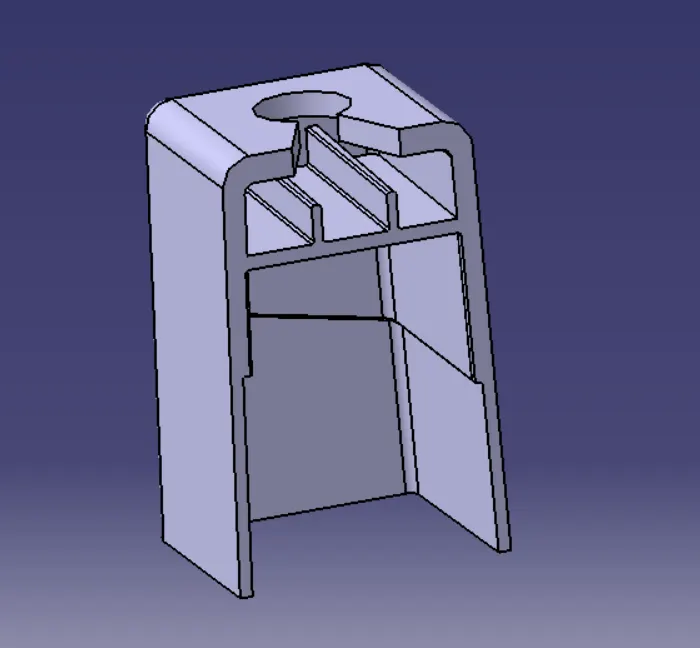
- Draft Analysis of dog with the main tooling axis-
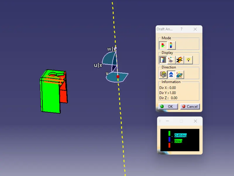
- Draft Analysis of dog with the side tooling axis-
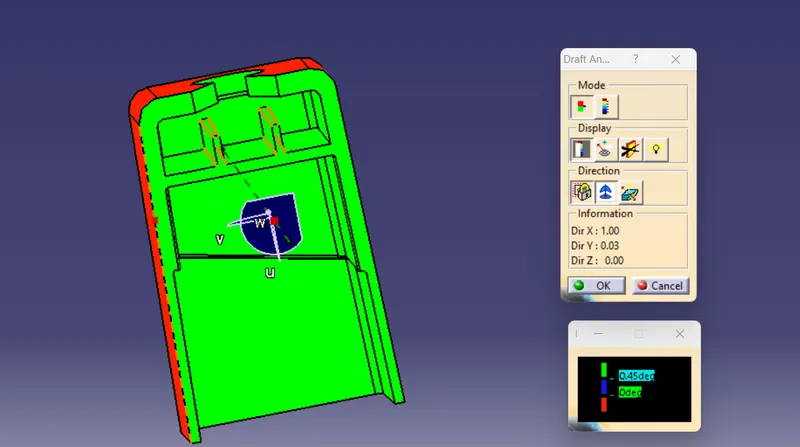
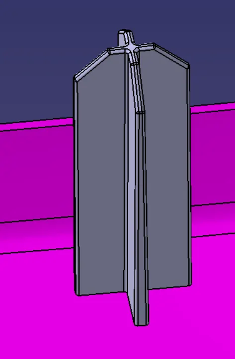
3. Creation of 4 Way Locater
- Create a sketch:
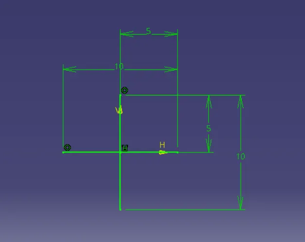
- Use Pad command with 1mm thickness and then provide chamfer, edge fillets, and draft to the locater.
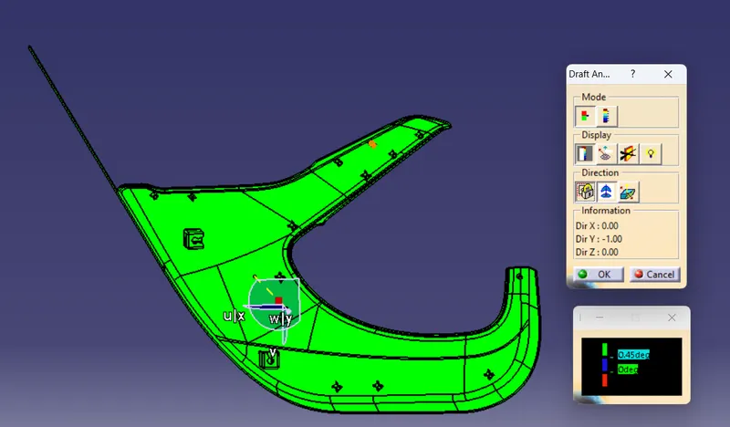
Draft analysis of Final Closed Surface with all B-Side Features
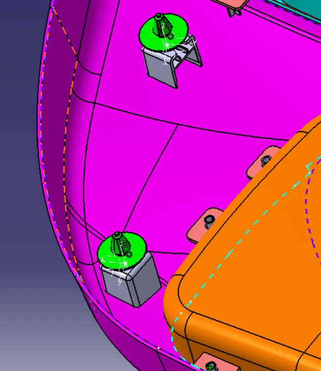
STEP 8: USE THE ASSEMBLY WORKBENCH TO PLACE THE PUSH PIN CLIP OVER THE DOG HOUSE
- Take input as Push pin clip
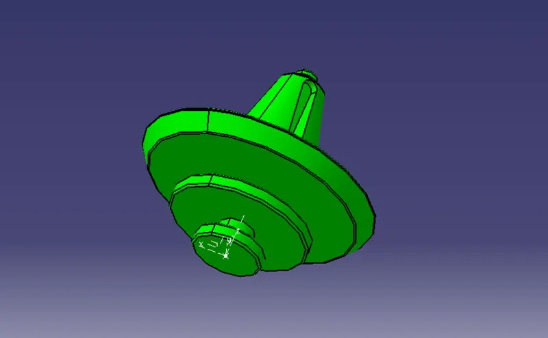
- Fix lower substrate using FIX Command in the assembly workbench
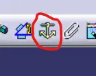
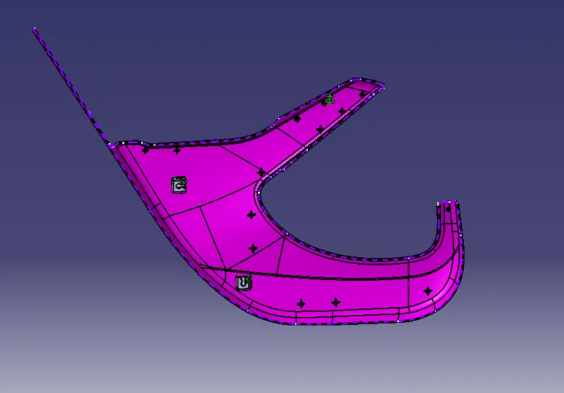
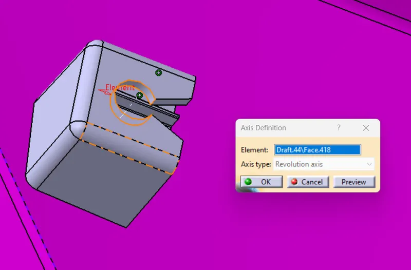
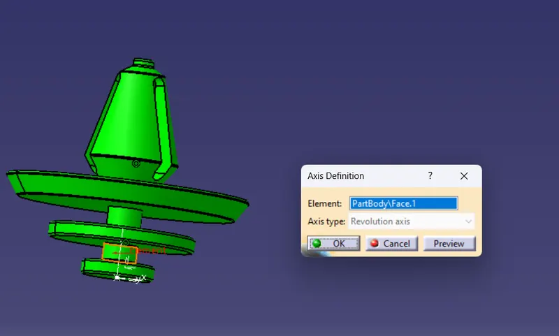
- Create a reference axis above the dog house and for the push pin clip so that we can use coincide command to place the push pin clip over the dog house.

3. UPPER MAP POCKET
By projecting a section outwards towards the passenger compartment and then providing a separate panel attached to the rear outboard surface of the trim panel, map pockets can be integrated into the door trim panel as a whole. This particular map pocket extends into the passenger area. A recessed map pocket, for example, can also be created within the door assembly so that the storage compartment of the map pocket is typically situated between the trim panel and the outside metal panel of the car door. The entrance to the map pocket is designated by an aperture in the door trim panel. These kinds of map pockets typically consist of a separate map pocket assembly that is attached to the back of the trim panel. The storage compartment is defined by the map pocket assembly, which is made up of a front section and a separate rear portion that are joined together. The rear part creates the map pocket assembly's back wall. A lower front wall and a pair of side walls are defined by the front part. The area above the lower front wall is typically open to allow access to the map pocket's storage space. The map pocket assembly is then attached to the rear surface of the door trim panel such that the opening of the map pocket is generally aligned with an opening formed in the door trim panel.
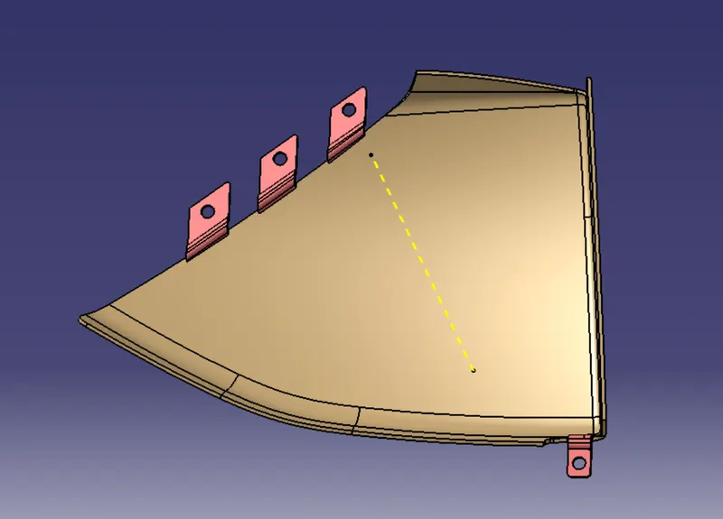
So the steps are the same for this also first create a tooling axis then offset the Class A surface by 2.5mm so that we can get the Class B surface. After creating the Class B surface we work on the Creation of the Class C surface using the sweep command at an angle of 3 degrees outwards with respect to tooling direction. In some areas, the 90-degree sweep was applied.
CLASS A SURFACE
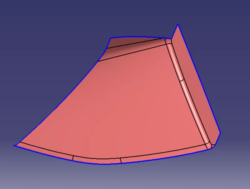
TOOLING AXIS (along y direction)
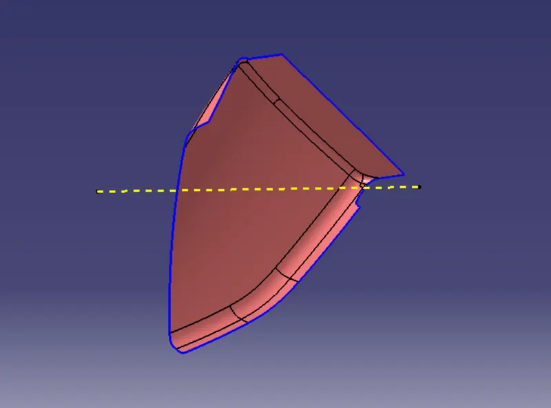
CLASS B SURFACE
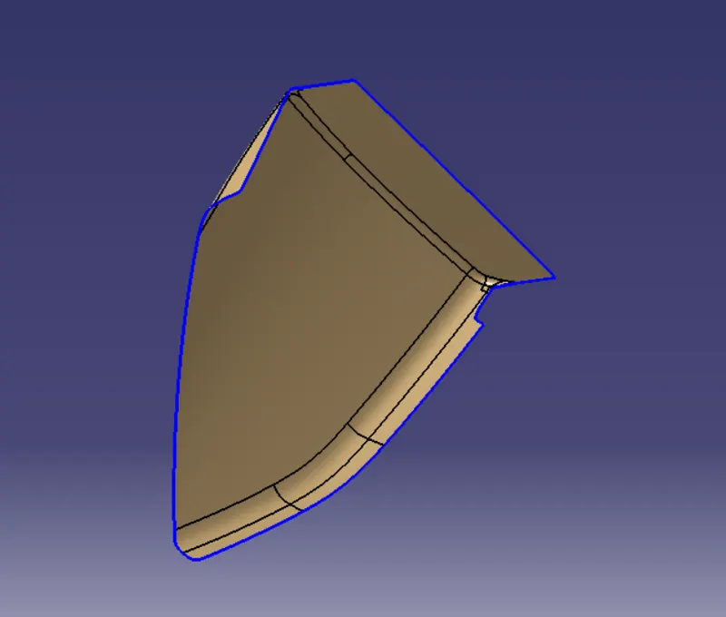
CLASS C SURFACE
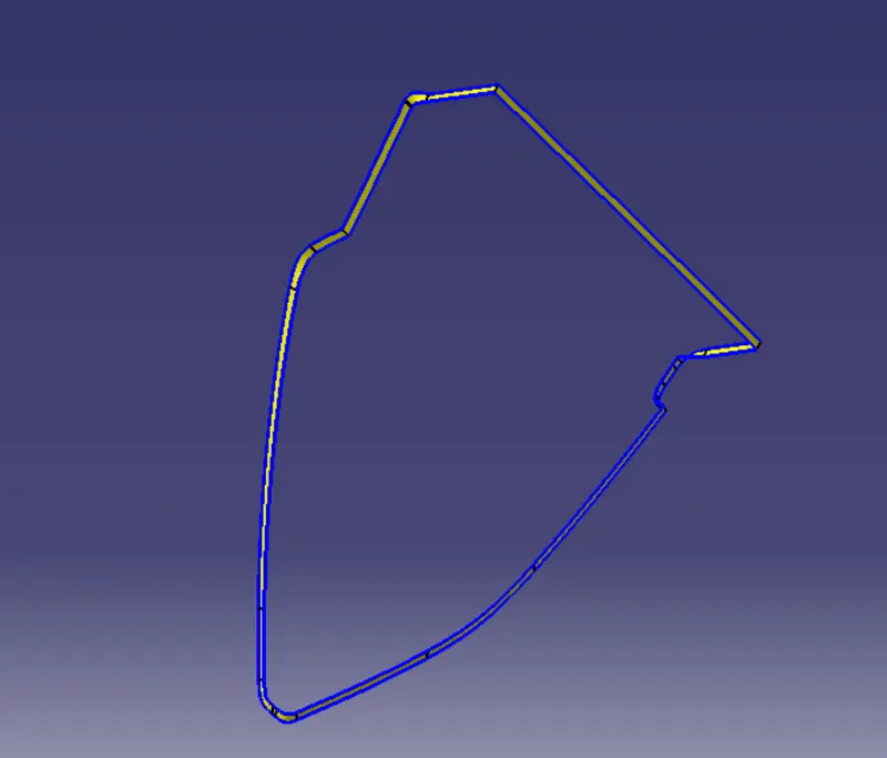
JOIN A & C SURFACE
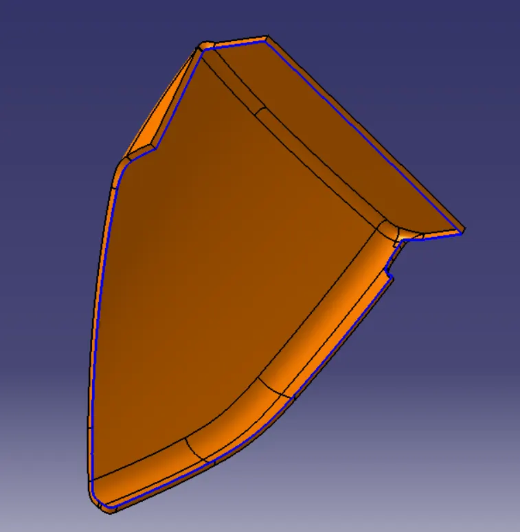
FINAL TRIM
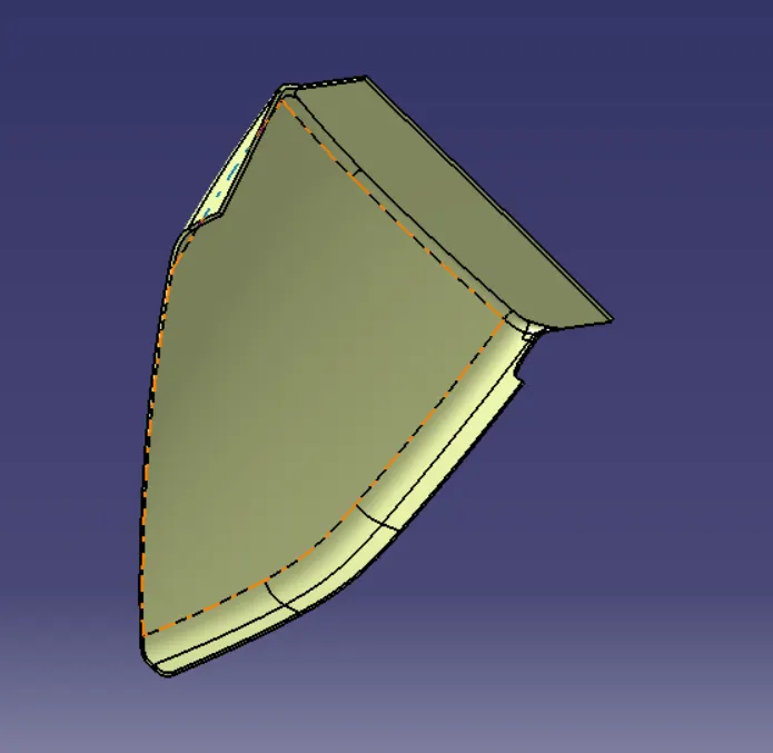
FINAL CLOSED SURFACE OF UPPER MAP POCKET
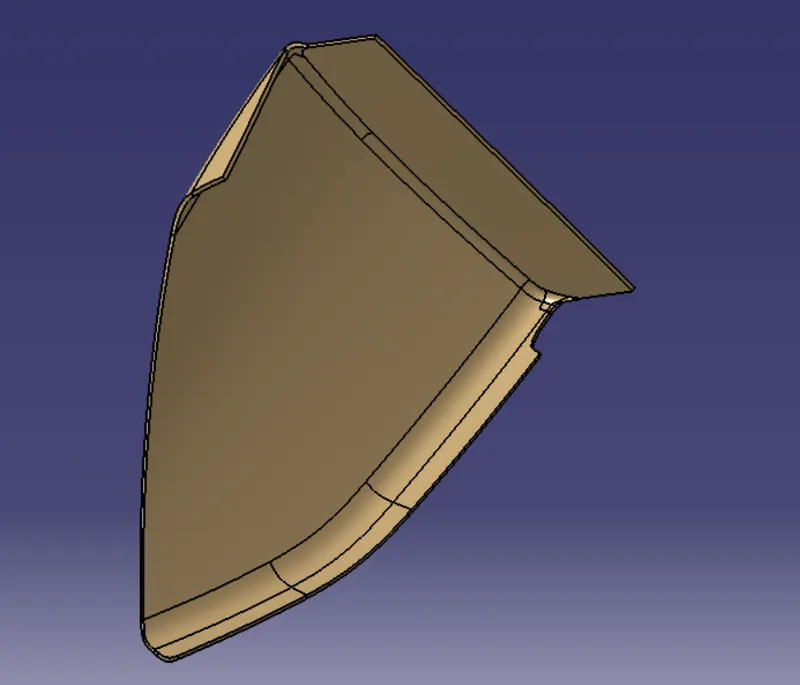
DRAFT ANALYSIS OF CLASS A SURFACE
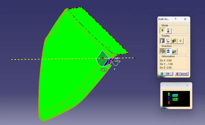
DRAFT ANALYSIS OF FINAL CLOSED UPPER MAP POCKET
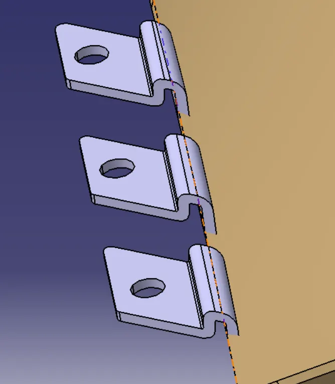
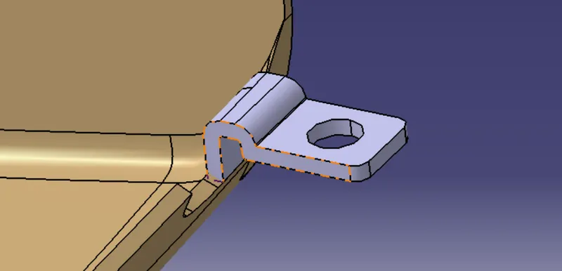
CREATION OF B-SIDE FEATURES
FLANGES- The same process just following the master section and following the design consideration.
Final Map Pocket Plastic Body
Final draft Analysis of Upper Map Pocket with B-Side Features
4. LOWER MAP POCKET / WATER BOTTLE HOLDER
So the steps are the same for this also first create a tooling axis then offset the Class A surface by 2.5mm so that we can get the Class B surface. After creating the Class B surface we work on the Creation of the Class C surface using the sweep command at an angle of 3 degrees outwards with respect to tooling direction. In some areas, the 90-degree sweep was applied.
CLASS A SURFACE
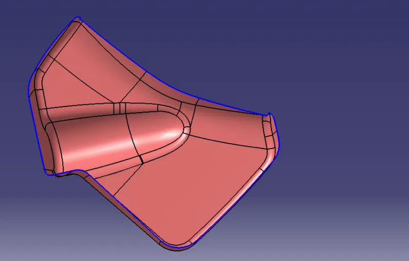
TOOLING AXIS
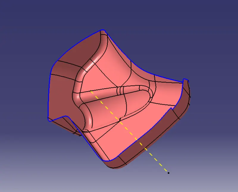
CLASS B SURFACE
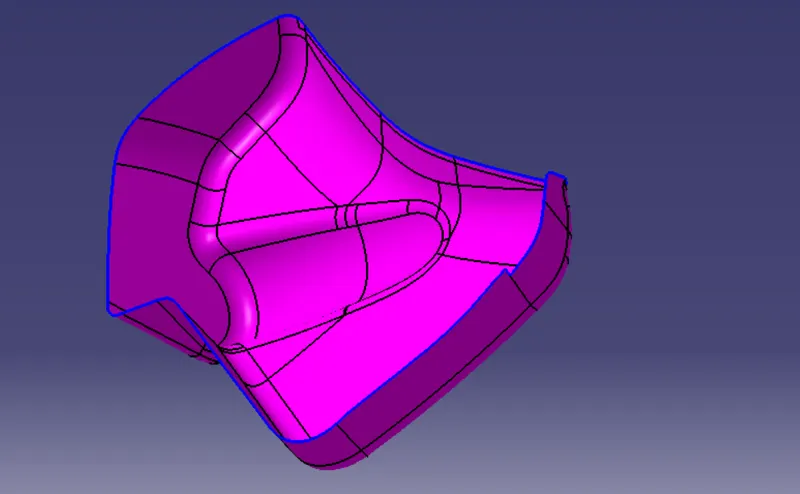
CLASS C SURFACE
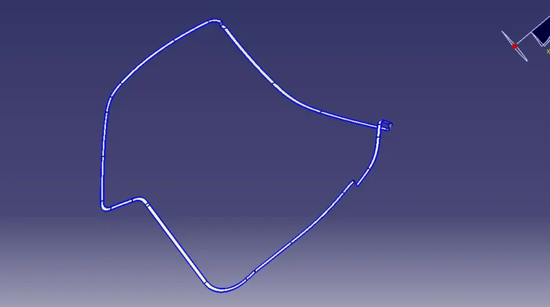
JOIN A & C SURACE
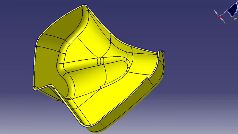
FINAL SURFACE
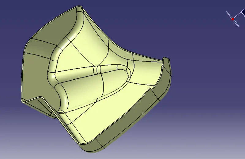
CLOSED WATER BOTTLE BODY
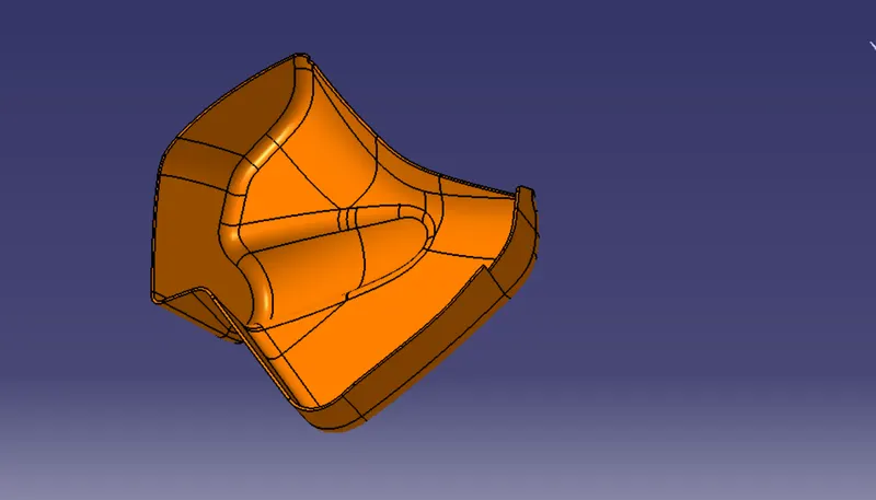
DRAFT ANALYSIS OF CLASS A SURFACE
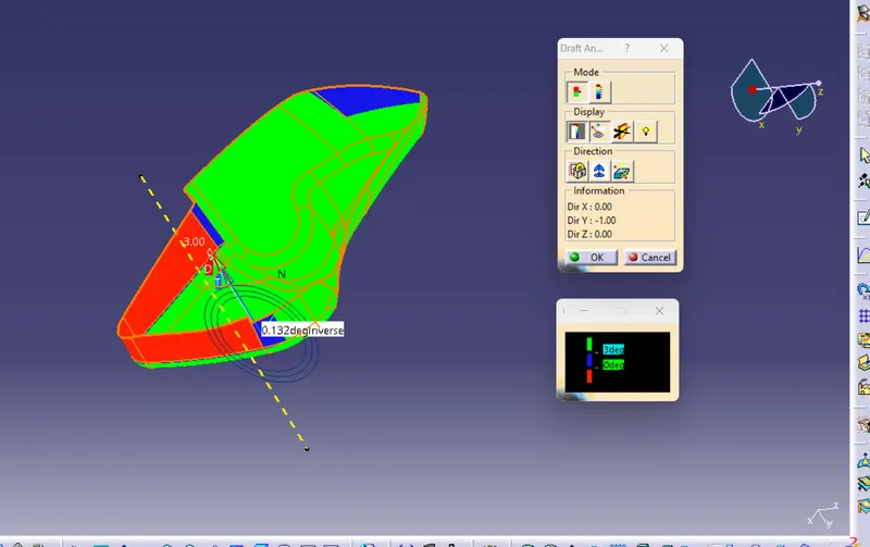
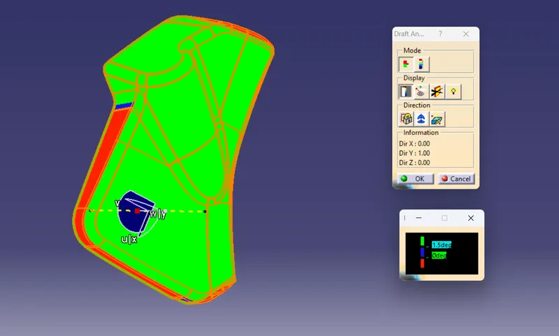
DRAFT ANALYSIS OF FINAL CLOSED WATER BOTTLE BODY
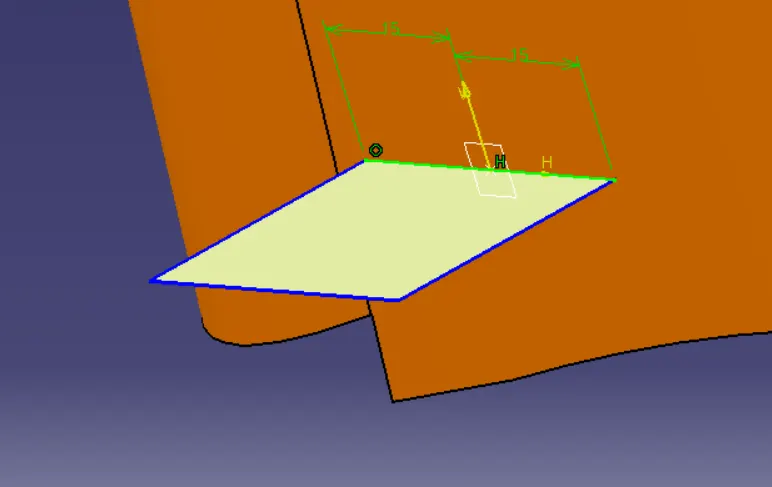
CREATION OF FLANGES
- First create a point over the surface then make a plane over it so that we can create a sketch.
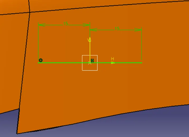
- After this, we use extrude command and thicken it with 2.5mm.
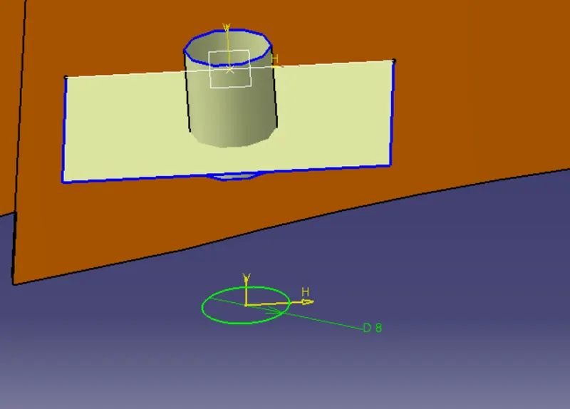
- Make a hole over the flange
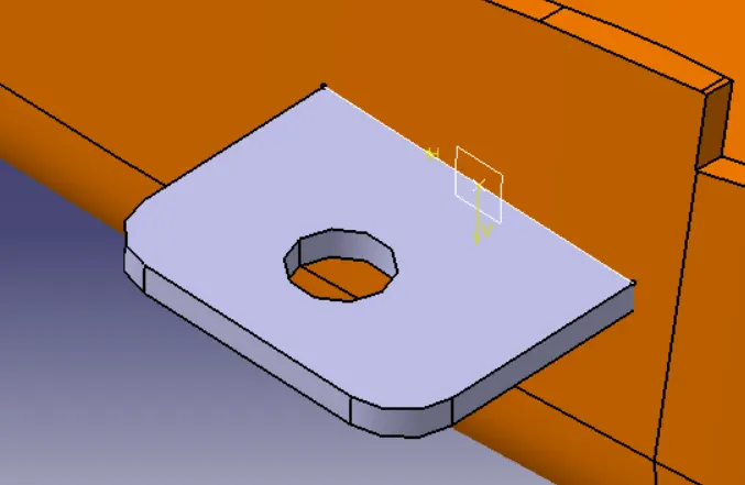
- The final flange is shown below:
Similarly creating 5 more flanges as requirement:
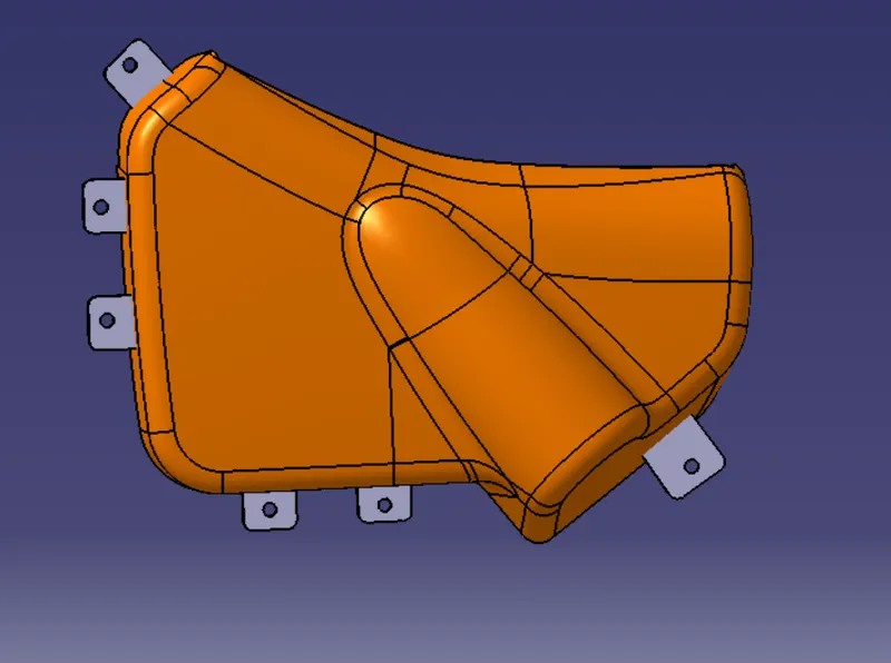
DRAFT ANALYSIS WITH B-SIDE FEATURES
CREATION OF PARTING LINE
Parting line: It is the dividing line that splits the core and cavity halves of a molded part.
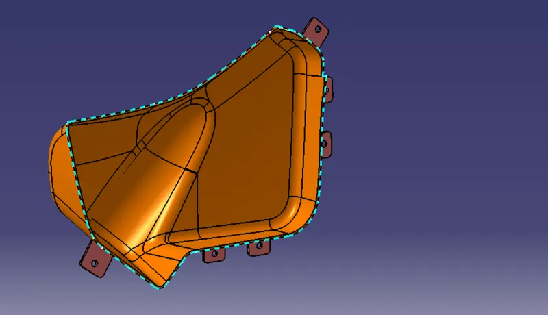
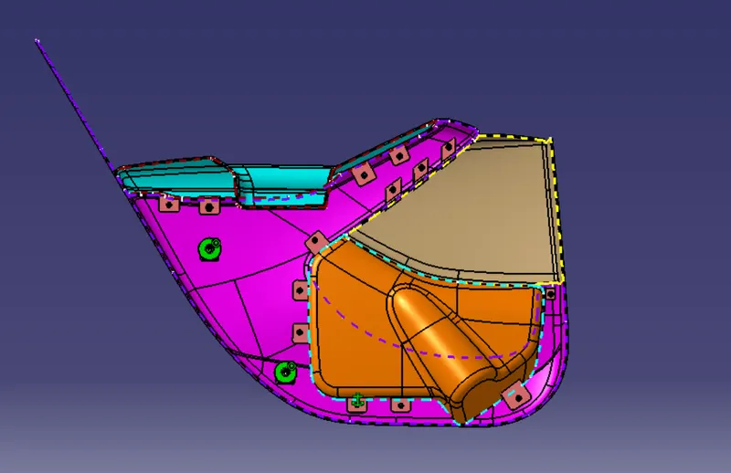
Intersect between B surface and class A-C join gives the parting line.
1. PARTING LINE OF MAP POCKET
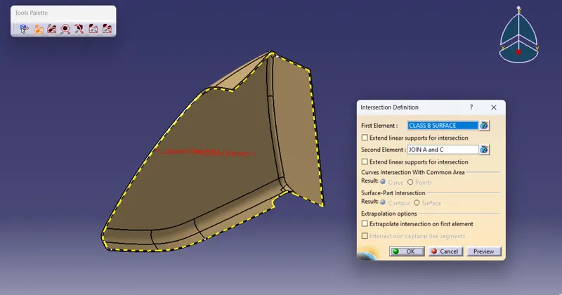
2. PARTING LINE OF ARMREST
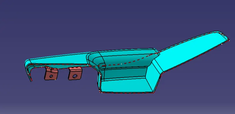
3. PARTING LINE OF LOWER SUBSTRATE
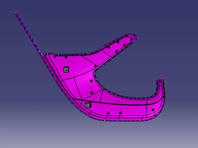
4. PARTING LINE OF WATER BOTTLE BODY
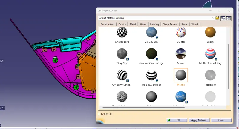
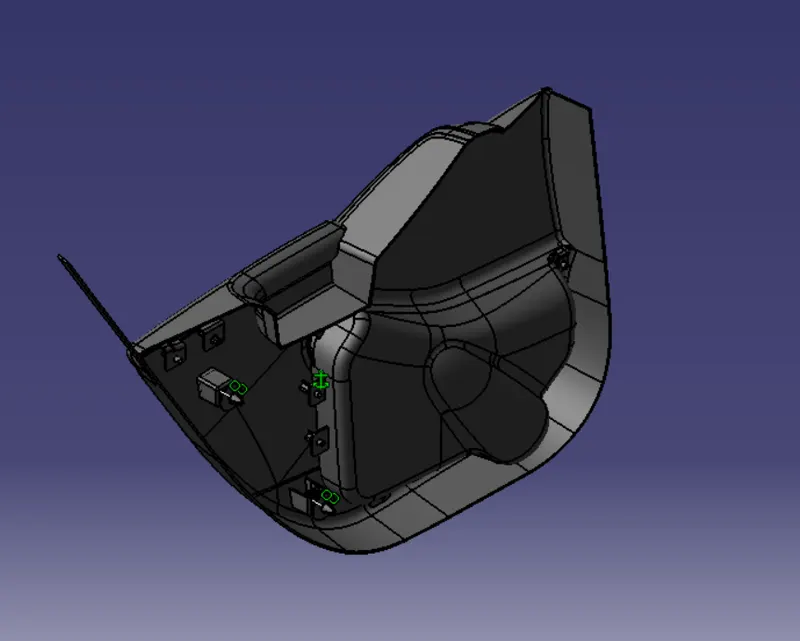
APPLY PLASTIC MATERIAL OVER THE DOOR TRIM
From the Assembly workbench click the command named APPLY MATERIAL and select plastic as a material.
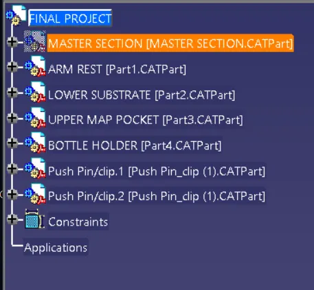
Tree structure: