Week 11 - Final project
AUTOMOTIVE PLASTIC DESIGN
' DESIGN & ANALYSIS OF SIDE DOOR TRIM PANEL' ( FINAL PROJECT)
Stages of the Product life cycle of the automotive industry:
Launching of any product whether its automotive ,household appliances ,medical devices etc involves different stages of product life cycle before launching it actually in the market . As we are talking about product life cycle in automotive industry it has majorly 10 stages they are as follows:
1) Sketch Concept: Imagination is the key concept of sketching,Automotive designers uses free hand sketching on papers as well as in different softwares available today such as Alias,Photoshop etc for generating new designs.
2) Class A Styling: It is the digital creation of body surface in software which looks aesthetically good and can be seen, Instrument panel, door panels ,bumpers etc are examples of class A surface creation.
3) Feasibility check : Feasibility check can be validated by two concepts , Most of the OEM using same components on different vehicles which is not visible to human as it is hidden by some aesthetic parts for an example let us consider new rim design for wheel although company may be offering new rim design with new designed spokes or alloys but the hub where the wheel is mounted and the hydraulic disc which is being used there remains of the same size and design only the rim which is visible to us has design changes so before manufacturing a new product feasibility are checked like this that whether it will be feasible with other mating parts . Secondly suppose a totally new design component is decided for launch so during the design validation its manufacturing feasibility is also checked that whether the sources or machine available with us will be able to manufacture the requied product or not . I was working in NPD and marketing department in a spring manufacturing company there after we recieve a RFQ for a new product we used to match the available thickness of spring that our cnc is able to produce and match it with the requirement of the customer and then contract was signed.
(4) Concept validation: During this face visibility and other safety checks are made suppose during a crash at a certain speed what all impacts the components can have and how far the human be safe all these things are valiated during this phase.
(5) New Product Design : The computer aided design for the part will be made in the cad software and the drafting of the component with all dimensions will be done .
(6) Development : During this phase the design team and manufacturing team work together and tools are decided for manufacturing of the product.
(7) Proto Built : During this phase usually in automotive industry clay models are prepared and product is showcased finally to all the design and other team members.
(8) Design validation : After the proto is built and finalized the design is then locked and no further changes are made in the design .
(9) Pilot Production : In this phase the product is launched in few numbers and is tested in all environment conditions and master records are prepared in form of charts stating the all test with the duration . In my experience while i was in the spring manufacturing company they used to test on spring one was life cycle test and other was corrosion test once these phases test passed the product was ready for mass production.
(10) Mass Production : This is the final phase of launching the product in which mass production is done as per requirement and the product is send to delivery partners for sale from vendors or Oem's .
New Product design is carried out from the Class A surface provided by the styler who uses softwares like Autodesk Alias and then Class B & Class C surface is developed to create a solid body out of it using softwares like CATIA, NX CAD, etc taking all the parameters into consideration specially the draft angle to make it manufacturable in injection molding process. Plastic components usually have 3° of Draft but 0.5 degrees can also be given to some engineering features like Dog house , ribs etc.
Method to develop plastic component:
- Creation of Tooling Axis
- Creation of Class B Surface
- Creation of Class C Surface
- Creation of Closed Body
- Creation & Attachment of B side Engineering features ( Dog House, Ribs, Screw Boss , Heat Stakes etc)
- Draft Analysis on whole component and its attachments
Main Components of Door
Although Car door is one of the complex component as it is made of sheet metal and plastic which also have electrical and mechanical work components
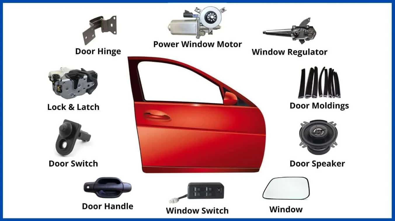
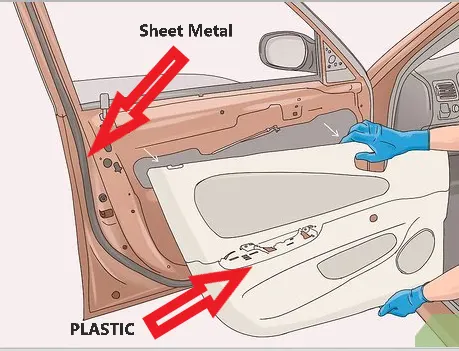
As I am designing Interior Door panel it consist of some limited components like
- Arm Rest
- Map Pocket
- Bottle Holder
- Lower Substrate
- Uper Substrate ( Not Provided in this project)
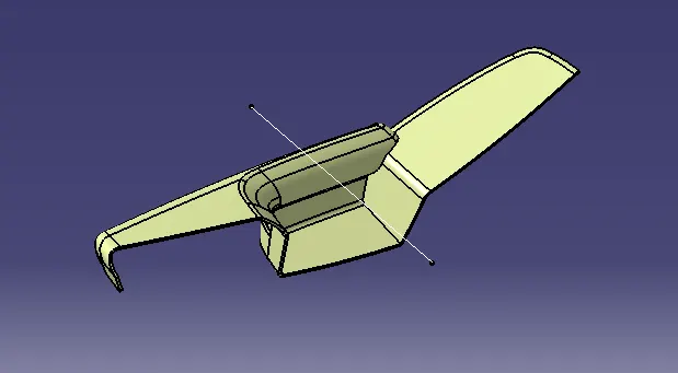
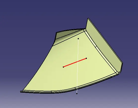
ARM REST Map Pocket
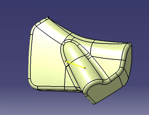
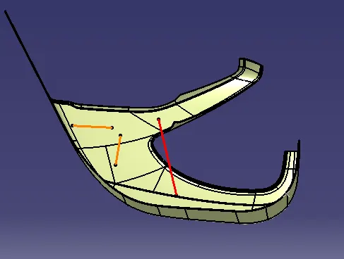
Bottle Holder Lower Substrate
Design Methodology:
Input:
Class A surface: It is one of the most important input in automobile industry specially in plastic design and is also one of the stages of design life cycle usually class A surfaces are created in Autodesk Alias for sketching concept modelling and visualization and then New product development in cad software is carried out. Class A is an aesthetic surface developed by a styler.
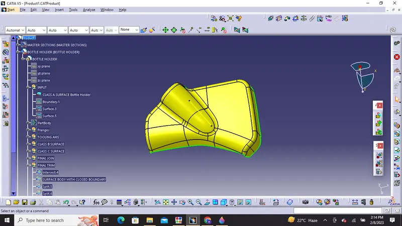
Bottle Holder
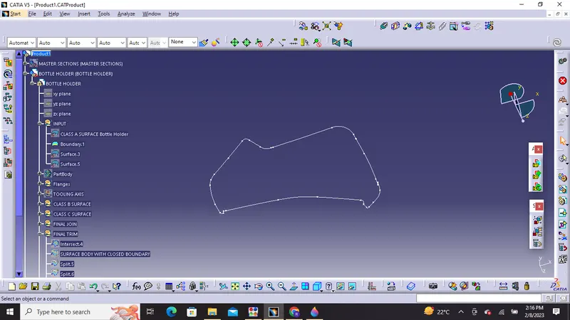
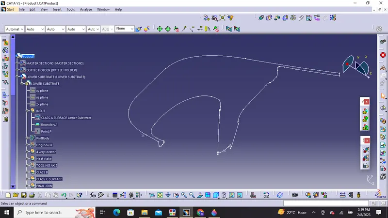
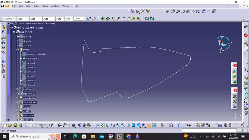
we will check the class A surface by putting boundary command on it and check for any irregularities so as to ensure that class A surface given is of good quality .
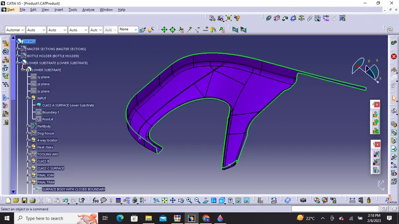
Lower substrate
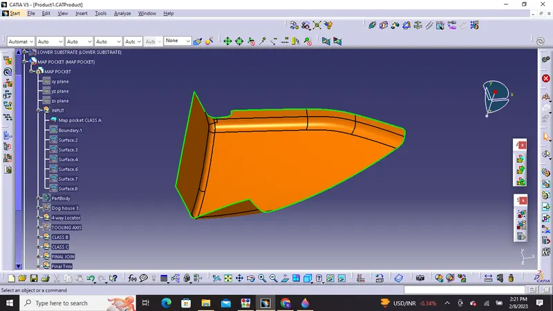
Map Pocket
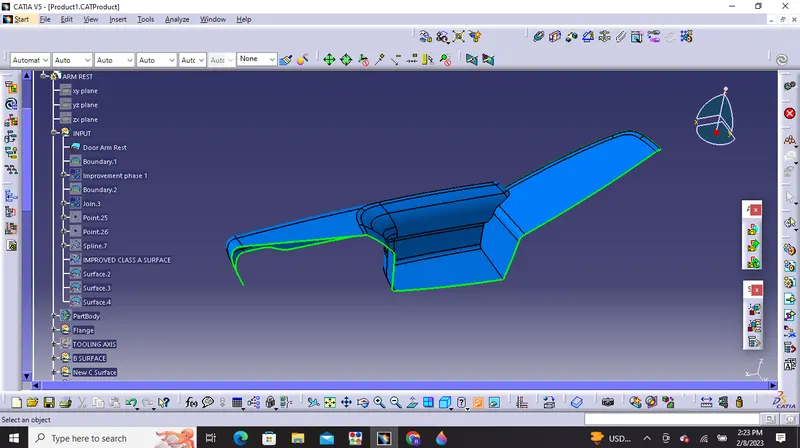
ARM REST
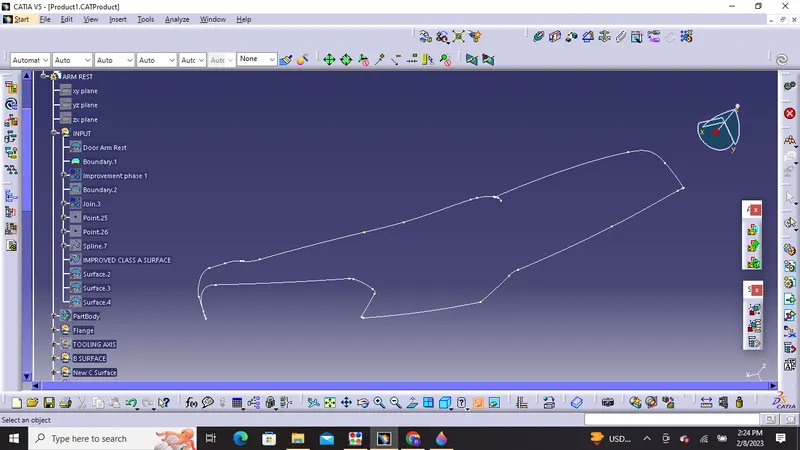
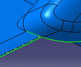
The Class A surface of Arm rest was not okay and there were some broken boundaries and patches or gaps in between which we have to improve and inform it to the styling team .
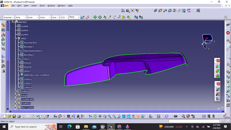
Improved Class A surface of Arm Rest
Class B Surface: B surface is the surface which gives us thickness from the class A surface, Class B is the engineering surface as all the engineering features like ribs ,boss etc are made on this surface.
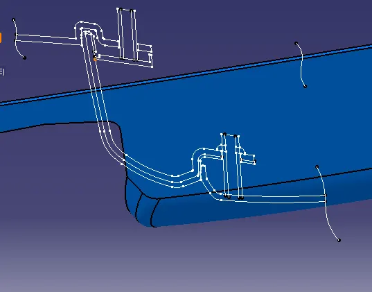
With Master section we can measure the thickness of the components to make sure how much we have to offset or provide thickness.
1) Bottle Holder
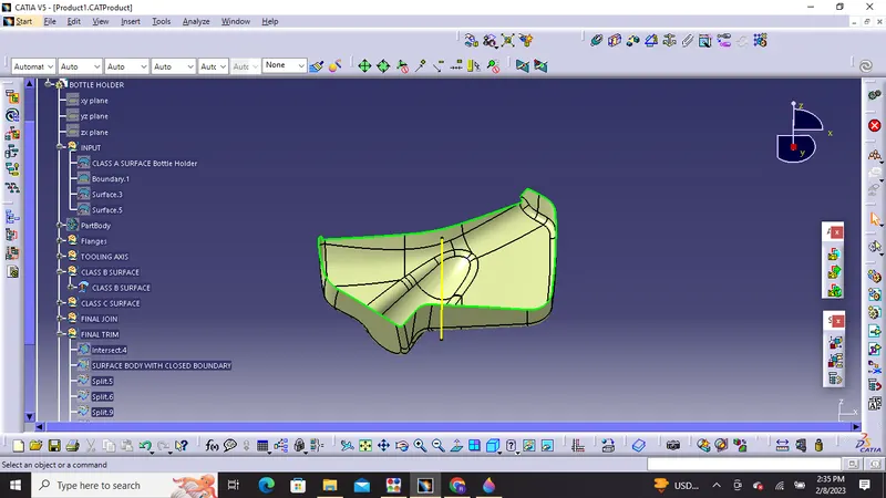
Class B Surface of Bottle Holder
2) Lower substrate
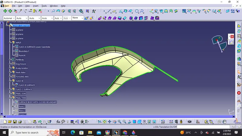
Class B Surface of Lower Substrate
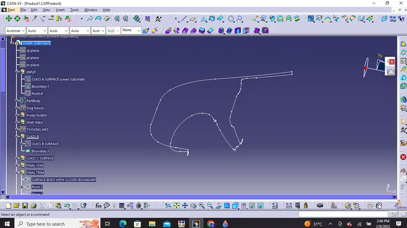
3) Map Pocket
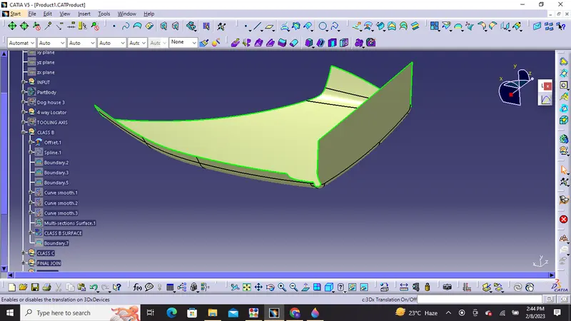
Map Pocket
An open patch at the corner can be seen after offset so we need to close that patch , I have used spline and multisection command to close that patch .
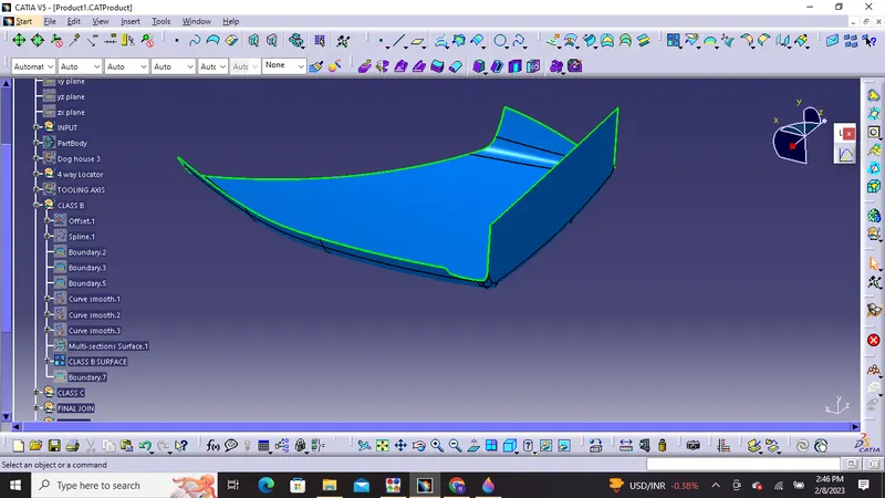
Class B Surface Map Pocket
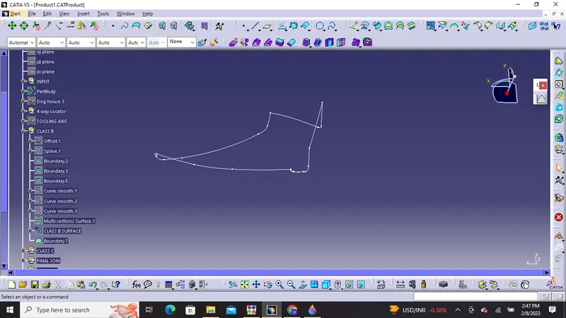
4) Arm Rest
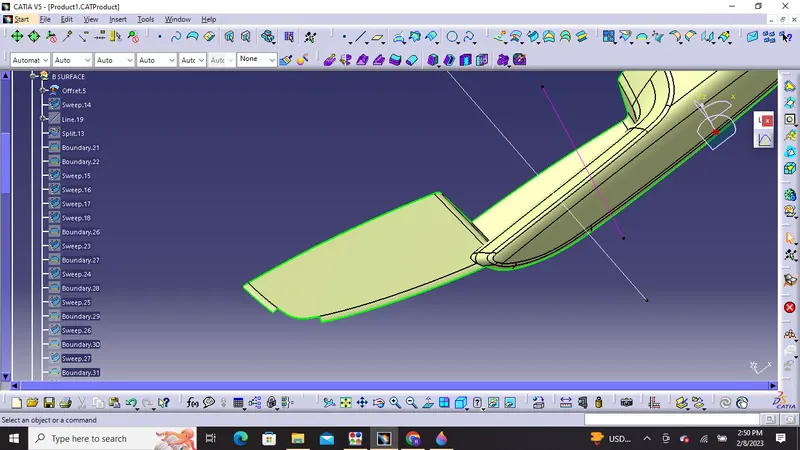
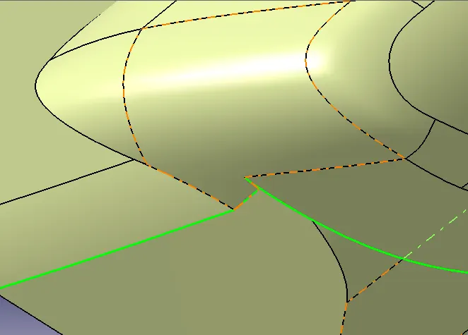
Arm Rest
After offset Arm rest had some patches and uneven boundaries
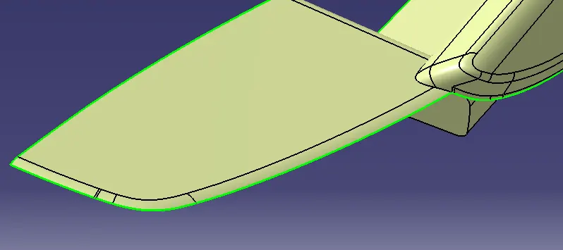
With the help of commands like Sweep , Multisections, extrapolation, split and trims all the uneven patches and boundaries were closed
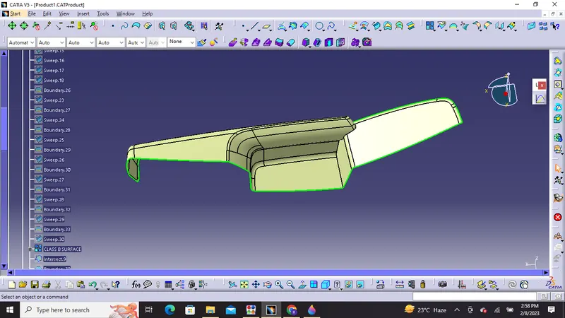
Class B Surface Arm Rest
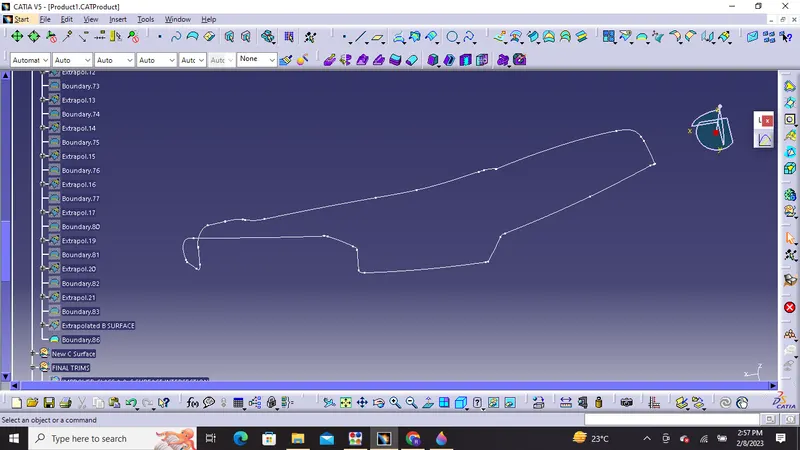
Class B Surface with no patches or discontinued body
Class C Surface : C surface is the surface which connects A and B along the tooling direction and is called Class C surface. We can make class C surface using extract,sweep, trims,extrapolate etc.
1) Bottle Holder
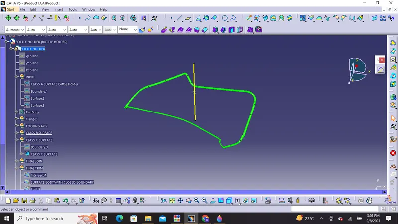
2) Lower Substrate
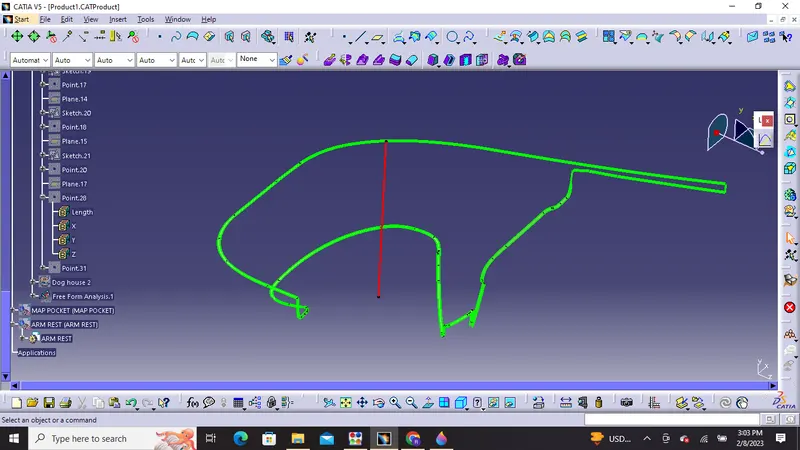
3) Map Pocket
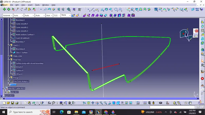
4) Arm Rest
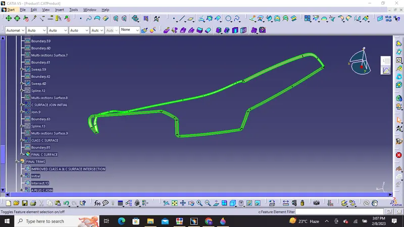
Arm Rest C Surface creation was quite challenging as it has more curvy areas on the corner , Commands like swept with reference to surface , Multisections, extrapolate, split and trims were used to create the Class C surface
Final Trims : Class A and Class C surfaces are joined and are trimmed against extrapolated B surface giving us the final surface body with closed boundry.
1) Bottle Holder
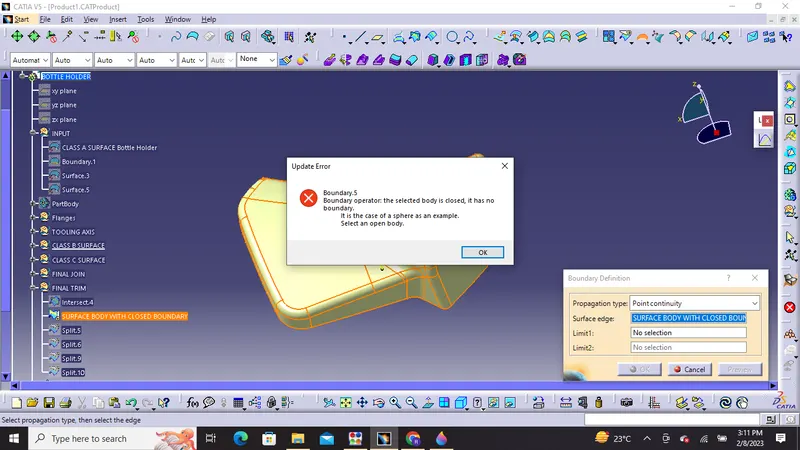
Surface boundary with closed boundary without engineering features
2) Lower Substrate
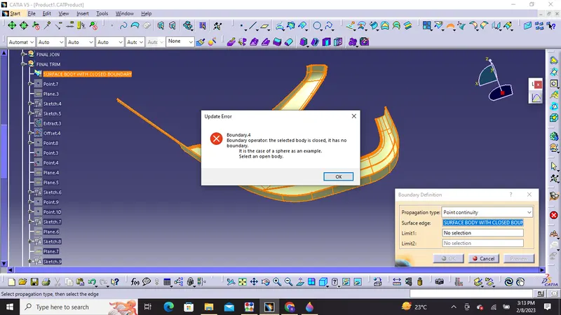
Surface boundary with closed boundary without engineering features
3) Map Pocket
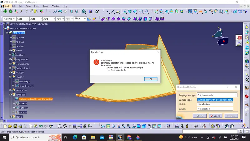
Surface boundary with closed boundary without engineering features
4) Arm Rest
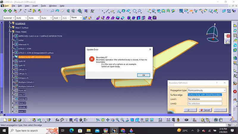
Surface boundary with closed boundary without engineering features
Tooling Axis:
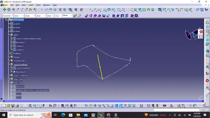
we can extract a surface from class A and create a point in the middle of that surface by using point command and create a line normal to that surface at that point through the y axis and we will perform draft analysis to check whether the created tooling axis is in the correct position or not ,If in the draft analysis both the surface sides are in green color our position is correct.
or we can also follow bisection method through intersection.We can make tooling axis by center point on the model and using intersection we can create bisecting lines and bisecting line will bisect the two lines if they are perpendicular and will show some error if they are parallel this will decide that whether the surface is toolable or not and then perform draft analysis on it as we performed on previous projects.
But for Tooling axis creation in complex and large parts like door trim ,bumpers,etc we can also draw tooling axis in the centre of gravity point using inertia method as The centre of gravity is a point in an object where the distribution of weight is equal in all directions and this point will be suitable for the direction of extraction of component very easily.
Steps for inertia method are as follows:
1) We will click on measure inertia button which is beside measure item .
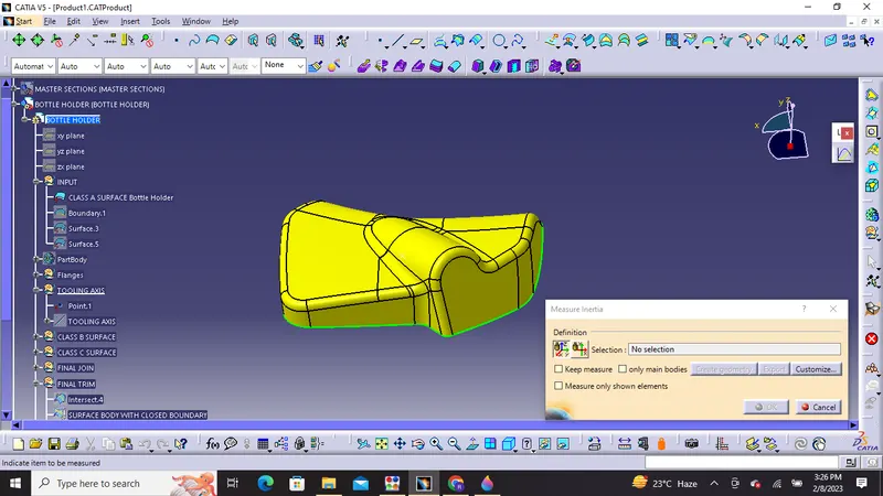
2) After selecting Class A surface we will next click on create geometry
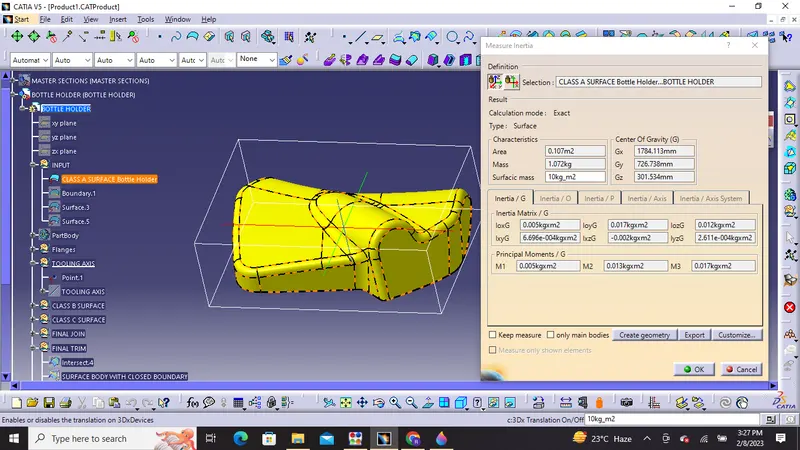
3) Furthermore we will click on non associative geometry and select centre of gravity and press ok
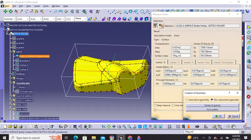
4) The inertia point will be created.We will select a line and select point and direction in which inertia point and Y direction is choosed for final creation of tooling axis
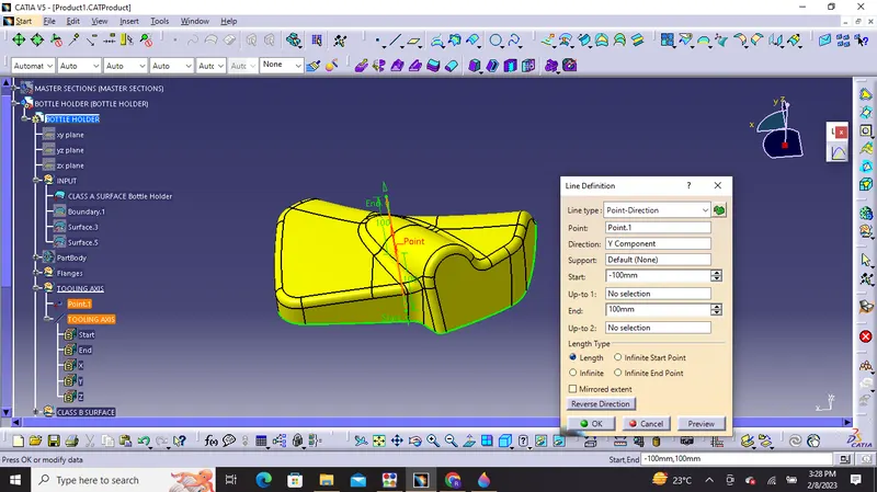
Tooling Axis & Draft Analysis on Class A surface :
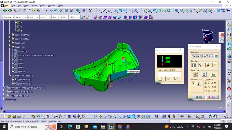
Some areas in class A surface is showing zero degree inverse
2) Lower Substrate
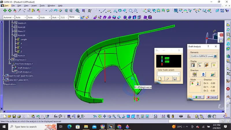
Tooling axis for lower substrate clearing with 3 degree draft
3) Map Pocket
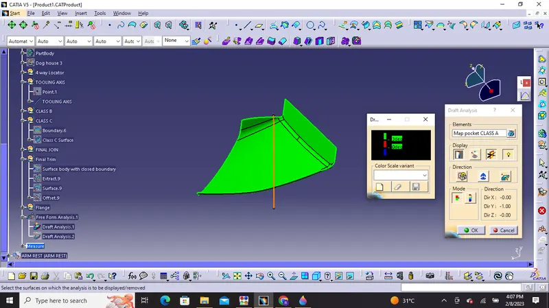
Tooling Axis for Map pocket clearing 3 degree draft
4) Arm Rest
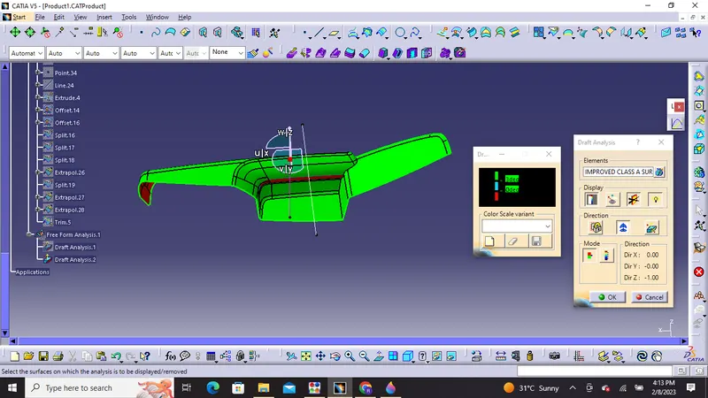
As some of the regions in arm rest is not clearing we have to make a side core axis for that
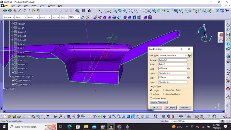
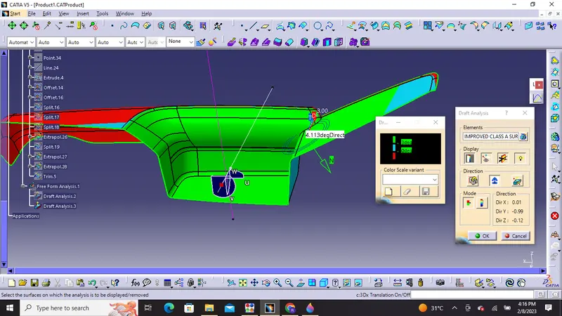
With this the center part is now getting cleared
Draft Analysis:
Draft is the angle in which the part is tapered to allow it to release from the mold properly and as the part is cooled it has a tendency to shrink towards the core side of the mold due to this we need to add draft angles.Nominal draft angles is usually around 3 degrees and more than 3 degrees can also be manufactured like 5 degrees but it will unecessarily increase the costing of manufacturing and final product.
Procedure used for draft analysis in Catia cad software:
1) In display frame first we need to change it to material mode
2) Click on insert then analysis and select feature draft analysis
3) Then we will click on compass and and align it with tooling direction.
4) Then we will click on the lock symbol and then click on the surface of the part the colour will change
5) Different color codes are identified and there we can apply draft angle which will reflect us minimum draft angle in green color.
6) We can also have running point analysis on different regions of the part body for permissible draft angle
Draft Analysis on Final component with B Side features:
1) Bottle Holder
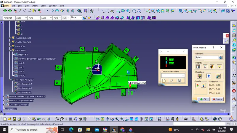
3 Degree of Draft
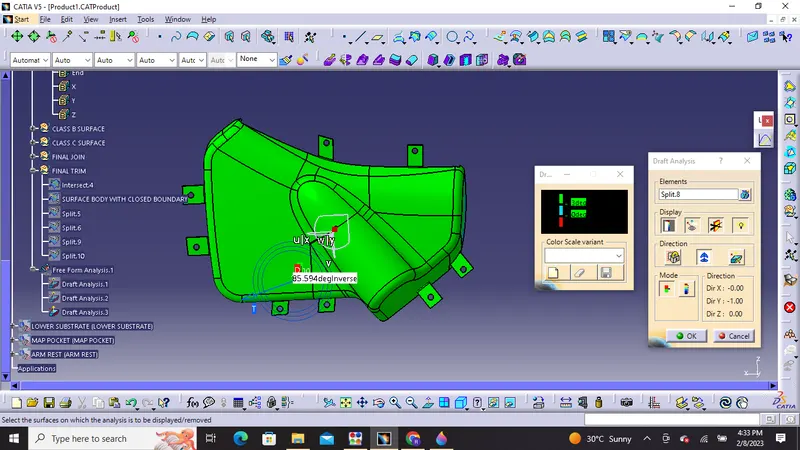
3 Degree of Draft
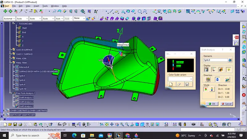
0.48 Degree of Draft Some side areas are having zero degree draft
2) Lower Substrate
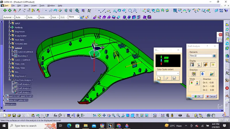
Surface body getting cleared at 3 degree of draft
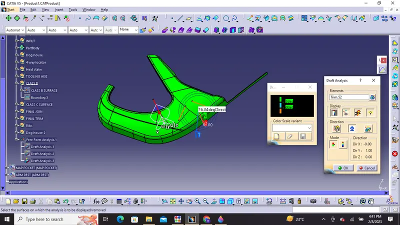
On inversing draft it is also clearing at 3 degrees
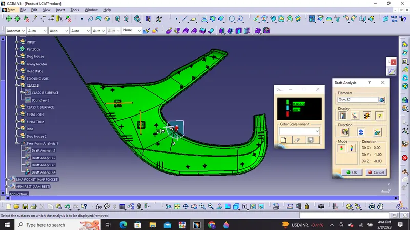
0.48 Degree of draft for B side feature
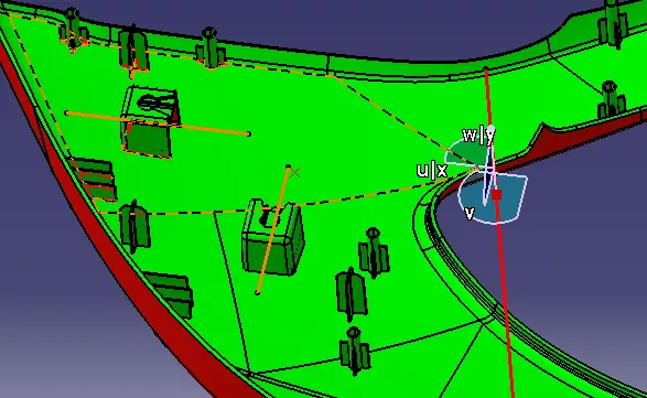
At 0.48 degree of draft all the B side feature is getting cleared
3) Map Pocket
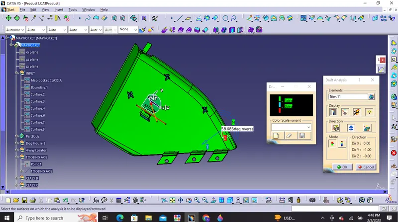
3 Degree Draft for surface body
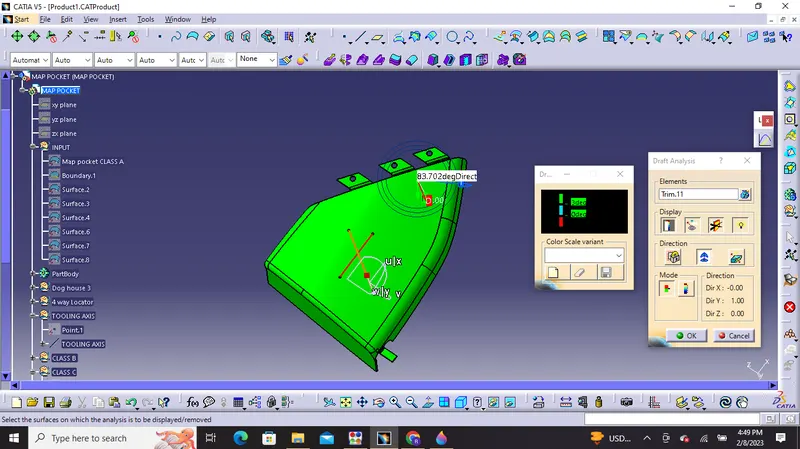
On inversing it also clears at 3 Degree draft
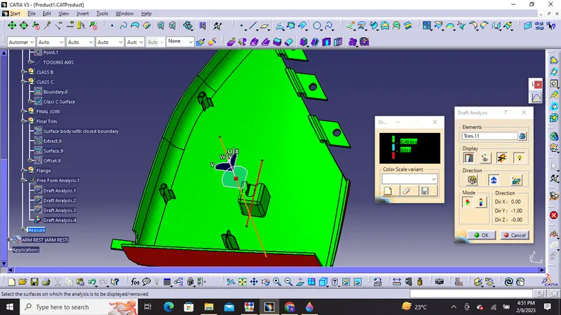
At 0.48 Degree all the B side feature is getting cleared
4) Arm Rest
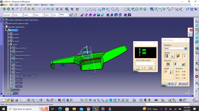
3 Degree of draft
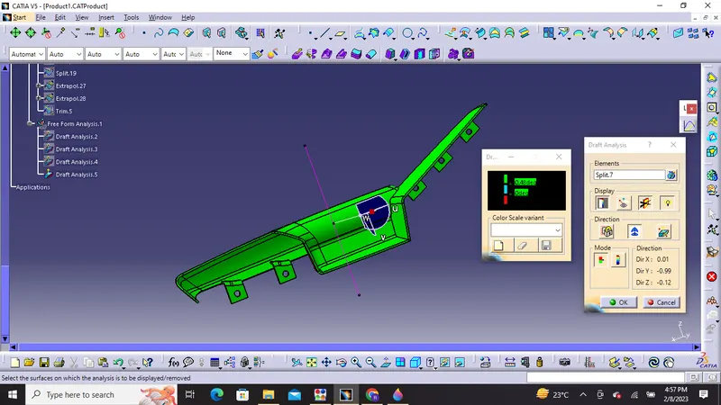
0.48 Degree of draft using side core axis for B side feature and center region
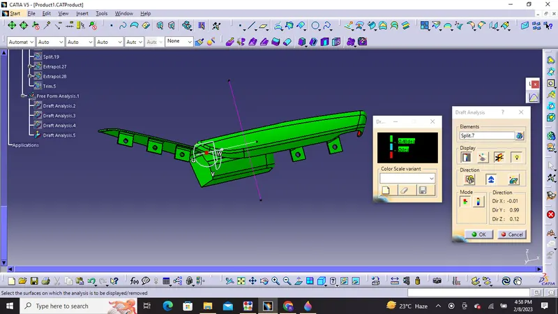
On inversing 0.48 Degree of draft using side core axis for B side feature and Back region
B SIDE ATTACHMENT FEATURES :
1) Locators & Heat stakes
Significance of 3-2-1 Principle: The 3-2-1 principle of a location six point location principle is used to constrain the movement of workpiece along the three axes XX,YY, and ZZ. Any part which has to be fixed during welding or during machining process has to be fixed. Every object is having 12 degrees of freedom.
By Degree of freedom we mean the capability of a body to move in twelve different directions six rotational and six axial. Engineering features like locators are used to follow this principle.
Locators are also divided into 4 way locators and 2 way locators . A 4 way locator mean we prevent movement at 2 axis (+X, -X, +y and -y) on the plane,generally we have cylindrical pin on the fixture and circular hole at workpiece part. On the other hand 2 way locator means we can prevent movement at 1 axis on the plane nad we generally have the cylindrical pin on the fixture and slot hole at work piece part.
Design procedure for 4 way locators :
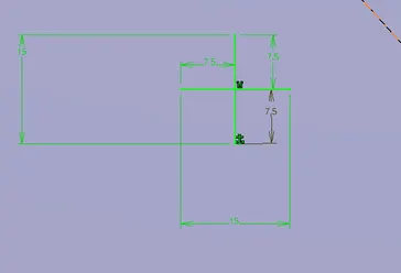
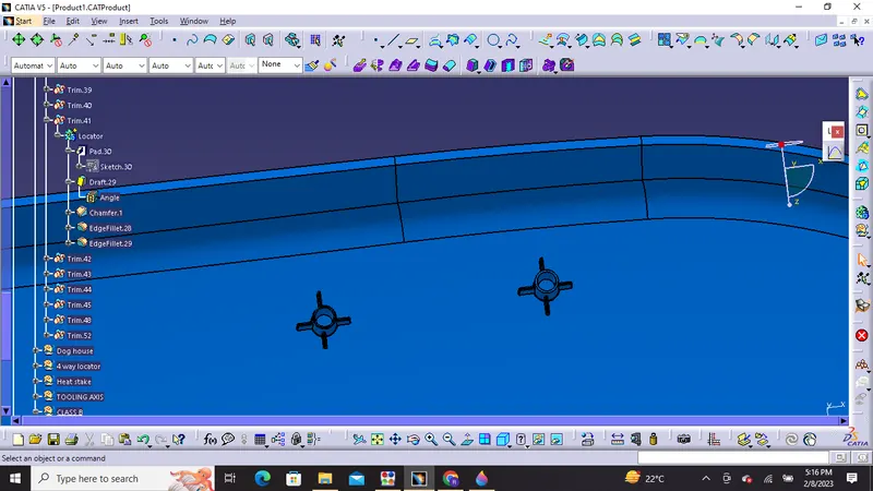
1) WE HAVE TO SKETCH using positioned sketch
2) We have to pad it along the tooling axis
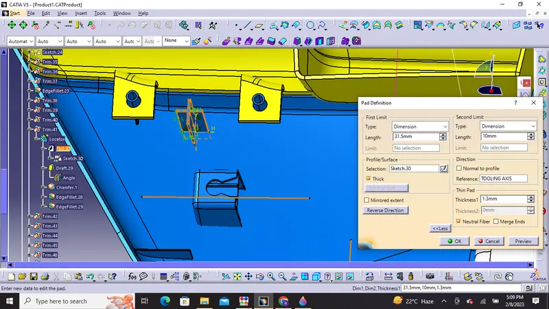
3) We have to apply Draft angle of 0.5 degrees in all the faces.
4) We have to apply a chamfer of 3*45 degrees on the to face for the penetration of the locators into the holes.
5) Edge fillets of 0.3 or 0.25 mm are given to all the edges.
Most important thing while giving draft is that we have to select it along the tooling axis.
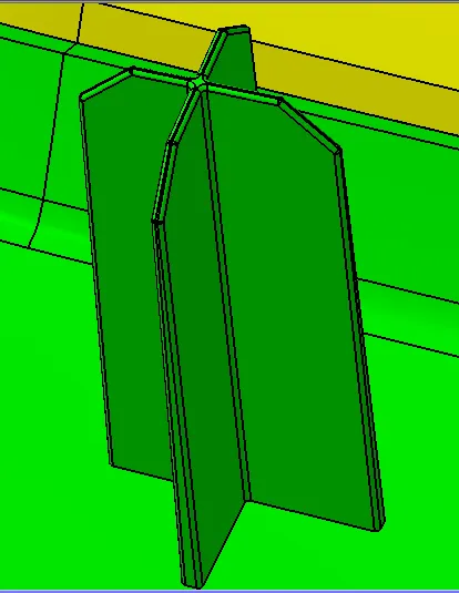
4 Way Locator with cleared draft
Heat stakes: Heat staking technology is quite simple in concept. Whenever two or more components need to be attached to one another, and at least one is made of a thermoplastic, a combination of heat and pressure can be used to reform the plastic to the many shapes or profiles to retain or join the parts together. It is also called thermal staking which is an assembly method that uses controlled melting and reforming of a plastic stud or boss to capture or lock another plastic or metal component of an assembly in place.
The plastic stud protudes through a hole in the component to be locked in place. The heated thermal tip contacts the top of the stud which melts and fills the volume of the tip cavity to produce a head , locking of the component in place.
Design procedure for Heat Stakes :
1) We have to use positioned sketch
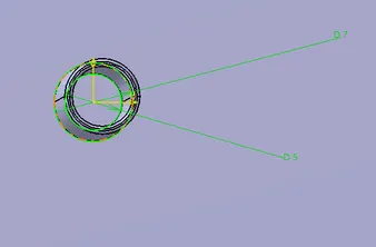
2) We have to pad it along the tooling axis but we have to make one thing for sure that the height of heat stakes should be lower than that of the 4 way and 2 way locators
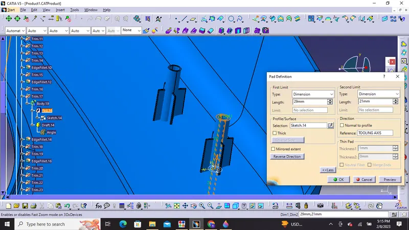
3) We have to provide a draft angle of 0.5 degrees on both walls of the heat stake.
4) The minimum gaps between each heat stakes should be of 40 to 60 mm .
We can also provide ribs on side of heat stakes for increasing its strength
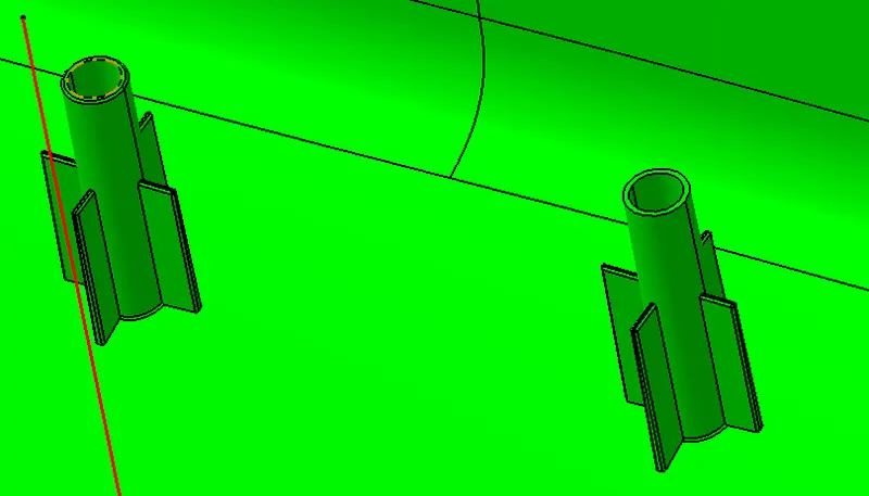
Heat Stakes
2) Ribs: They provide a means to economical stiffness and strength in molded parts wthout increasing overall thickness. They also facilitate some of the features like:
- Locating and arresting components of an assembly
- To provide alignment in mating parts
- It can also act as a stop or guides for mechanisms.
Proper rib design involves five main issues like:
- Thickness
- Height
- Quantity
- Location
- Manufacturability
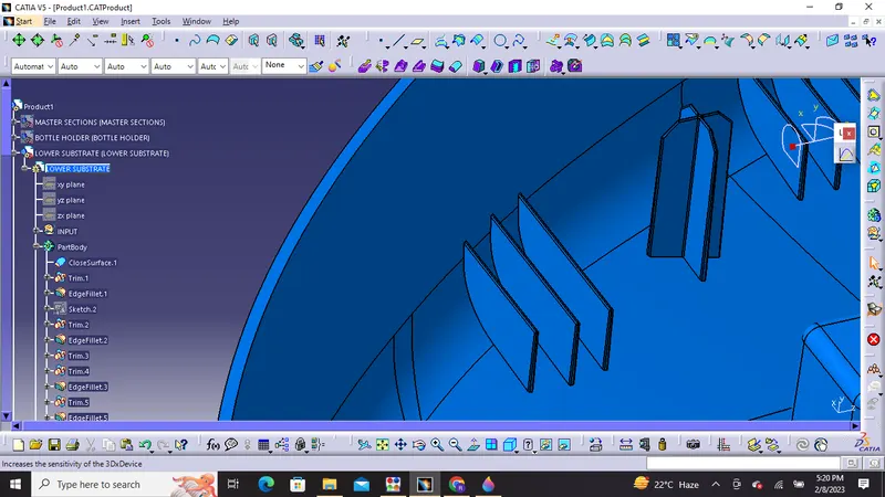
Calculations for Ribs :
1) Maximum thickness of ribs = 0.4 x thickness of component
In our Lower substrate the thickness is 2.5mm so max thickness of rib can be around 1 mm
2) Height of the ribs : It is 5 times the thickness of the component
In our Lower substrate the height of the rib is [5 x 2.5=12.5mm]
3) Draft: 0.5 Degress of draft should be given on the ribs
4) Rib Thickness at tip should be greater than or equal to (>0.75mm) our is 0.786mm
5) Edge fillet : 0.25mm on ribs face or edge
6) Rib root thickness should be be 1.4 times thickness of component and maximum of around 4.2mm
7) Spacing between ribs can be according to 3: 1 ratio height to width suppose height of rib is 12.5 and space between ribs is x which is equal to 3:1 ratio then 12.5/x = 3:1 which is equal to x=4.1mm. Although spacing can be altered as per requirement only thing is that it should be manufacturable.
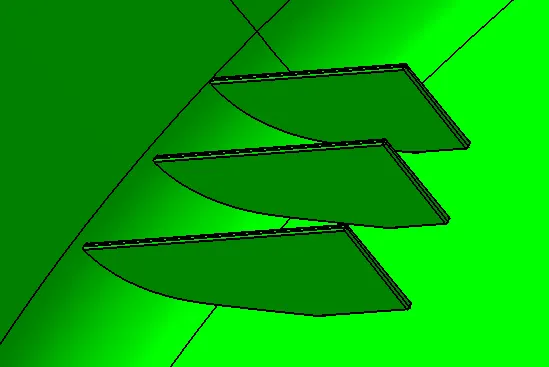
Ribs
3) Dog House:
Dog house is an engineering feature to avoid sink marks which is created on surface by screw boss or ribs on back of class A and also there will be length issues but with dog houses we can increase height of that area by giving cross section along B and can still have engineering feature on it.
Design Rule for Dog house are as follows:
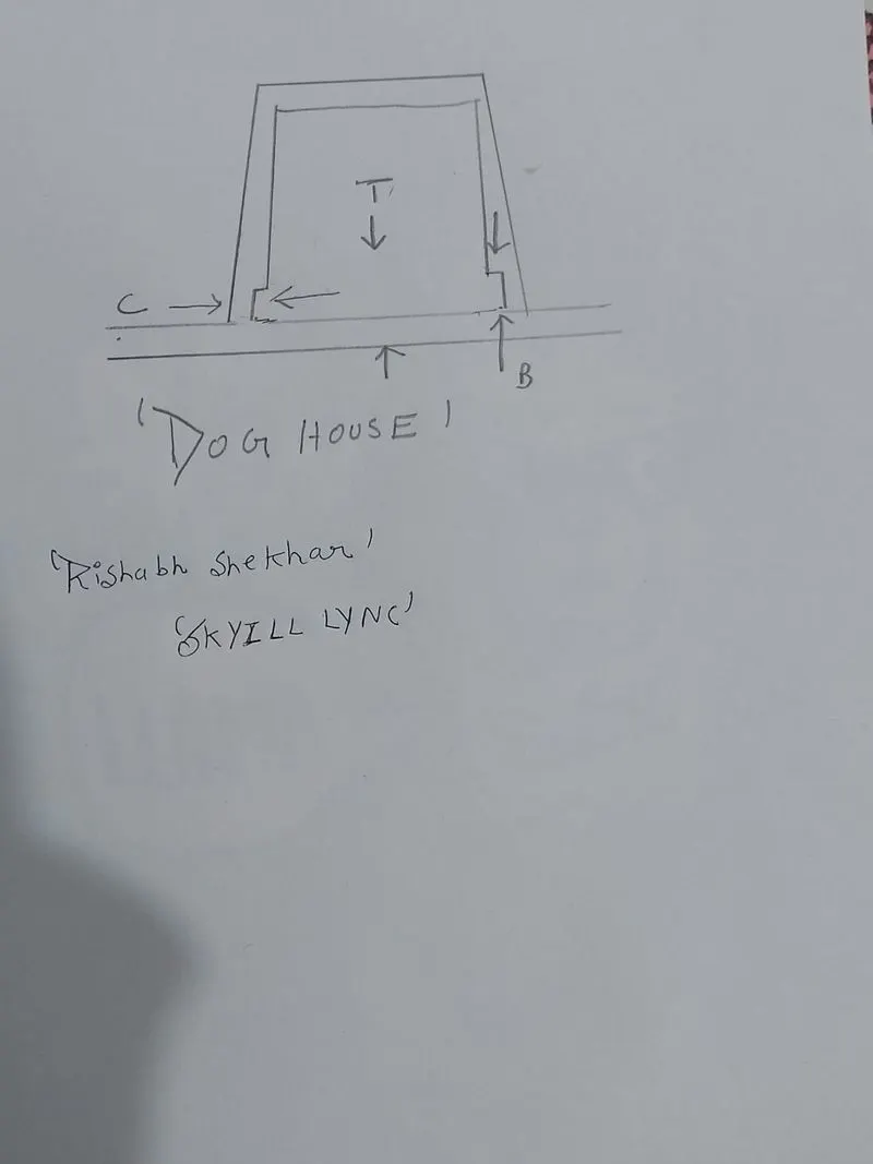
1) Dog house wall thickness at intersection of part wall (C) should be 40% or less than the main wall thickness.
Suppose the main wall thickness of the component is 2.5mm then 40% of it will be [0.4x 2.5= 1mm)
C is where the doghouse contacts the backside of the surface.
2) The height of the (B) should be between 3.0 to 6.0 mm in my design i considered it around 4 to 5 mm.
3) The minimum dog house width should be atleast 12mm due to molding feature.
4) Minimum draft for dog house is around 1.5degrees but if a slide is being considered this requirement can change to 3 degrees minimum.
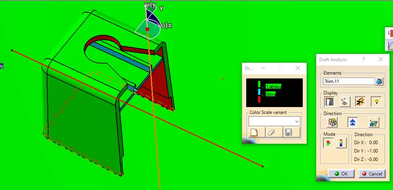
1.5 Degree of draft on outer body of dog house clearing at 1.48 Degree using main tooling axis
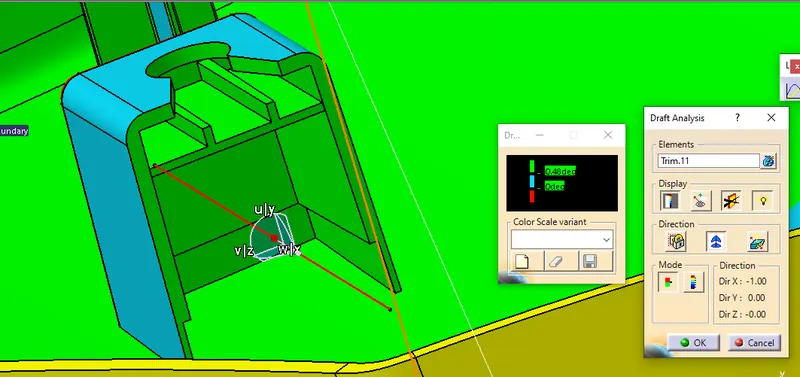
Inner areas of Dog house getting cleared with 0.48 degree of draft as 0.5 degree of draft is provided with respect to side core axis
One more attachment feature known as Flanges are made for attachment of heat stakes with respect to one body with another
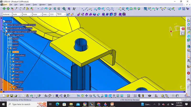
Flange
Master section was followed in the areas where attachment feature were to be made compulsory
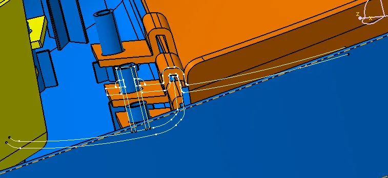
Pushpins: The pushpins are the attachment to the Dog Houses which helps to join with the other component features by locking it.
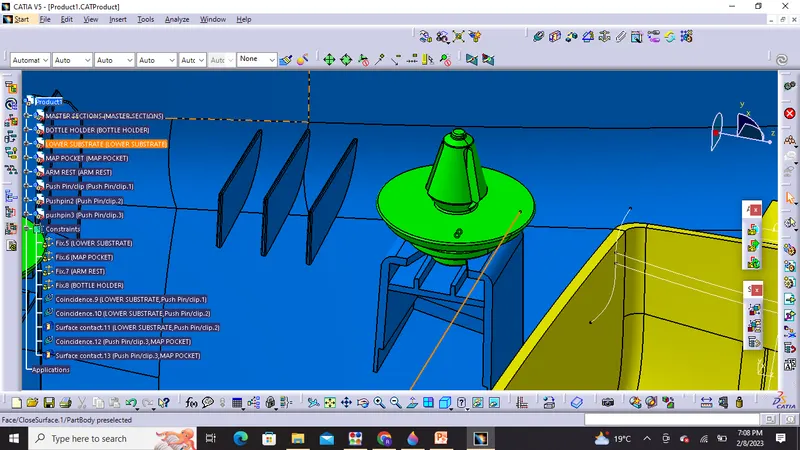
Pushpin
Assembly :
Assembly in any cad software can be followed by two approaches such as:
A) Bottom up Assembly : In this type of approach the parts are created individually in part workbench and then are assembled in assembly workbench with the help of geometrical constraints and other features. In this assembly project i followed bottom up assembly approach.
B) Top down Assembly : In this type of approach the parts are created inside the assembly workbench by starting the product file and then creation of individual parts is carried out and they can be opened separately in part workbench.
However we can also use both types of assembly combination at a same time if some parts are created while others can be created in assembly workbench.
I have used Top down Assembly procedure for these components
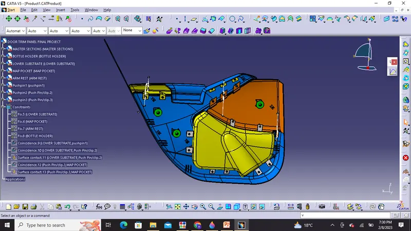
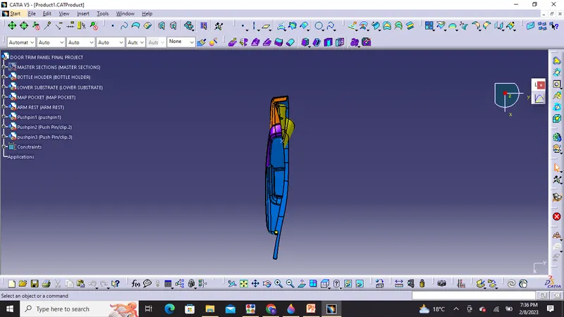
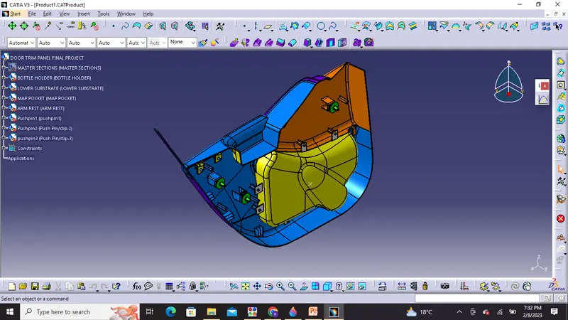
Tree Structure of Product
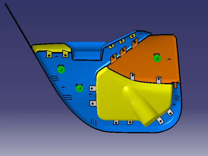
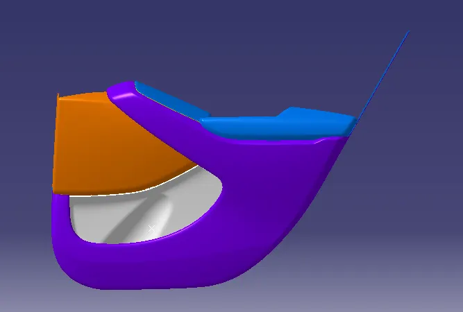
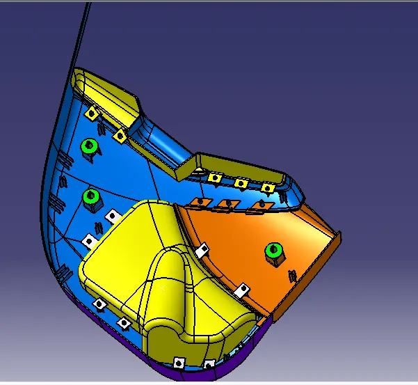
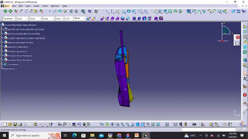
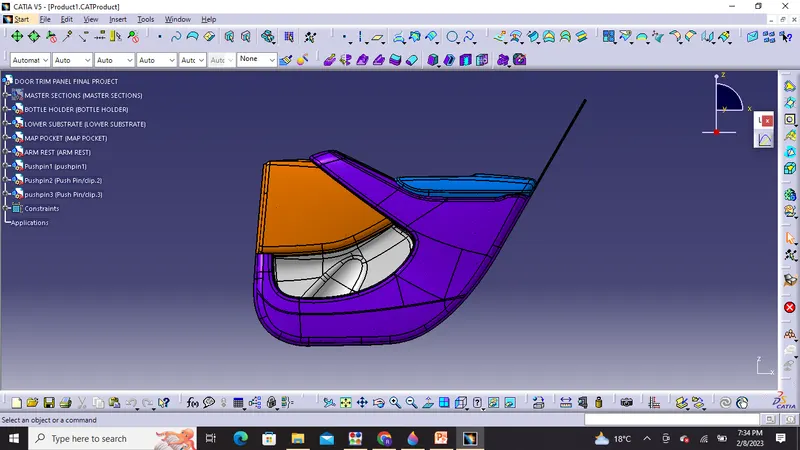
Different Views of the component after giving all assembly constraints
1) Isometric view
2) Front View
3) Side View
Left View
Right View
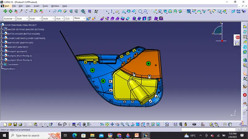
4) Top View