Week 11 - Final project
Development of a Door Trim panel
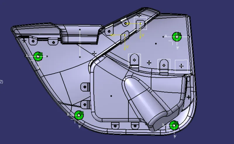
given INPUT
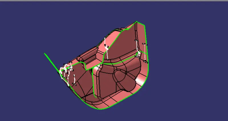
TREE STRUCTURE
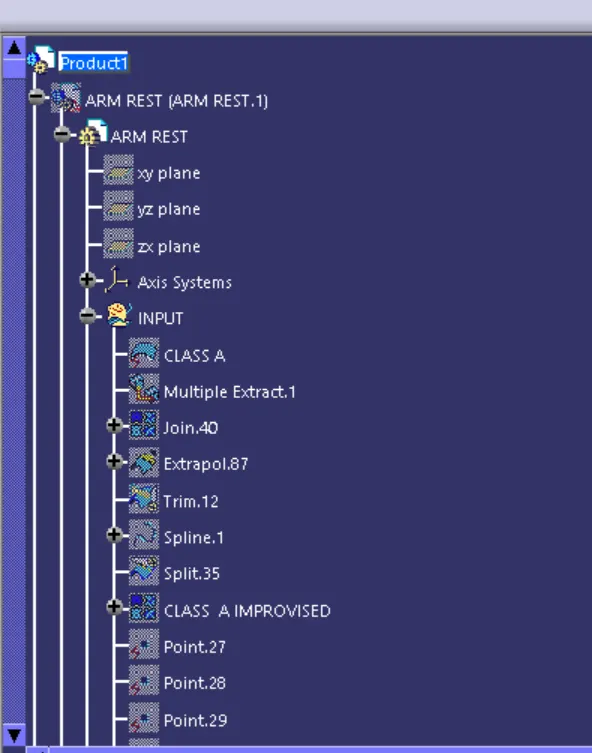
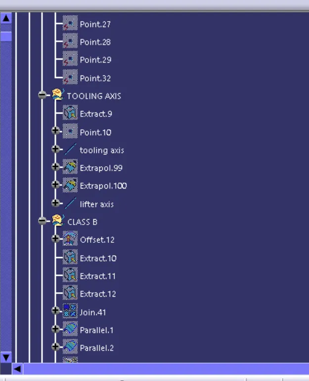
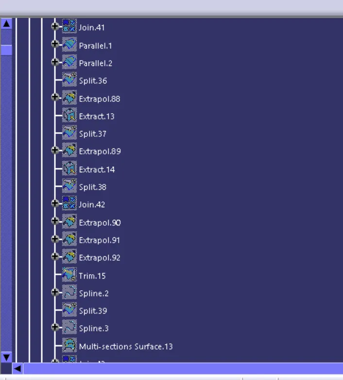
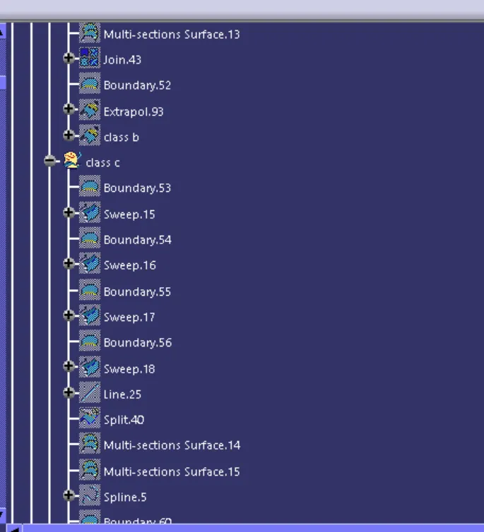
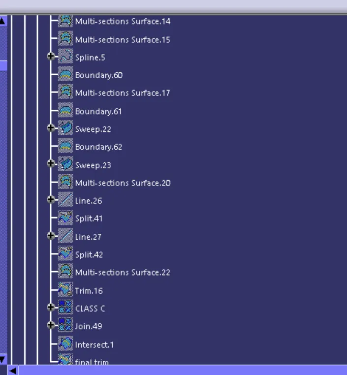
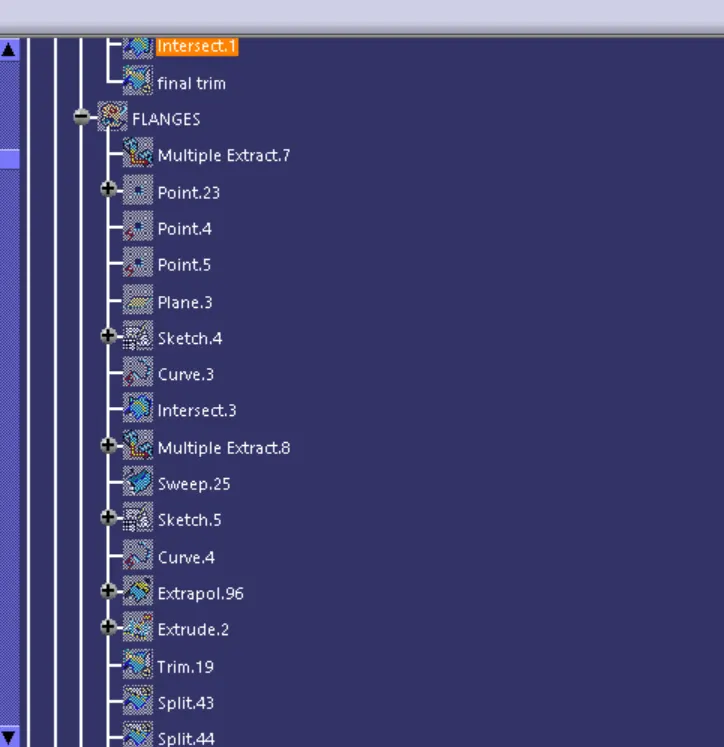
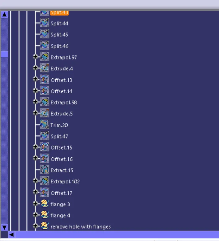
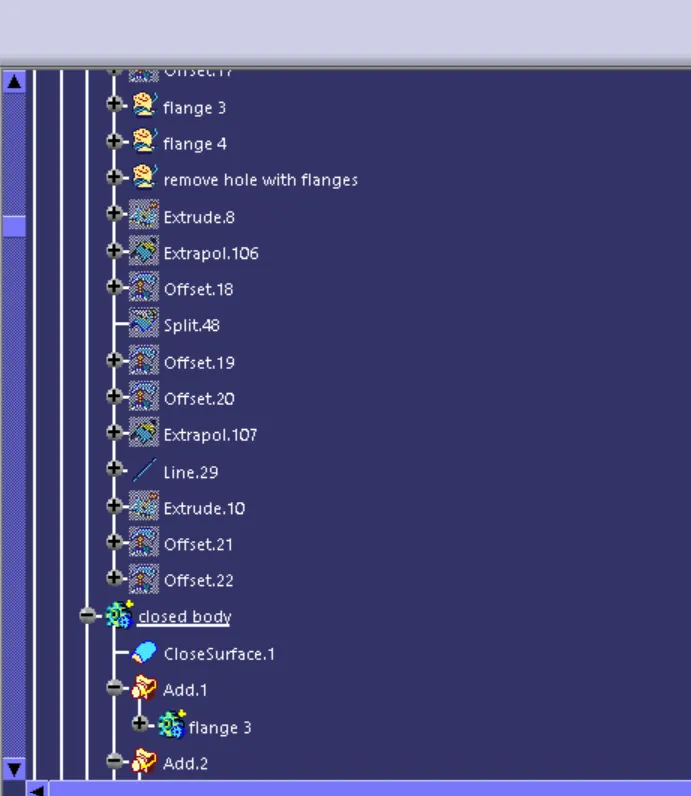
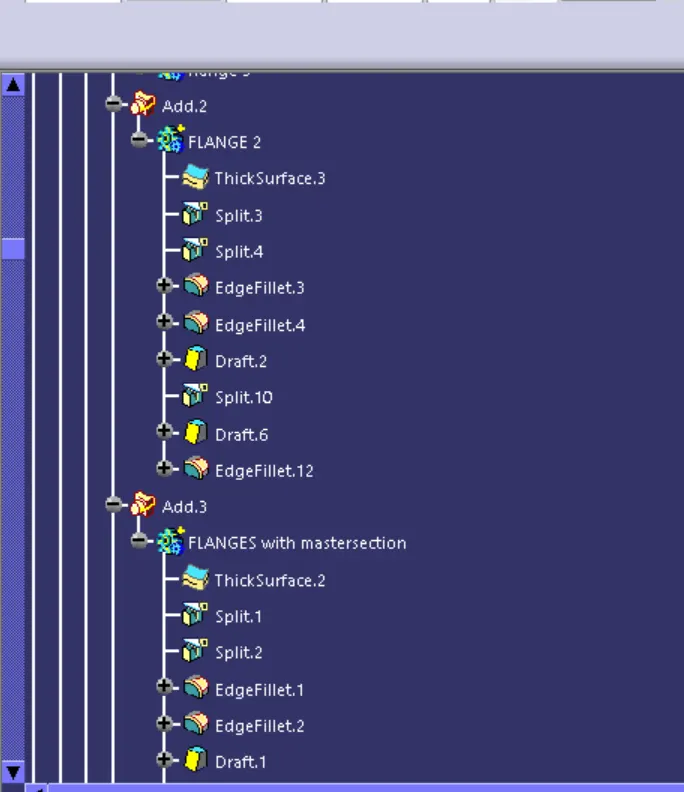
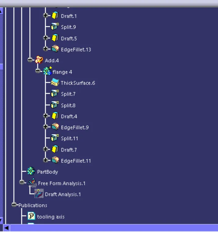
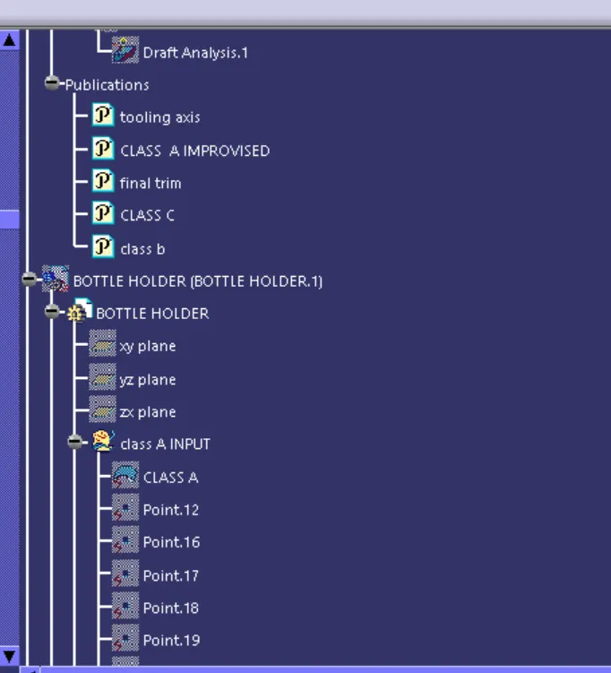
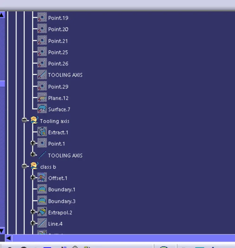
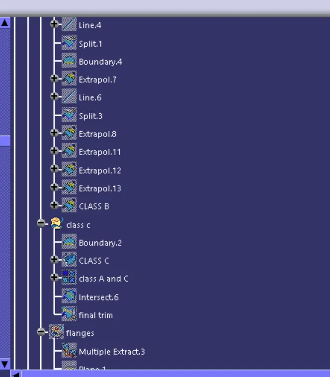
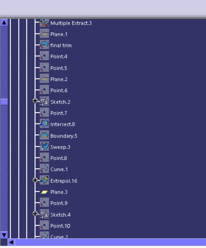
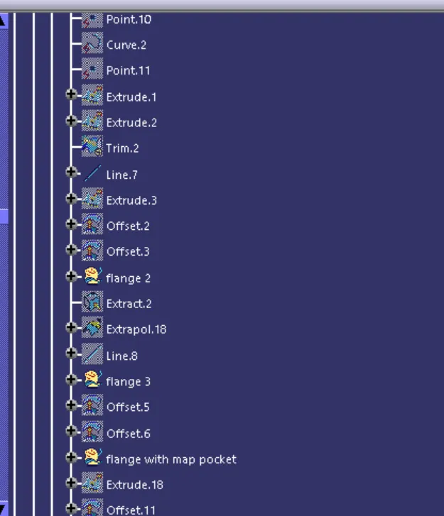
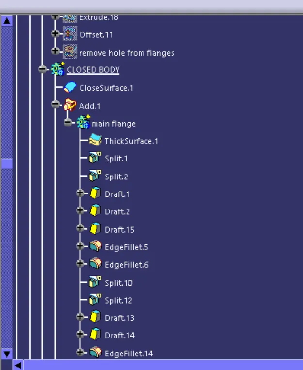
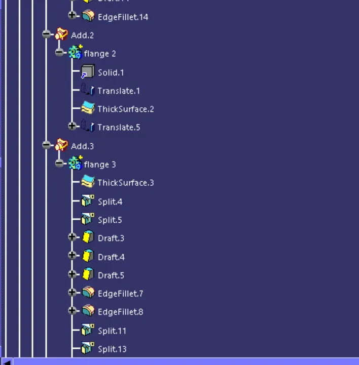
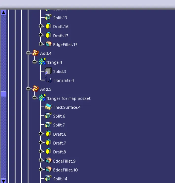
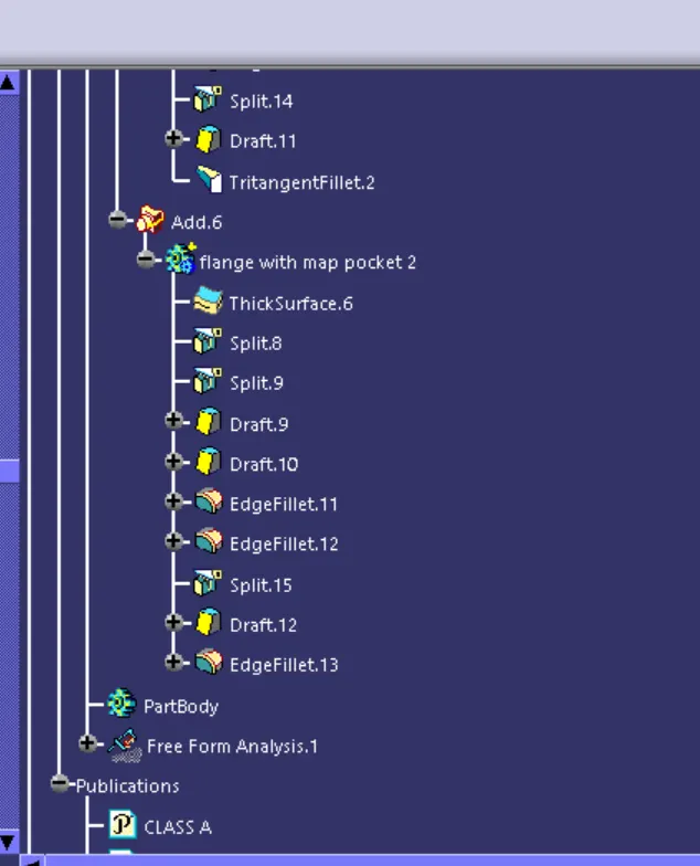
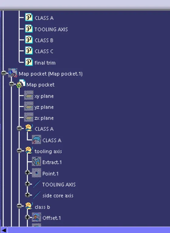
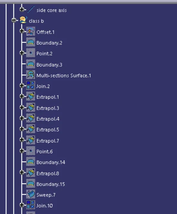
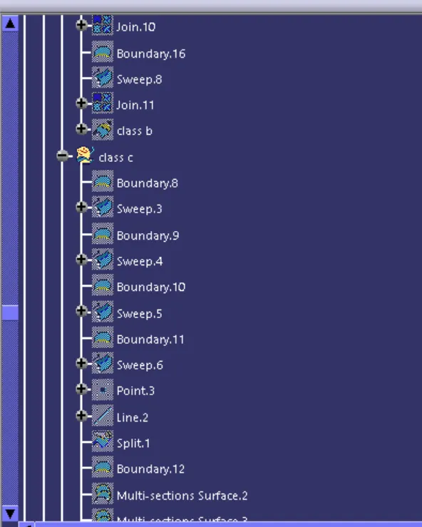
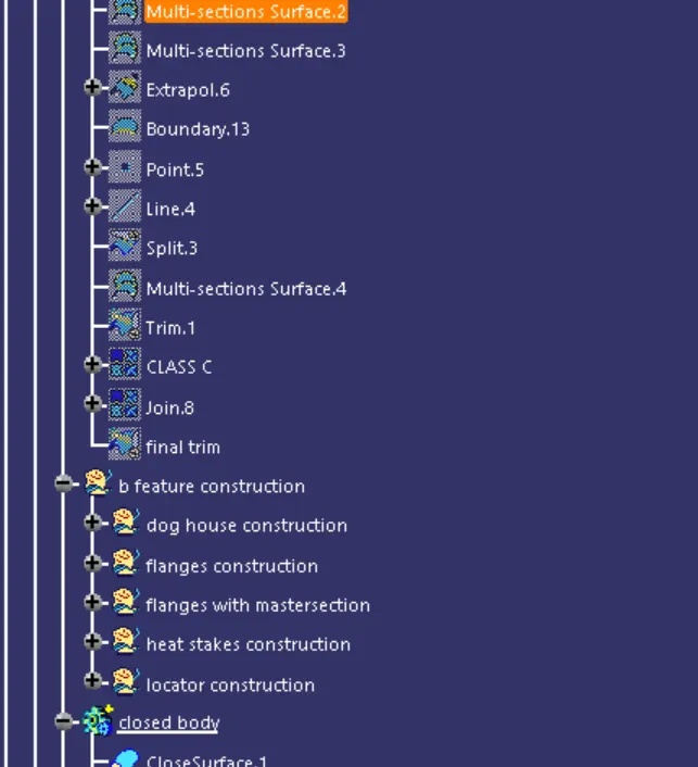

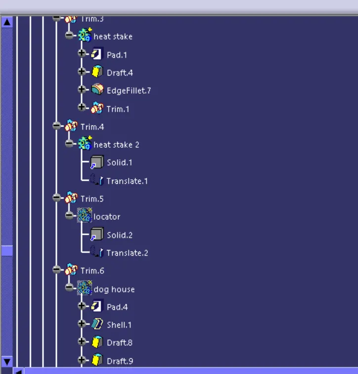
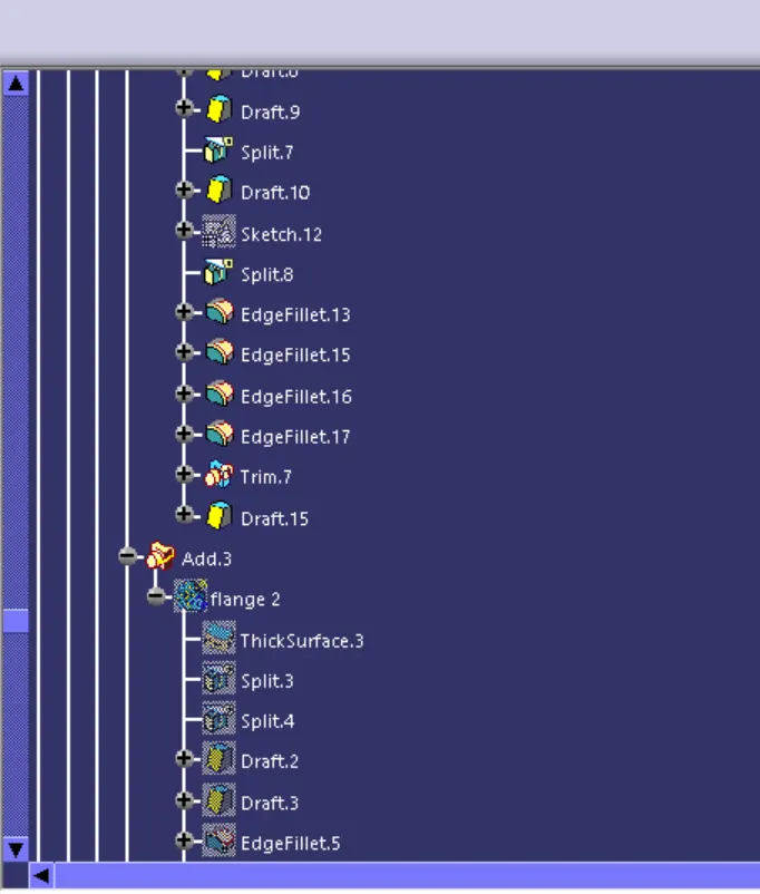
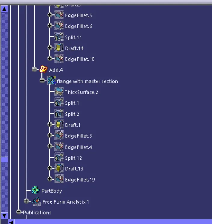
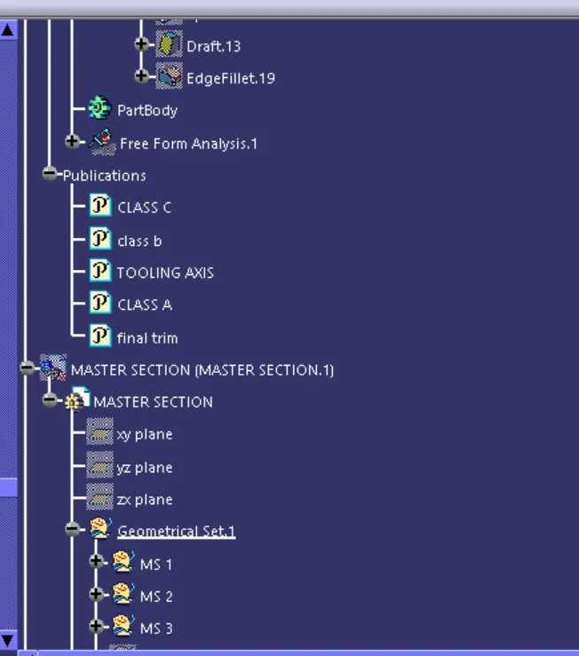
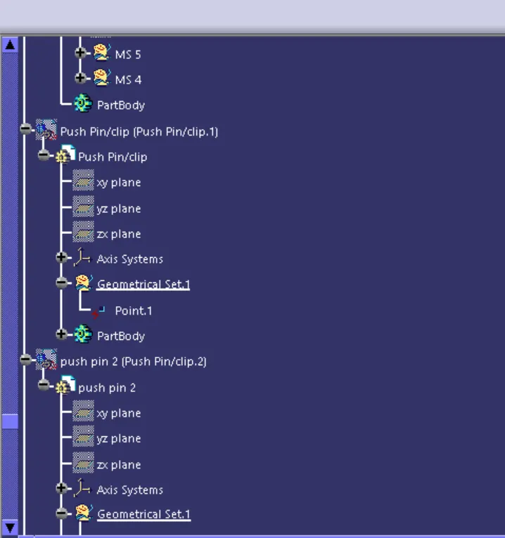
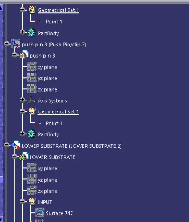
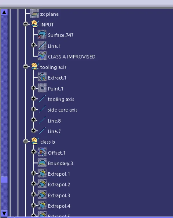
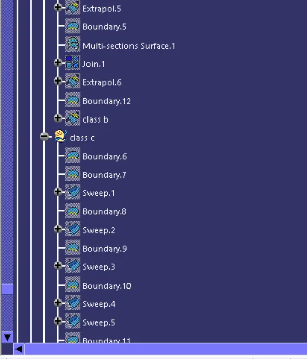
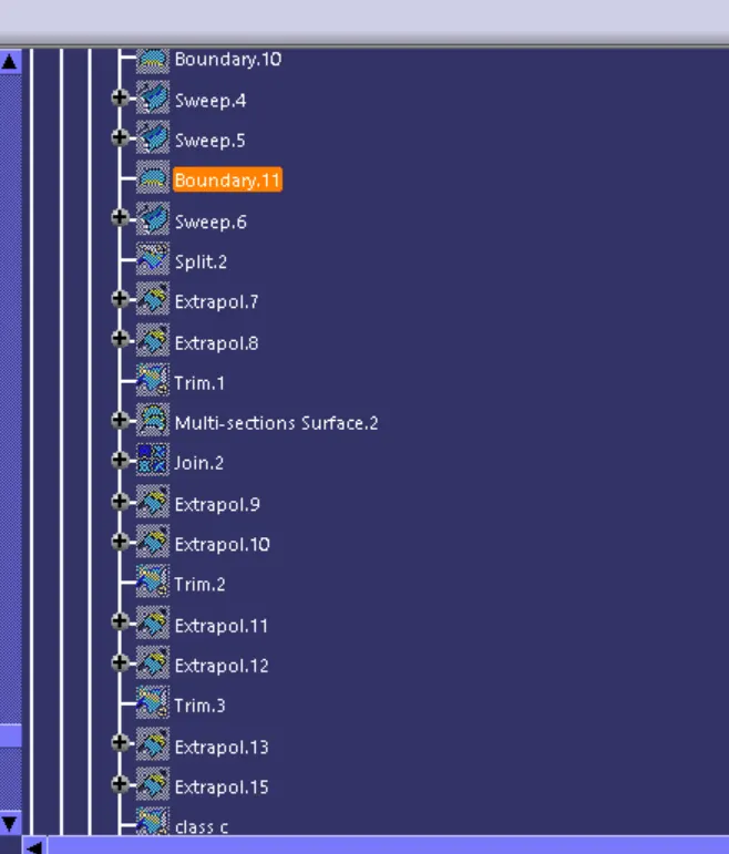
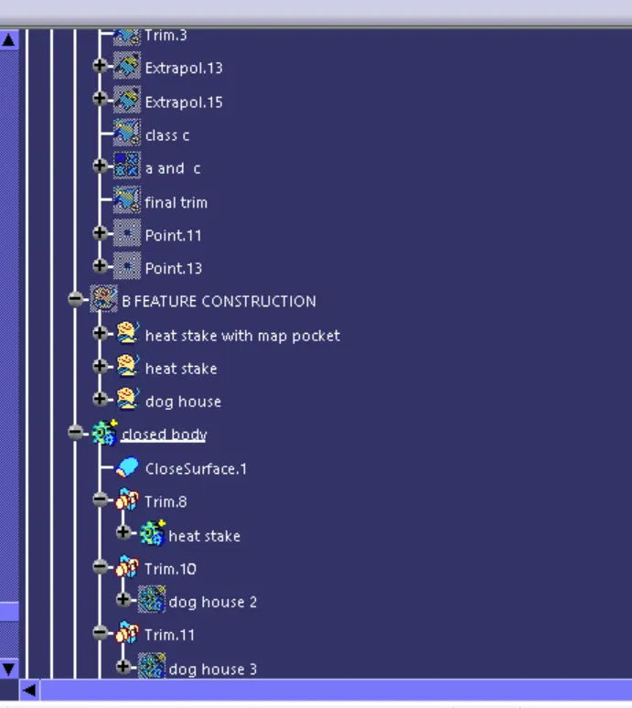
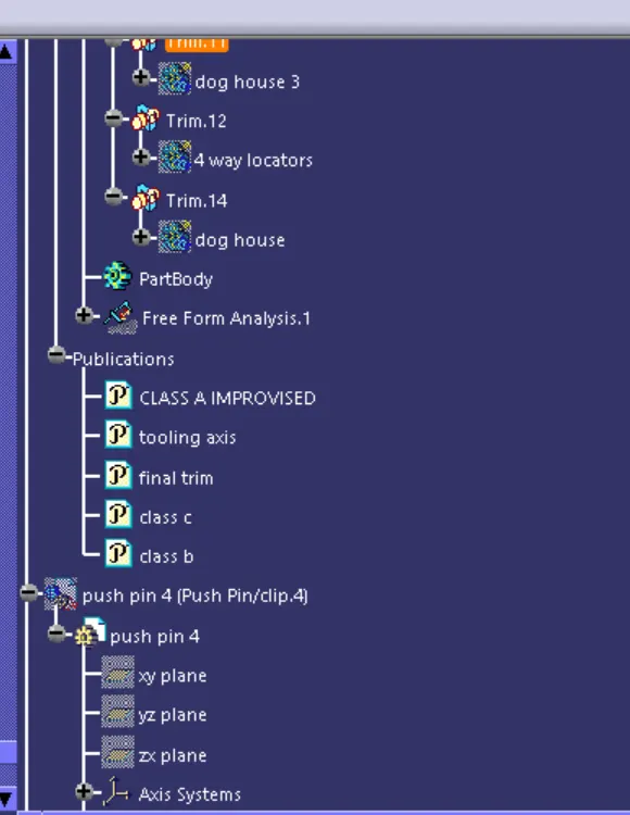
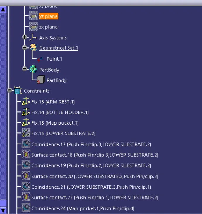
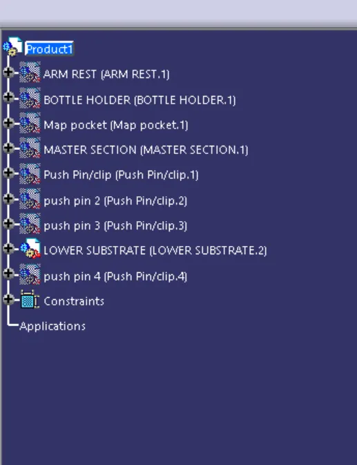
Door trim panel is the plastic part which is attached to the car door . It has mainy Four sub parts to make an assembly of door trim panel.
DOOR TRIM PANEL PARTS are :
1. Arm rest
2. bottle holder
3. map pocket
4. lower substrate .
FOLLOWING STEPS MAKE TO assembly of door trim panel
1. SEPARATE the surface into different parts and MAKE THE SOLID BODY OF given class A surface input
TO create the solid body of a surface , following steps need to be follow.
1. check any open boundar or not in CLASS A, if yes, improvised CLASS A
2. create tooling axis : It is the axis along with mold will moves.
3. check the draft analysis with 3 degree draft for the component, in order to check , that tooling axis which we have made, is clearing our component or not.
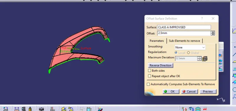
4. create CLASS B , by taking offset from CLASS A, BY 2.5 mm. In class b ,if any surface are not offset properly , repIR THOSE SURFACE BY using multisection, blend command and extrapolate to some distance in order to intersect with final trim .
5. create class C surface with reference from class A , by taking 3 degree positive draft.
6. join CLASS A and CLASS C.
7. TRIM the join A and C with extrapolated CLASS B surface.
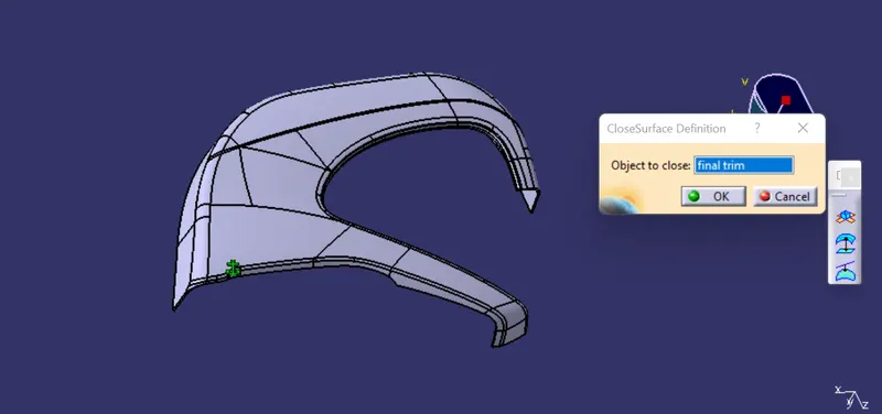
8. create the solid body of trim surface using close suraface option.
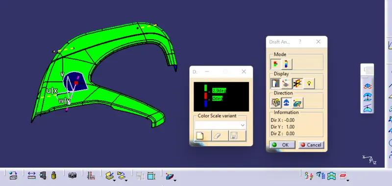
9. check the draft analysis of the solid body, to check our solid body is clearing with 3 degree draft which has provided.
ARM REST
class A
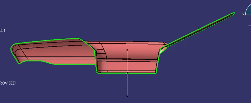
IMPROVISED CLASS A
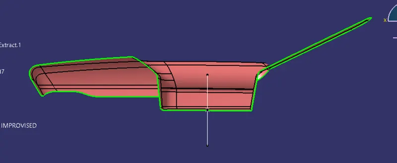
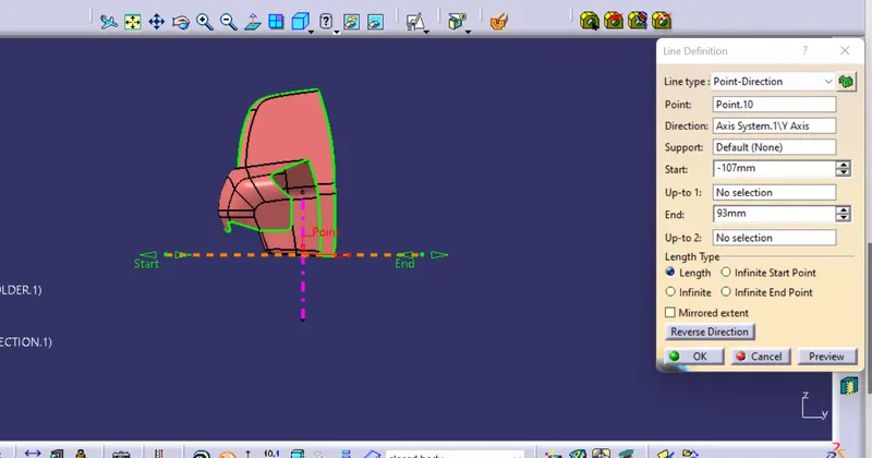
TOOLING AXIS : It is the axis along which core and cavity moves .
Main tooling axis : For clearing major part (As major parts is visible along z direction , so we will make tooling axis along z direction).
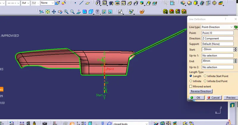
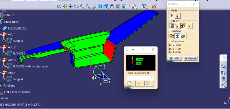
Side core tooling axis : For clearing side core ( AS side core part is not clearing with our main tooling component , so for side core, we will make another tooling axis).
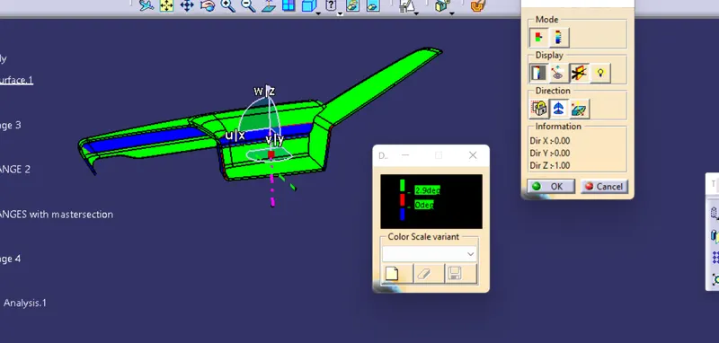
Draft analysis: It is used to check , along tooling axis which we have made , are clearing our component or not.
1. main tooling axis.
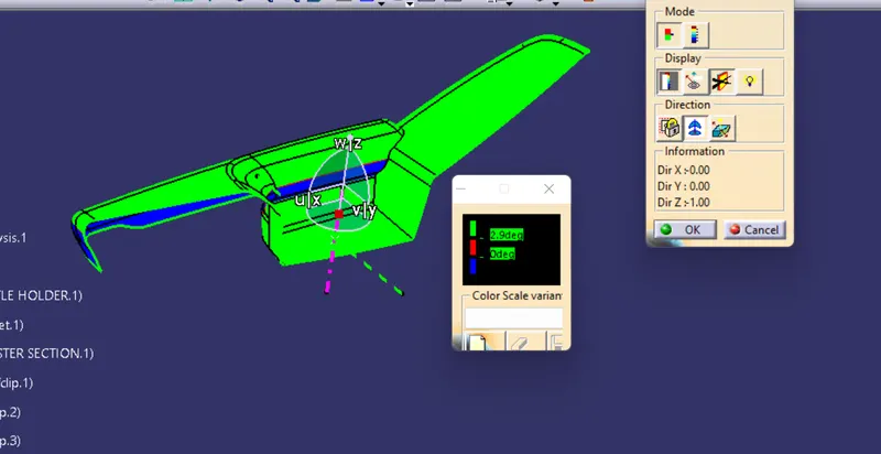
2. side core tooling axis.
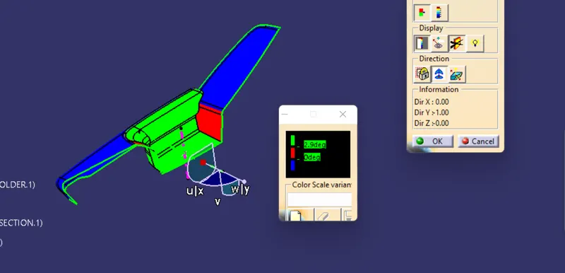
CLASS B SURFACE : It is the surface which is not visible to customer . It is offset by 2.5 mm.
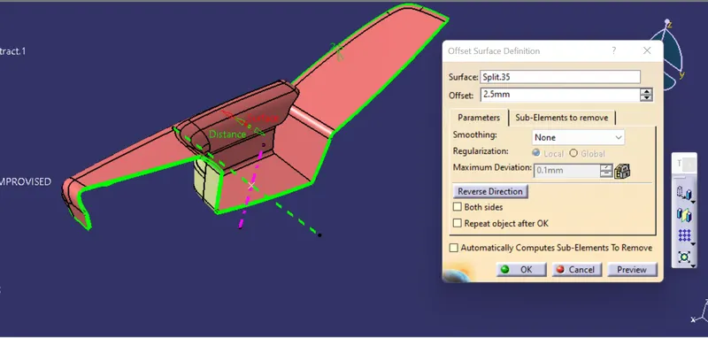
class c surface : it is used to join the class A and B surface.
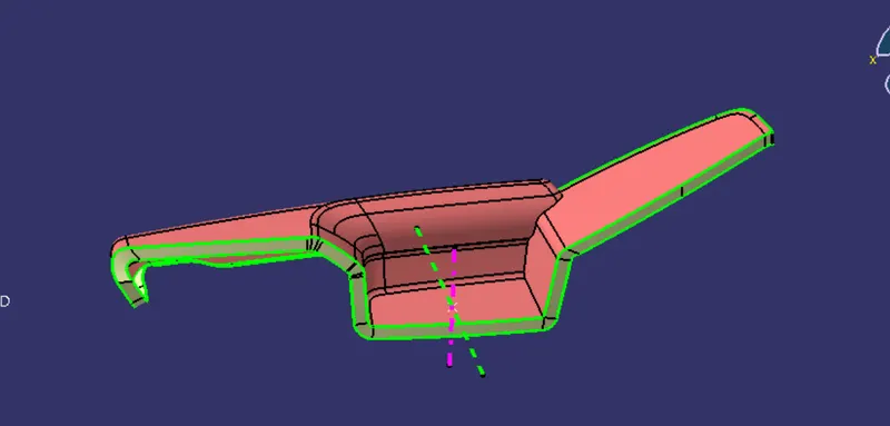
closed suraface :
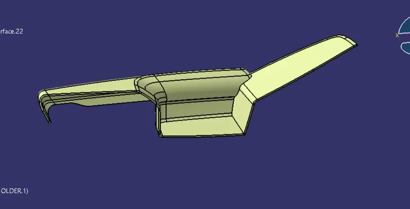
closed body : by using closed surafce method.
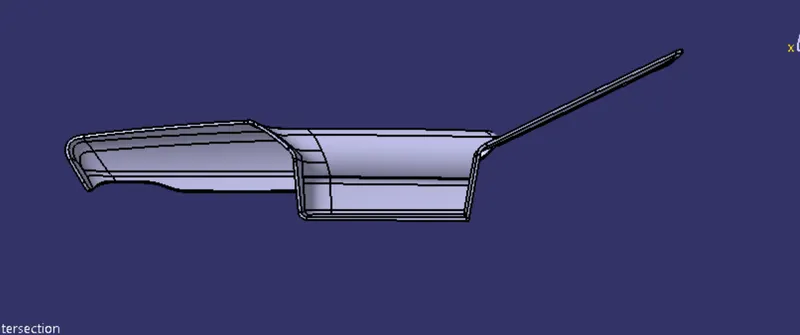
draft analysis for solid body.
for main tooling axis
for side core axis
2. BOTTLE HOLDER
CLASS A :
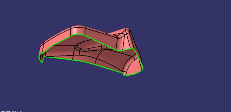
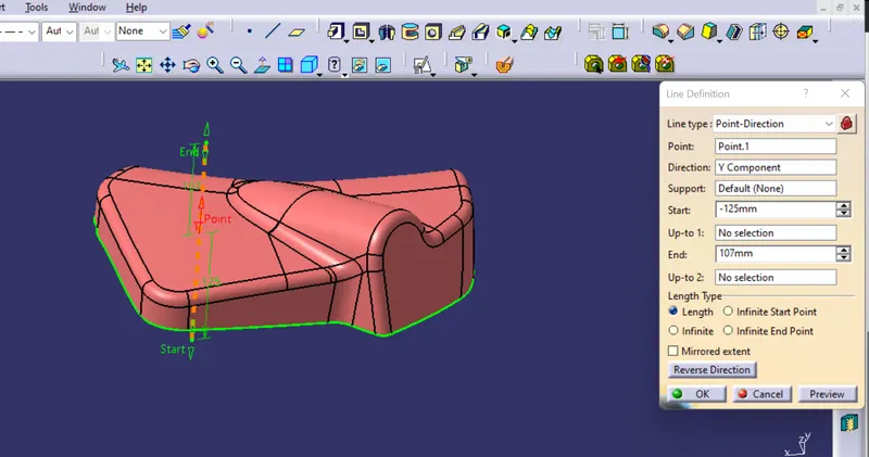
TOOLING AXIS : As major parts is visible along y direction , so we will make tooling axis along Y direction.
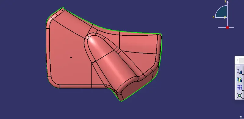
draft analysis for class A
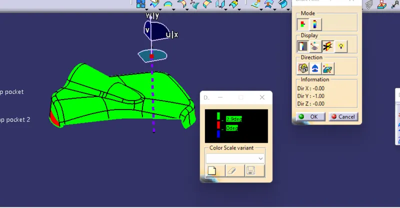
NOTE
As, we saw that from back side of this component is not clearing, hence styling team need to check this component.
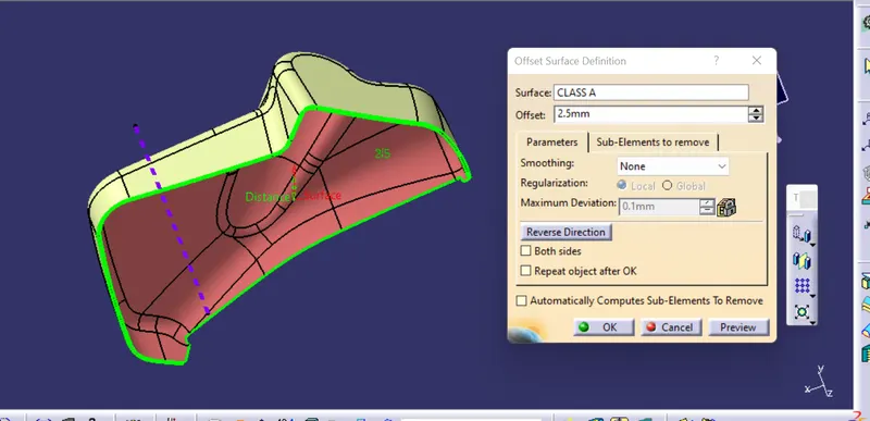
class b surface : offset 2.5 mm
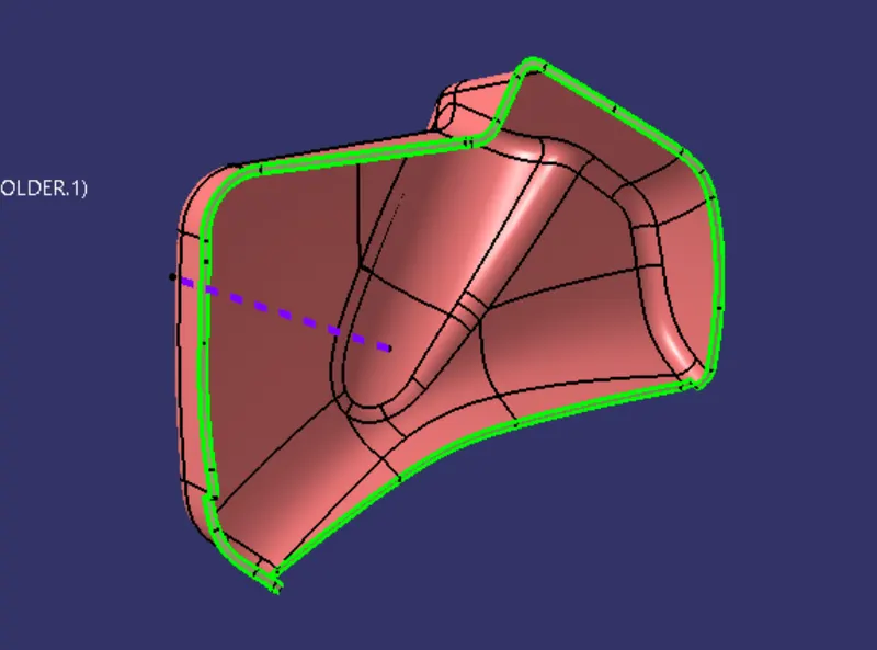
class c :
final trim close surface :
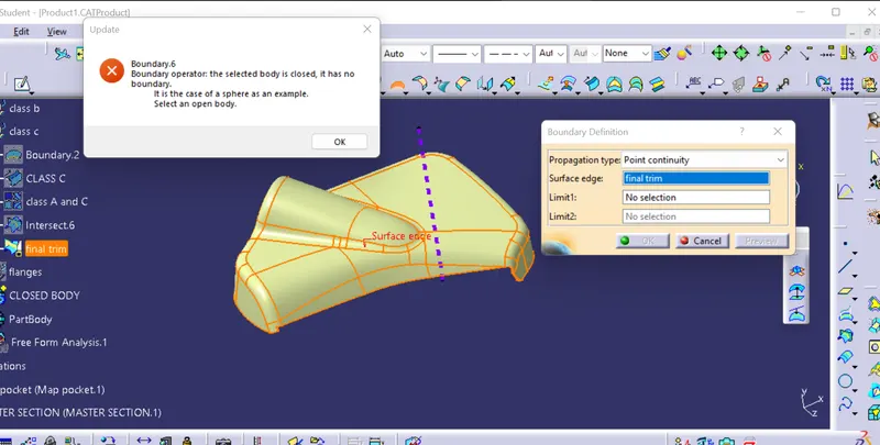
closed body : by close surface method.
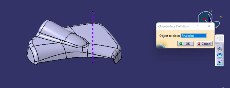
draft analysis of solid body
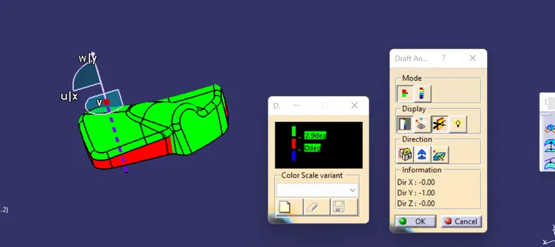
3. MAP POCKET
CLASS A
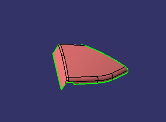
TOOLING AXIS :As we can see major component along Y direction , so we make the tooling axis along Y direction.
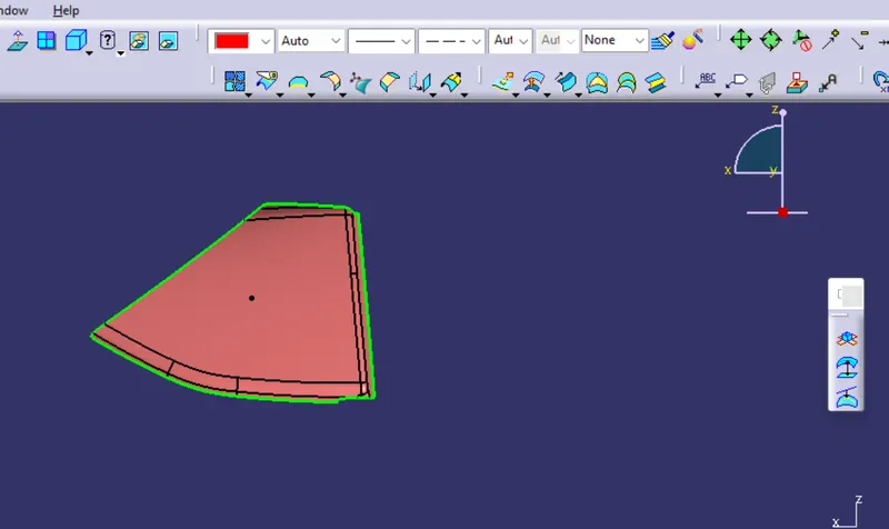
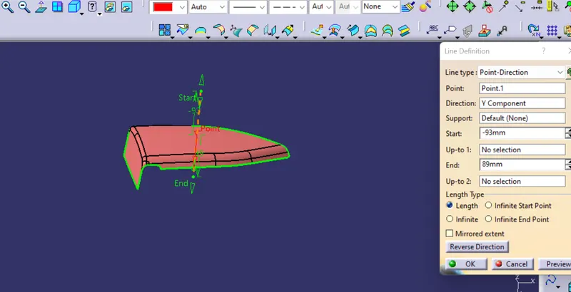
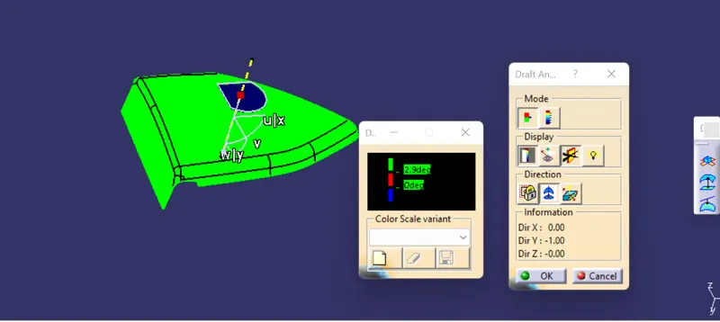
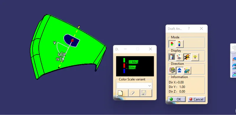
DRAFT ANALYSIS: Here we can see that , tooling axis which we have made is clearing our component with 3 degree draft.
CLASS B : OFFSET FROM CLASS A by 2.5 mm
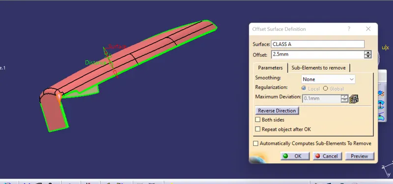
After offset , som fillet area are not offset properly , so to repair those surface, WE USE MULTISECTION COMMAND AND join them .
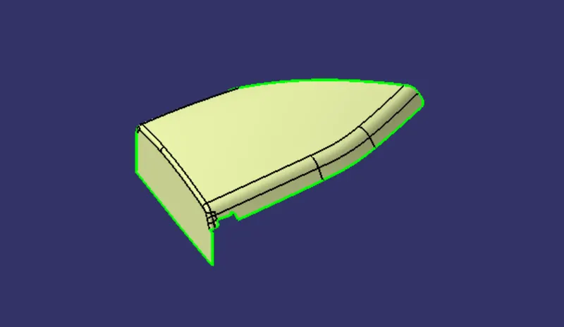
class c :
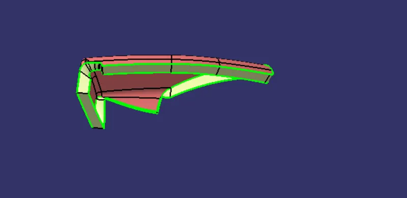
final trim : close surface
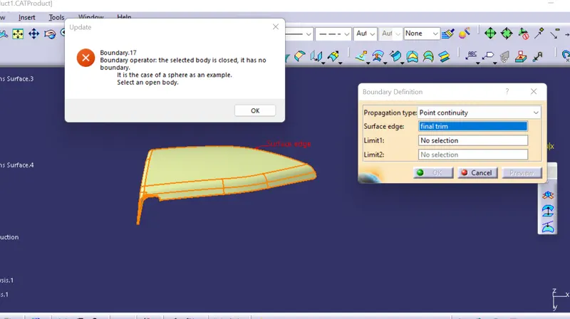
closed body : by using close surface method
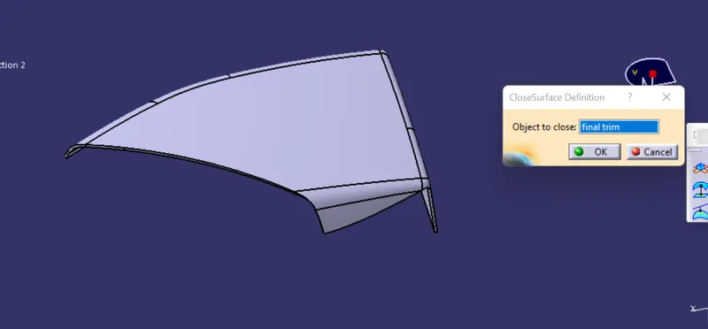
draft analysis :
4. Lower substrate:
class A :
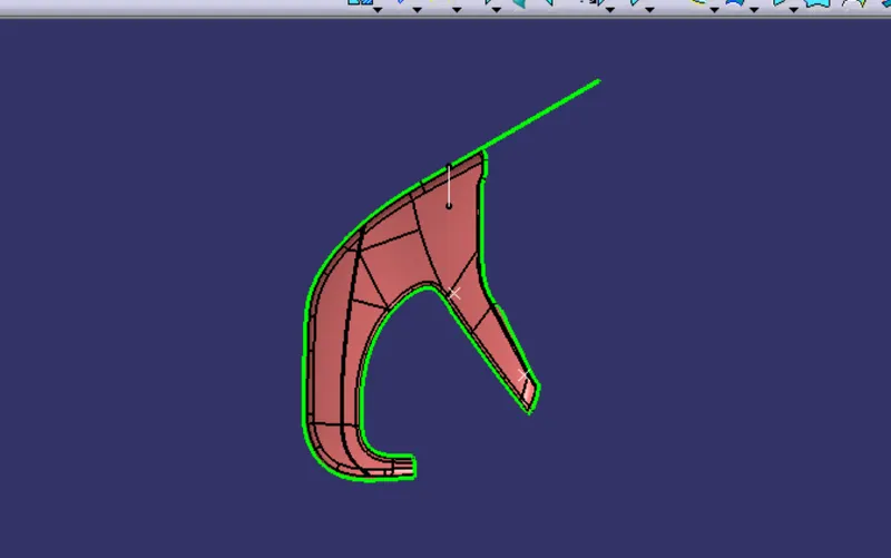
class A improvised
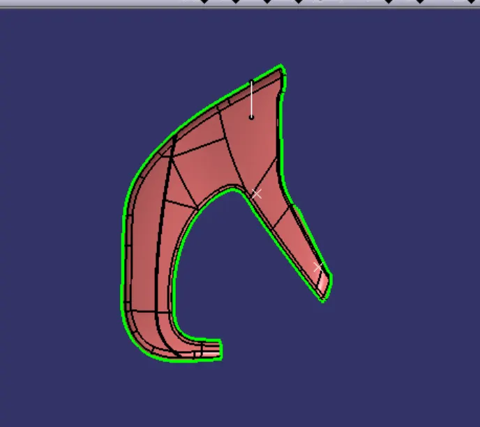
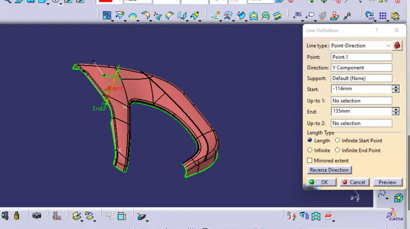
TOOLING AXIS :
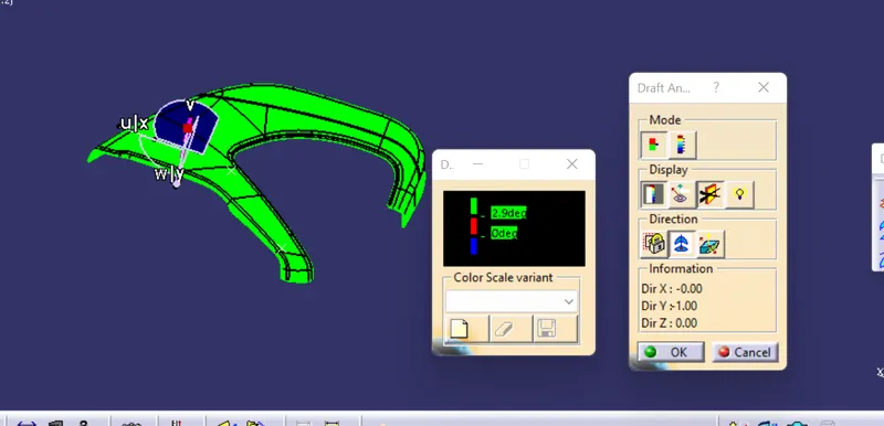
As we can able to see the component along Y Direction , so we made tooling axis along Y Direction.
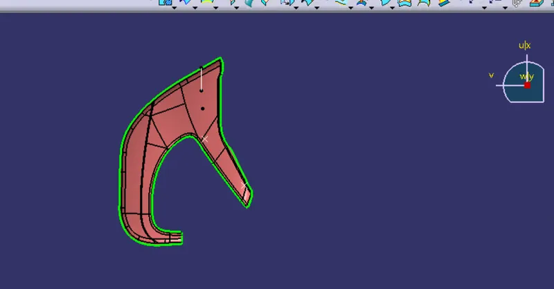
Draft analysis :
class b
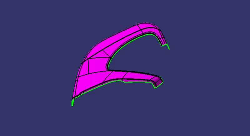
class c
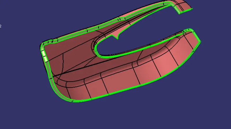
final trim AS close surface
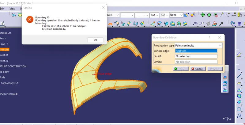
closed body :BY using CLOSE SURFACE METHOD
DRAFT ANALYSIS FOR SOLID BODY
NOW, as all the SOLID BODY parts of DOOR TRIM PANEL ARE MADE
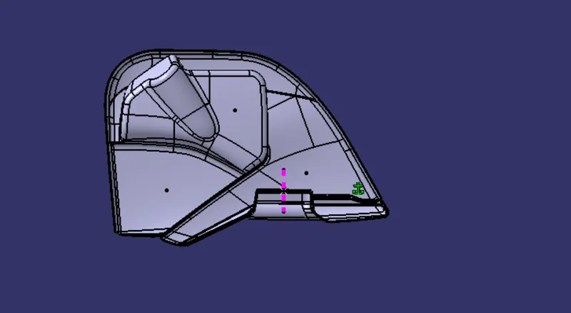
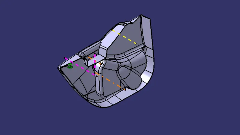
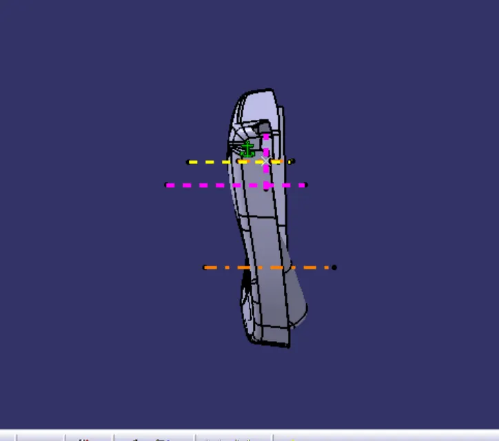
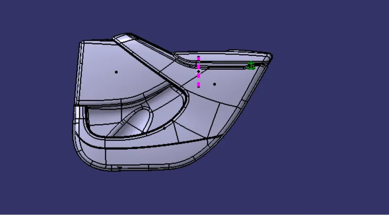
AFTER, WE nee to the mounting features as per design guidelines in the industry and with master sections
steps for creation of mounting features
1. we need fix all first , so that our parts shoud not move .
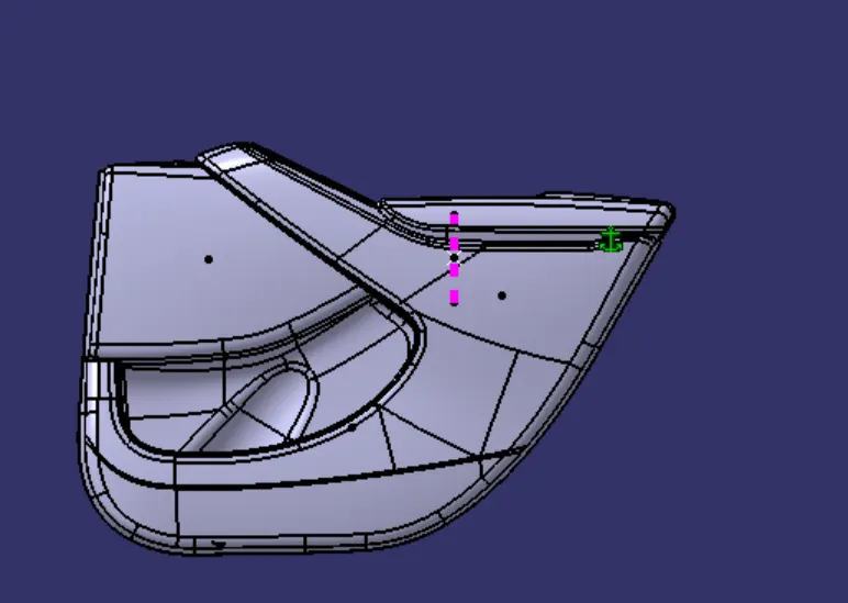
2. WE will creates B SIDES FEATURE : It is done in order to provide strength to the component and join the two different component. It is made where surafce is not visible to customers, means CLASS B suraface.
1. heat stake : it is a prmanent join techniques of two different component by heat addition to the heat stake protrusion above the counterpart . We create heat stake with ribs as supporting features to heat stakes to increase the strength .

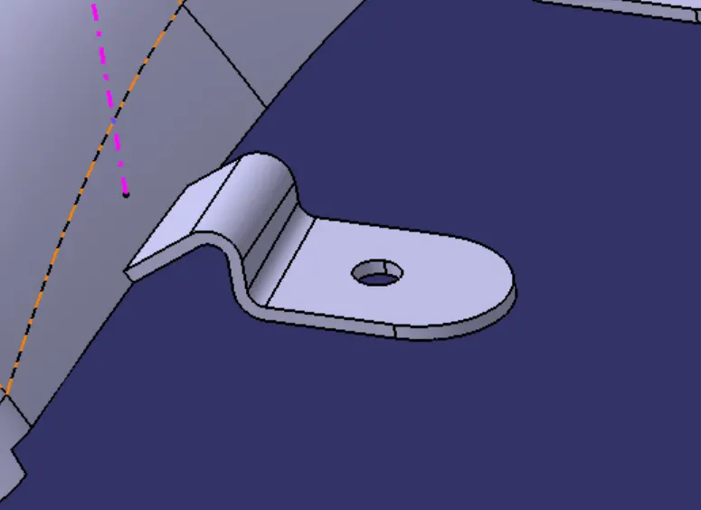
2. COUNTER PART (flanges ) : It is used to connect two component with having heat stakes , After heat stake melting , that melting part will occur on the flanges , and by this two component will join.
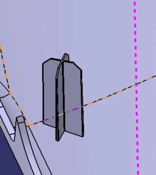
3. LOCATOR : It is a features which is used to arrest a degree of freedom while the component are being assembled. Its height is greater than heat stakes.
There are 6 DEGREE OF FREEDOM
3 transational
3 roational
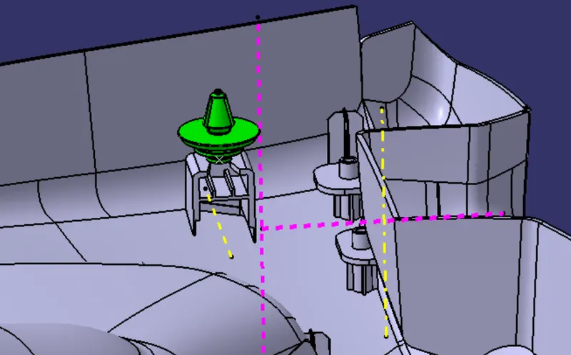
4. DOG HOUSE : It is a features which supports the other features like heat stakes, screw bosses and locators to locate them at a certain height , where we cannot violate the design for features.
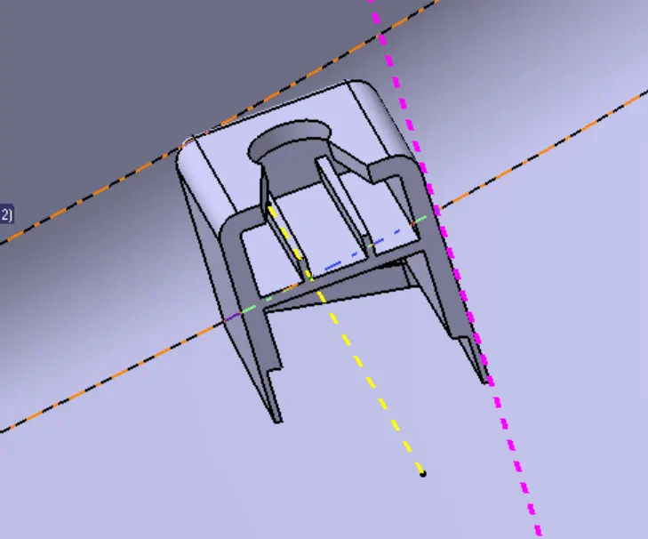
NOTE : For providing draft to the b features side, 0.5 degree draft need to be given , in orderto clear the b sde features.
we will create mounting features with given master section first
MASTER SECTION : It is the reference , which has been taken from the previous component, so that exact position , we can achieved with less cost optimisation . It is used to design a component.
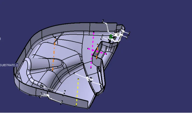
1. Master section is , to connect LOWER SUBSTRATE TO ARM REST
heat stakes in the lower substrate and flanges in the arem rest.
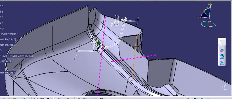
2. MAP POCKET WITH LOWER SUBSTRATE
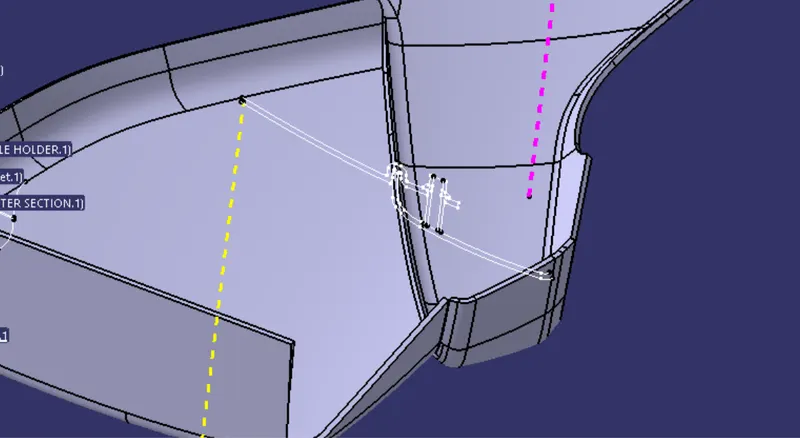
3. mastersection of flanges in map pocket
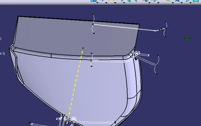
creation of b features with 0.5 degree draft
HEAT STAKES and dog house IN THE LOWER SUBSTRAE
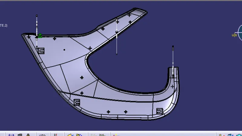
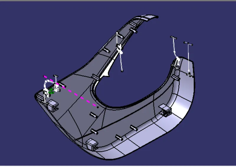
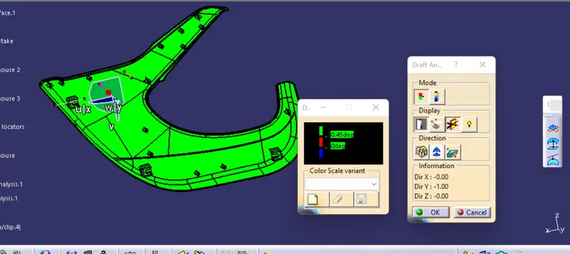
draft ANALYSIS FOR B SIDE FEATURES
FLANGES IN THE ARM REST
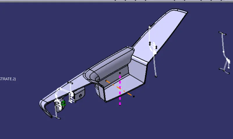
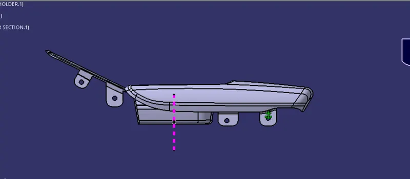
LOWER SUBSTRATE AND ARM REST CONNECTED THROUGH FALNGE AND HEAT STAKES.
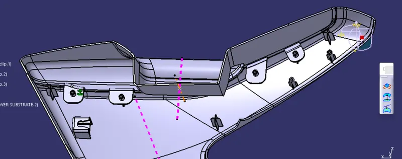
draft analysis , to check the draft analysis with 0.5 degree in b sides features, we will use side core tooling axis.
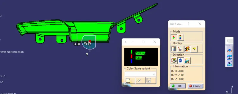
map pocket flanges , to connect with lower substratre
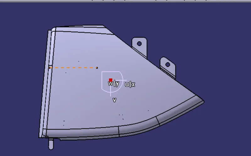
b side features on map pocket
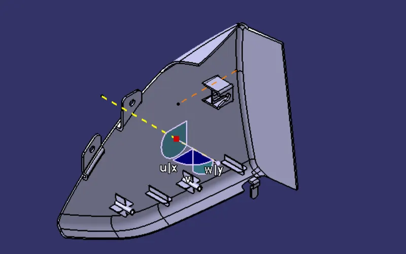
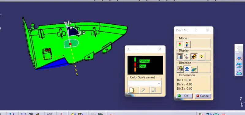
for clearing coring part of dog house , we have side core axis
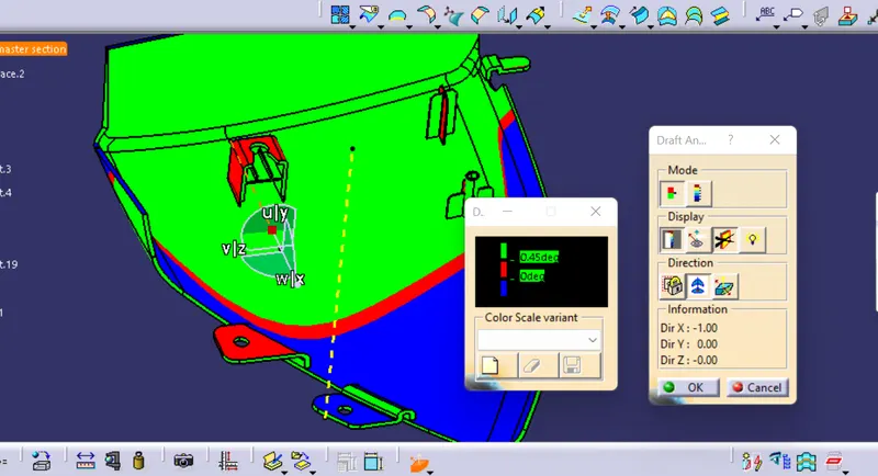
BOTTLE HOLDER FLANGES TO CONNECT WITH MAP POCKET AND LOWER SUBSTRATE
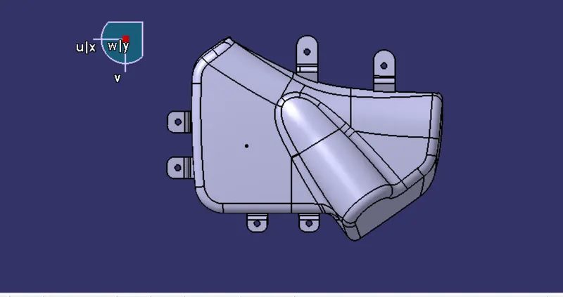
DRAFT ANALYSIS FOR FLANGES
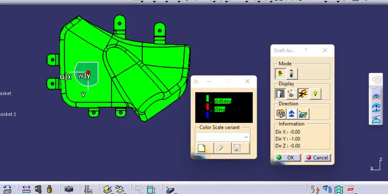
AFTER CREATING MOUNTING FEATURES
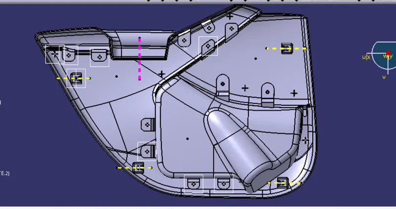
IN THE DOG HOUSE, WE HAVE TO ATTACH PUSH PIN , IN order to join with the sheet metal door.
views
isometric views
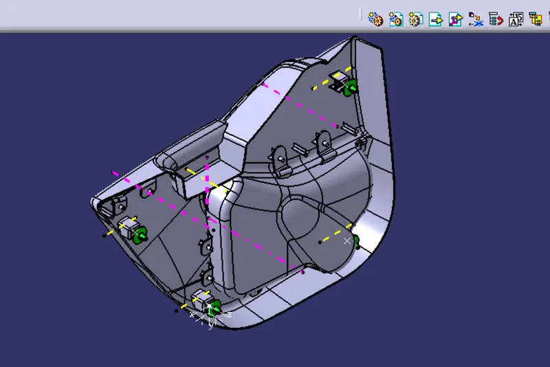
front views
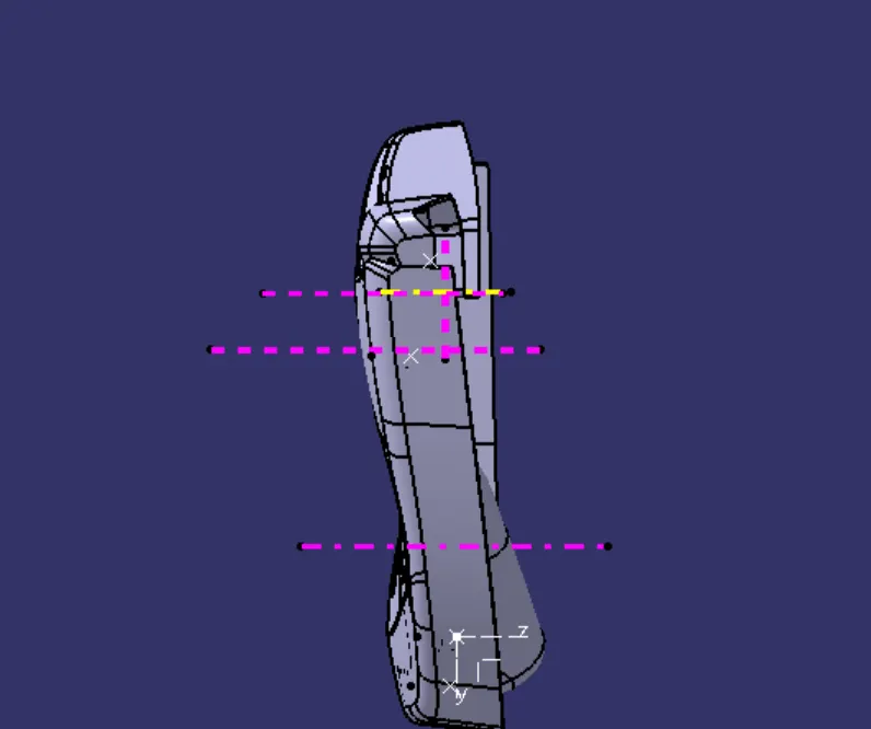
side views
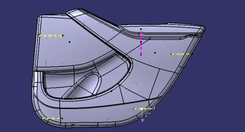
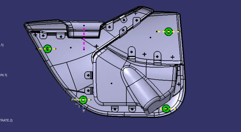
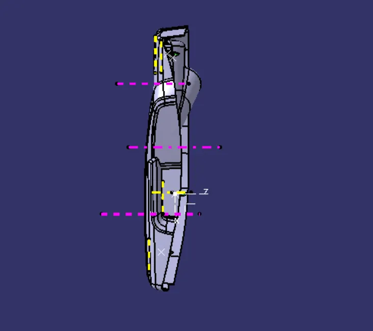
top views
CONCLUSION : I have made the door trim pannel assembly with the help of catia v5 software, A detailed report has been prepared and all the part bodies and assembly has been attached to the challenges successfully.