Week 11 - Final project
Objective: Development of Car door trim panel with proper attachment strategy and performing draft analysis on each part of the door panel.
Description:
The Entire project is completed on CATIA V5 R21 software.
Door trim panel provides the aesthetic look that is required for the door panel. Besides this it also covers the electric circuits, wirings, other door mechanisms behind it. It is attached to the sheet metal part of the door panel through the fixation features (like Push pins, Heat stakes and other locking mechanisms). The materials like Acrylonitrile Butadiene styrene (ABS), Polypropylene (PP), Polyvinyl chloride (PVC) are used in manufacturing of the door trim and other interior trims of a car.
Approach for developing the Door trim panel:
- Extract the required portion of Class A and modify it, if required.
- Creating tooling axis.
- Perform Draft analysis on the class A surface.
- Create Class B surface.
- Join Class A & C surfaces and trim it along Class B surface.
- Finally, we get the surface body of that portion which can be made as a solid component using the ‘Close surface’ option.
- Creation of B-side features.
- Perform Draft analysis on final solid component.
Door trim Panel:
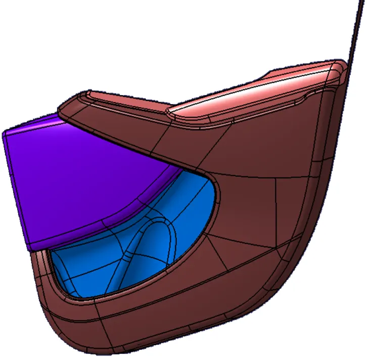
From the given input surface, the required portions are extracted and then Class B & C surfaces are created accordingly to form a surface body.
 |
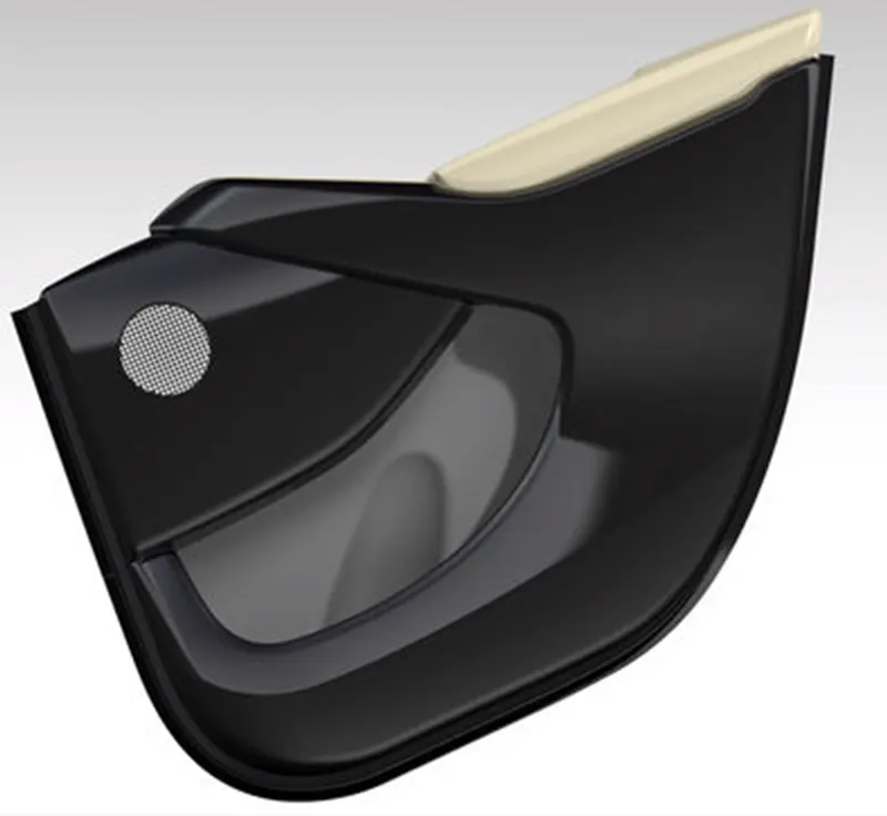 |
| Door trim panel Class-A surface. | Door trim panel plastic component |
Class A surface:
When a concept sketch is ready then an aesthetic surface is created in ALIAS software which is known as Class A surface. This surface is considered as the input by the product engineers and solid component is done by following this surface, if any error is observed while performing Draft analysis then the Class A should be modified. But the product engineers can’t do this, all required modifications need to informed to the Class A designing team and get the modification done.
Tooling Axis:
It is the axis which helps us to know, in which direction will the core and cavity need to be ejected so that the plastic component is not distorted while ejection. Tooling axis for any surface can be created by following method:
Draft analysis toolbar is opened the compass is placed on the surface of the component and the compass is activated by clicking the compass button on the draft analysis dialog box.
Then the compass is rotated holding its top portion unless the colour assigned for the required draft angle is not observed, once the colour is observed on entire surface/body we lock the compass position and a line is drawn along this compass direction and the line created will be our tooling axis for that surface/component.
Draft analysis:
Draft analysis is performed in order to know whether the component can evidently be ejected through the tooling axis. There is colour bar in draft analysis which helps us to recognise the portion of each surface, for example: If the Green colour is assigned with draft angle with 3 or more degrees and Blue colour is assigned with draft angle with 0 to 3 degrees, If the surface turns Green then it satisfies the draft conditions if not then it needs to be modified.
Draft analysis on different Class A surfaces:
1. Lower Substrate:
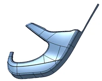
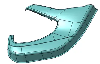
The given Class A surface is modified by adding the flange so that the component can be easily attached to other parts.
 |
|
| Given Class A surface. | Class A surface modified. |
Draft analysis:
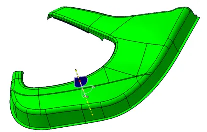 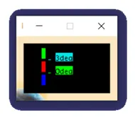 |
| Draft condition is satisfied. |
2 Map pocket:
This portion is divided into two parts namely,
a Top map pocket:
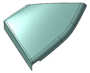
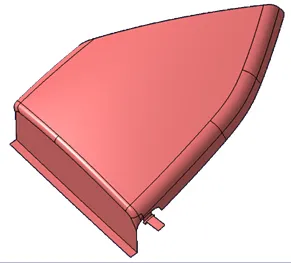
The given class A is modified by adding flange by following master section.
 |
|
| Given Class A surface. | Class A surface modified. |
Draft analysis:
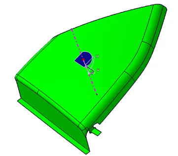 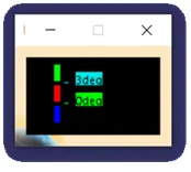 |
| Given Class A surface. |
b Bottom map pocket:
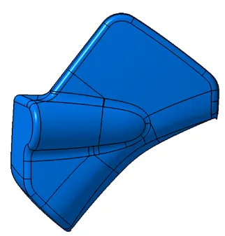 |
| Given Class A surface. |
Draft analysis:
Draft analysis is carried out and by observing the results, we can say that some portion of the surfaces is not satisfying the draft condition.
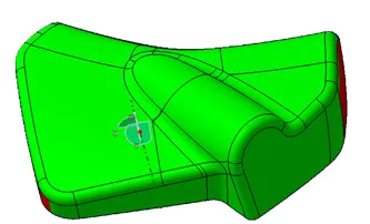  |
| Draft condition fails at particular portion. |
The red patches indicates that draft condition fails (lees than 3 degrees) at that portion. We need get that portion modified by the Class A designers team.
3 Arm rest & Switch Bezel:
a Arm Rest:
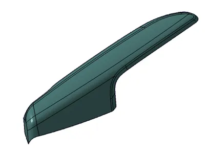 |
| Given Class A surface. |
Draft analysis:
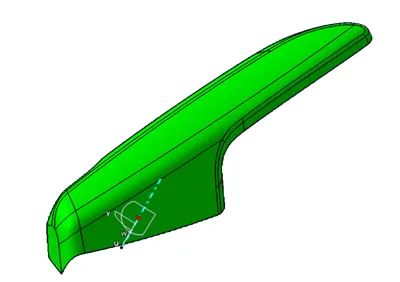  |
| Draft condition is satisfied. |
b Switch Bezel:
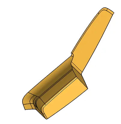 |
| Given Class A surface. |
Draft analysis:
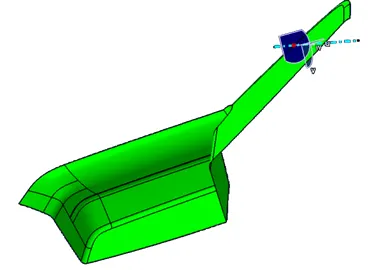 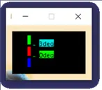 |
| Draft condition is satisfied. |
GENERAL STEPS INVOLVED IN CREATION OF PLASTIC COMPONENT:
The Solid plastic component of each part is created by following the below steps:
a. Class B surface is created by giving offset of 2.5mm (from Master section) and extrapolating the edges bit wider than class A surface. When the class A surface is offset for 2.5mm there will be missing of cetain portion of the surface which need to be recreated using proper surface tools.
b. Class C surface is created by providing sweep angle of 3 degrees with tooling axis or sweep is created at 90 degrees with reference to the surface either of one is used accrding to the requirement.
c. Then the Class A & Class C surface are joined and trimmed with the Class B surface, by which we get the SURFACE BODY.
d. The surface body is converted to solid by using the ‘Close Surface’ option.
e. B-side features like Heat stakes, Ribs, Doghouse, etc are created.
LOWER SUBSTRATE:
Class B surface:
Class A surface is offset for a distance of 2.5mm. The are voids created after offset, which need to be filled/recreated by usinfgthe proper surface tools.
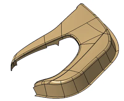 |
| Class B Surface. |
Class C surface:
Using the Sweep of 3 degrees along the tooling axis or 90 degrees with reference to surface is used and Class C surface is created.
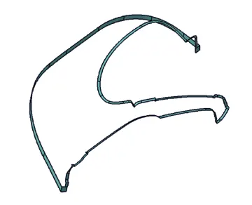 |
| Class C Surface. |
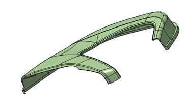
Surface body:
First the Class A & C surface are joined together and then trimmed with Class B surface.
 |
|
| Class A & C surface joined. | Class A & C trimmed with B surface |
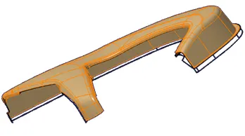
Solid Component:
The surface body created is converted to solid component using the 'Close Surface' option.
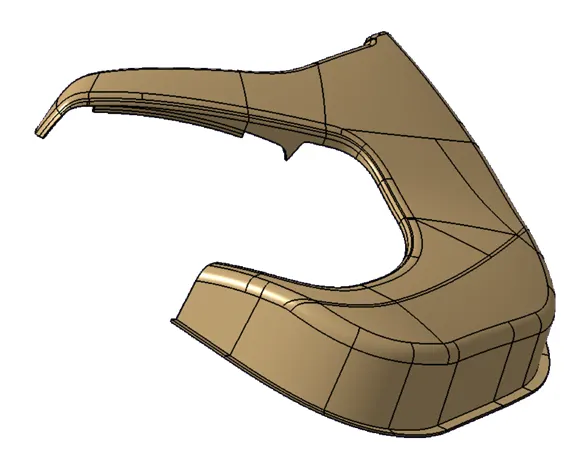 |
| Lower substrate Surface body |
B-side features:
RIBS:
Ribs are the engineering features which are present on the B-side of a plastic component and the main purpose of using them is to provide strength to the plastic components.
Steps involved in Rib designing:
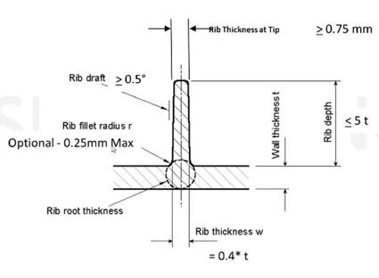
Ribs are created using the following guidelines and numerical values.
Numerical values used in the rib design by following the design rule.
- Thickness(t) = 2.5mm.
- Rib draft = 0.5 degrees.
- Rib fillet radius(r) = 0.25mm.
- Rib root thickness should be > 30% of Thickness.
- Rib thickness(w) = 0.4*2.5 = 1mm.
- Rib height = 5*2.5 = 12.5mm (considering the min value).
 |
DOG HOUSE:
It is an engineering feature used as supporting feature. Sometimes other engineering features likes snaps, locators etc. are mounted on them so that they are placed at particular height.
The main features of the Doghouse are:
- Prevents Sinkmarks.
- Engineering features perpendicular to the surface can placed on the doghouse.
Guideline to be followed while designing the Doghouse:
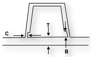 |
Doghouse wall thickness at the intersection of the part wall (C) Should be 40% or less than the main wall stock (T).
C= 0.4*2 = 0.8mm.
B= 3 to 6mm.
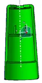
The outer surface of the Doghouse is cleared along the main tooling axis of the doghouse(axis in white colour) and the inner portions are cleared along the side-core axis(axis in purple colour). Finally, the draft condition of 0.5 degrees is satisfied, as shown in below pictures.
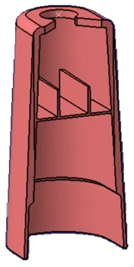 |
|
| DOG HOUSE | |
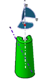 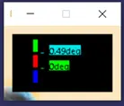 |
|
| DOGHOUSE CLEARING ALONG MAIN TOOLING AXIS | DOGHOUSE CLEARING ALONG SIDE CORE AXIS |
HEAT STAKES:
Heat stakes are the engineering features which are on the B-side of the plastic component and are used as attachment feature with the adjacent plastic component by the process of heat staking. The ribs are provided to the heat stakes with heights above 20mm(to provide strength), ribs are created following the guidelines of the ribs. All heat stakes satisfy the draft condition of 0.5 degrees.
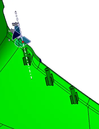 |
| Heat stakes satisfy the draft condition of 0.5 degrees. |
Draft analysis on Final Solid component.
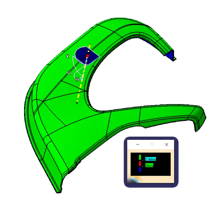
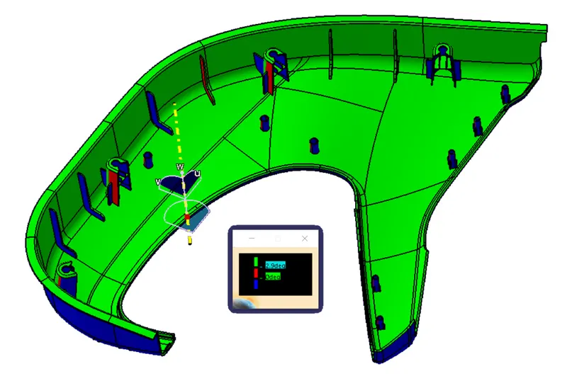
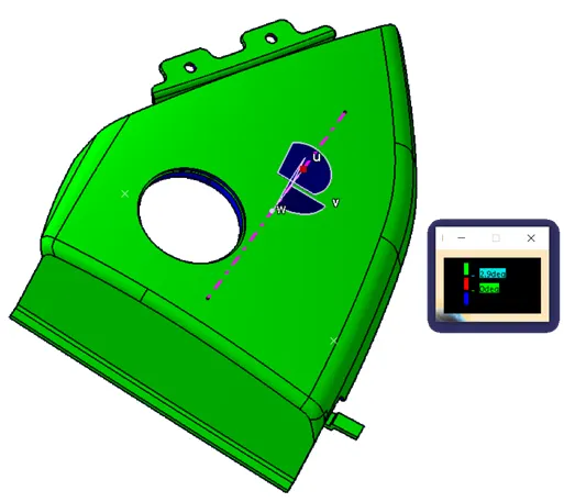
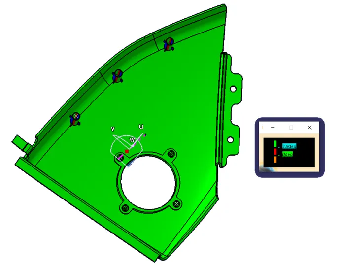
Draft angle of 2.9 degrees is set in the dialogbox because the colour changes only if the angle is above 3 degrees.
 |
|
| Draft analysis for solid component (3 degrees) | |
TOP MAP POCKET:
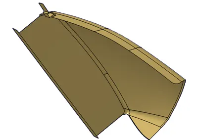
Class B surface:
Class A surface is offset for a distance of 2.5mm. The are voids created after offset, which need to be filled/recreated by usinfgthe proper surface tools.
 |
| Class B Surface. |
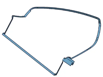
Class C surface:
Using the Sweep of 3 degrees along the tooling axis or 90 degrees with reference to surface is used and Class C surface is created.
 |
| Class C Surface. |
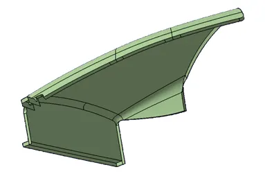
Surface body:
First the Class A & C surface are joined together and then trimmed with Class B surface.
 |
|
| Class A & C surface joined. | Class A & C trimmed with B surface |
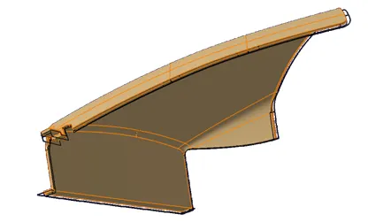
Solid Component:
The surface body created is converted to solid component using the 'Close Surface' option.
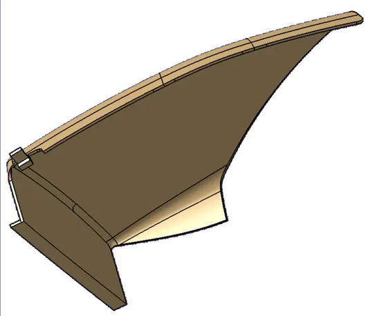 |
| Top Map pocket Surface body |
B-side features:
Screw Boss:
Screw Bosses are used to aid in the assembly of molded parts by providing a channel for a screw.
D=8.4mm
d=3mm.
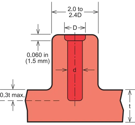 |
| Screw boss design. |
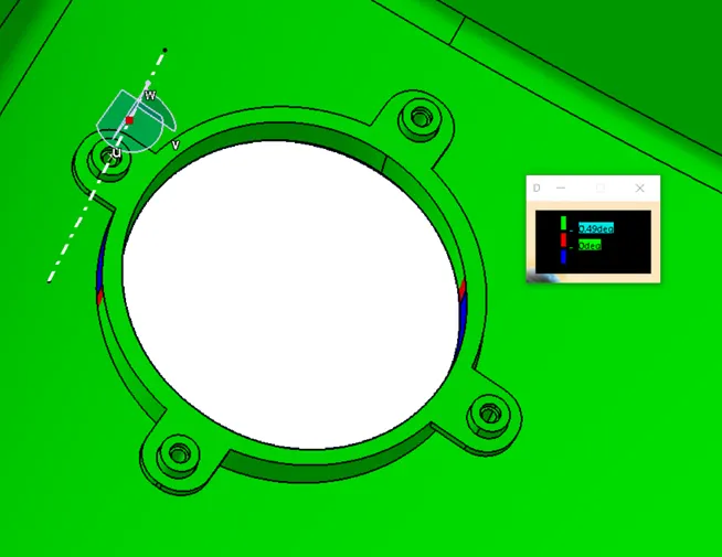 |
|
| Screw bosses and the flanges of the speaker slot satisfy the draft condition of 0.5 degrees | Heat stakes satisfy the draft condition of 0.5 degrees. |
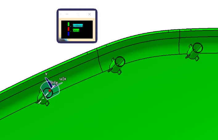
Draft analysis on Final Solid component.
 |
|
| Draft analysis for solid component (3 degrees) | |
BOTTOM MAP POCKET:
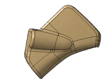
Class B surface:
Class A surface is offset for a distance of 2.5mm. The are voids created after offset, which need to be filled/recreated by usinfgthe proper surface tools.
 |
| Class B Surface. |
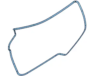
Class C surface:
Using the Sweep of 3 degrees along the tooling axis or 90 degrees with reference to surface is used and Class C surface is created.
 |
| Class C Surface. |
Surface body:
First the Class A & C surface are joined together and then trimmed with Class B surface.
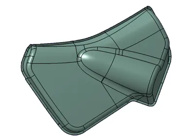 |
|
| Class A & C surface joined. | Class A & C trimmed with B surface |
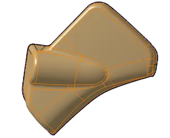
Solid Component:
The surface body created is converted to solid component using the 'Close Surface' option.
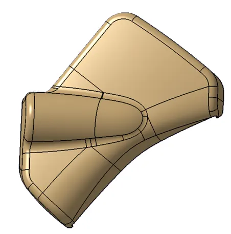 |
| Bottom Map pocket Surface body |
B-side features:
Flanges are provided with clearance, where the heat stake from the adjacent component are placed and heat staking is performed. The surface should be flat where the heat staking is performed(shown in below figure). Rib pattern are created for extra strength of the component.
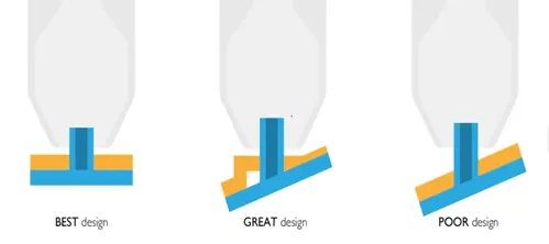 |
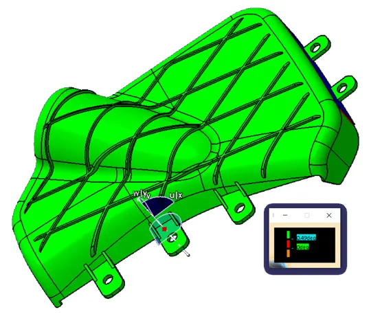 |
| Surface conditions for heat staking process. | Ribs and flanges are satisfy draft condition of 0.5 degrees. |
Draft analysis on Final Solid component.
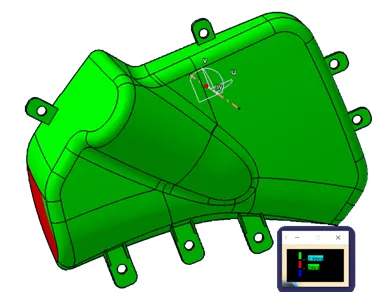
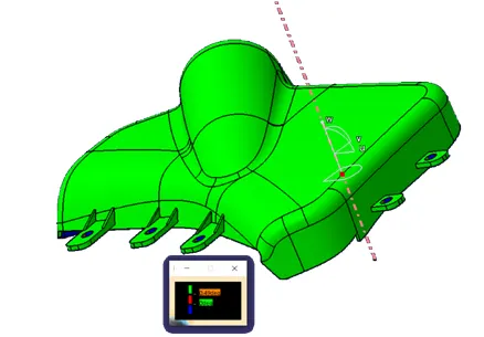
Solid component satisfies the draft condition of 3(2.9) degrees and the B-side features satisfies at 0.5 (0.49) degrees of draft angle as shown in below figure.
 |
|
| Draft analysis for solid component (3 degrees) | Draft analysis for B-side features (0.5 degrees) |
ARM REST:
Class B surface:
Class A surface is offset for a distance of 2.5mm. The are voids created after offset, which need to be filled/recreated by usinfgthe proper surface tools.
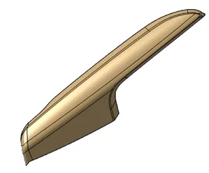 |
| Class B Surface. |
Class C surface:
Using the Sweep of 3 degrees along the tooling axis or 90 degrees with reference to surface is used and Class C surface is created.
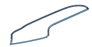 |
| Class C Surface. |
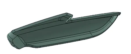
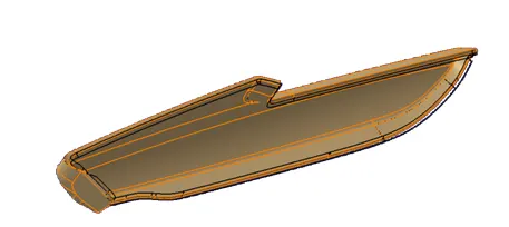
Surface body:
First the Class A & C surface are joined together and then trimmed with Class B surface.
 |
|
| Class A & C surface joined. | Class A & C trimmed with B surface |
Solid Component:
The surface body created is converted to solid component using the 'Close Surface' option.
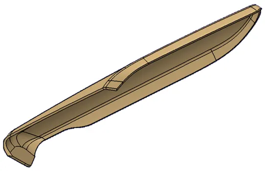 |
| Arm Rest Surface body |
B-side features:
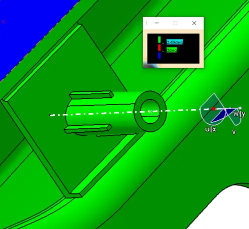
Heat stakes are created on the flat surface for attaching the arm rest with the adjacent component and ribs are provided for better strength.
 |
|
| Heat stake along with flange satisfy the draft condition of 0.5 degrees. | Ribs satisfy the draft condition of 0.5 degrees. |

Draft analysis on Final Solid component.
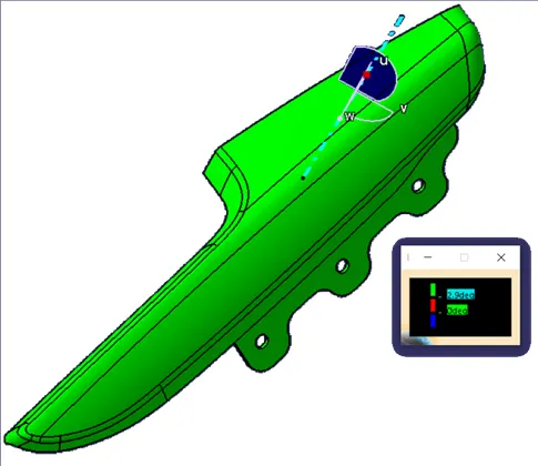
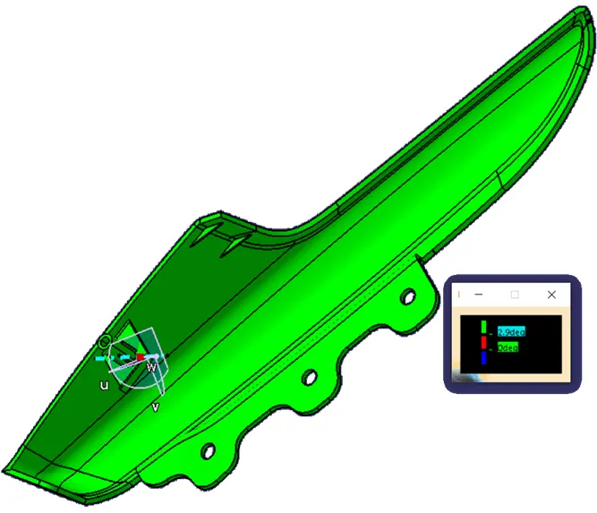
Solid component satisfies the draft condition of 3(2.9) degrees and the B-side features satisfies at 0.5 (0.49) degrees of draft angle as shown in below figure.
 |
|
| Draft analysis for solid component (3 degrees) | |
SWITCH BEZEL:
Class B surface:
Class A surface is offset for a distance of 2.5mm. The are voids created after offset, which need to be filled/recreated by usinfgthe proper surface tools.
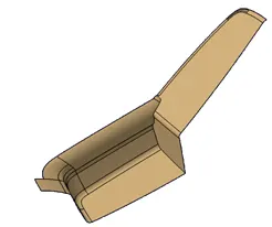 |
| Class B Surface. |
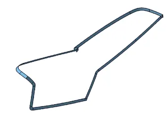
Class C surface:
Using the Sweep of 3 degrees along the tooling axis or 90 degrees with reference to surface is used and Class C surface is created.
 |
| Class C Surface. |
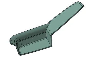
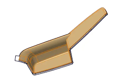
Surface body:
First the Class A & C surface are joined together and then trimmed with Class B surface.
 |
|
| Class A & C surface joined. | Class A & C trimmed with B surface |
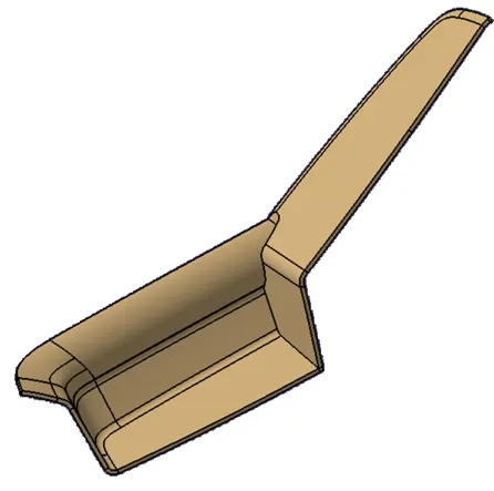
Solid Component:
The surface body created is converted to solid component using the 'Close Surface' option.
 |
| Switch Bezel Surface body |
B-side features:
| |
|
| Heat stake along with flange satisfy the draft condition of 0.5 degrees. | Ribs satisfy the draft condition of 0.5 degrees. |
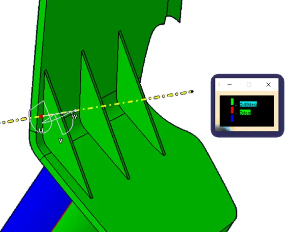
Draft analysis on Final Solid component.
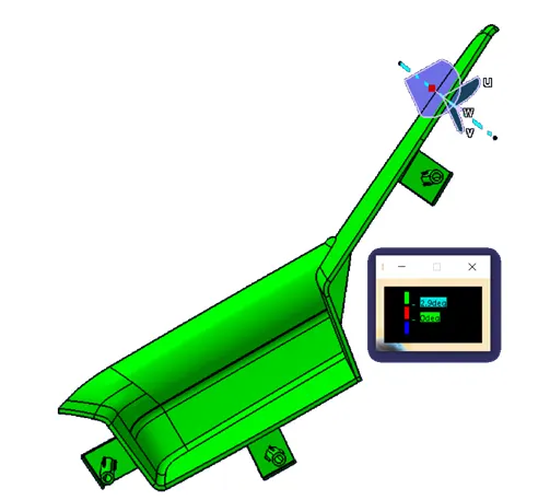
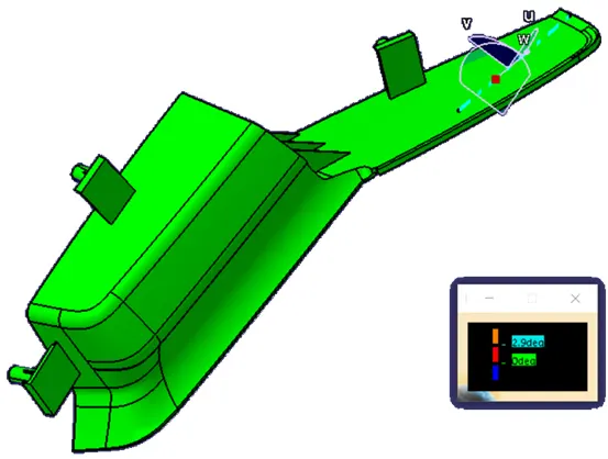
Solid component satisfies the draft condition of 3(2.9) degrees and the B-side features satisfies at 0.5 (0.49) degrees of draft angle as shown in below figure.
 |
|
| Draft analysis for solid component (3 degrees) | |
PUSH CLIPS:
An engineering feature which helps the door trim panel to be in contact with the sheet metal part of the door panel. Since this is made up of rubber so no specific rules are followed it is just created according to the given input which is shown below.
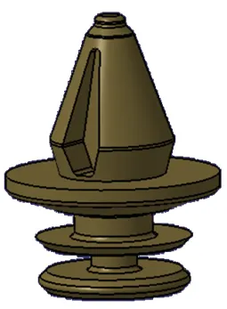 |
| Push clip |
DOOR TRIM PANEL:
Finally, the panel is rendered in CATIA.
|
|
| DOOR PANEL FRONT SIDE |
|
|
| DOOR PANEL REAR SIDE |
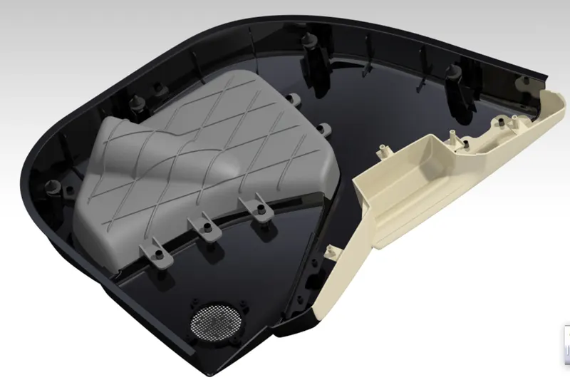
Conclusion:
Plastic component from given Class-A surface & master section.
Doghouse, Heatstakes, Doghouses & Screwbosses are created for attachment of the components.
Draft analysis is performed on Class-A surface, B-side features & on plastic components individually.