Week 8 - Challenge 3 - Switch Bezel Design
AIM: Creating the Switch Bezel Plastic component through the given Class-A surface and performing Draft Analysis on both solid component and Class A-Surface.
DESCRIPTION:
Draft Analysis:
Draft is the angle in which the part is tapered for easy ejection from core and cavity block.
Draft analysis is a technique used to analyze whether the drafted CAD model is manufacturable with the given draft conditions. Tooling axis (the direction in which the mold is ejected) is provided, so that there should be a smooth ejection of the surface/part from Core-Cavity block.
A. Steps involved in creating TOOLING AXIS:
1. Extract a surface and create a point on that surface.
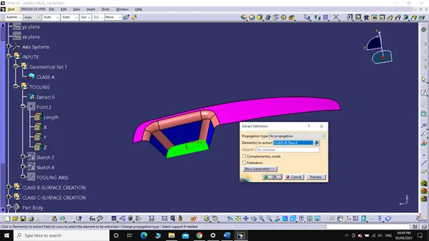
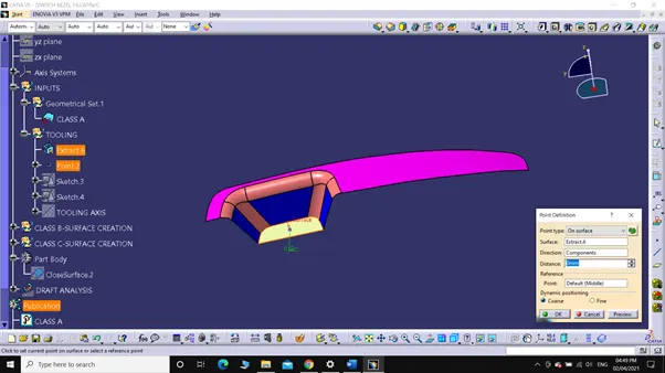
2. Create axis system on the point.
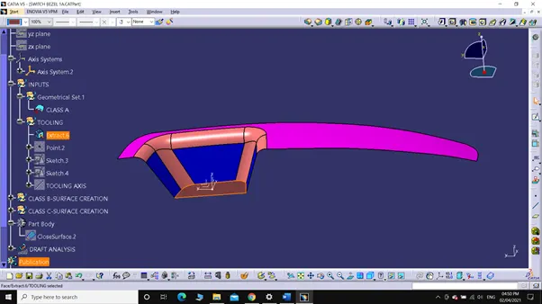
3. Create sketch on YZ-plane and using bisection of lines we get Tooling axis clearing Y-Direction.
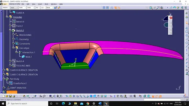
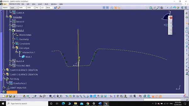
4. Create sketch on XZ-plane and draw a line at an angle of 5 degree with the line created on the 3D intersection projection, this is our Tooling axis clearing Y-Direction.
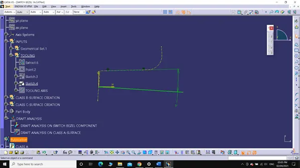
5. Now, create a bisecting line using the Clearing axis and a point.
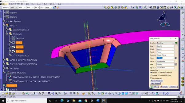
This bisecting line will be our Tooling axis for Switch Bezel.
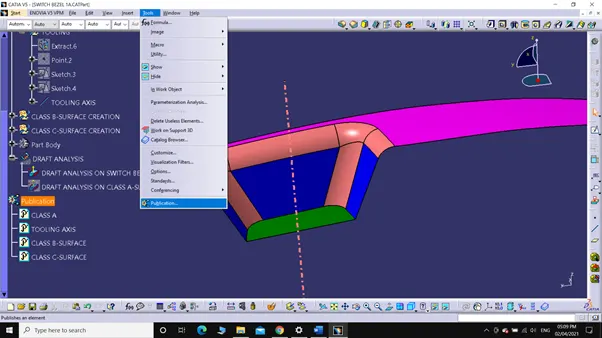
6. Publish Tooling axis and Class A surface of Switch Bezel for easy selection.

B. Steps involved in creation of Class B-SURFACE:
1. Extract the simple surfaces (which don’t have fillet) and then untrim the extracted surfaces.
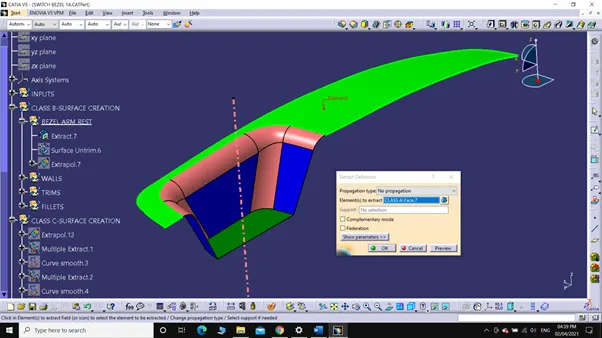
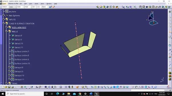
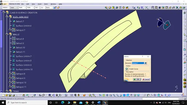
2. Extrapolate and trim the surface as per requirement.
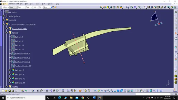
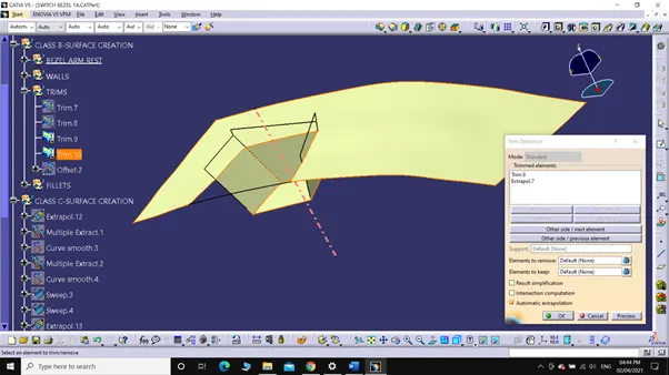
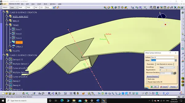
3. Offset the trimmed part to a distance of 2.5mm.
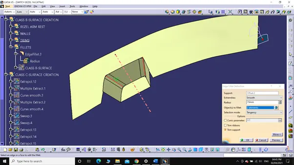
4. Now perform the fillets at the edges.
The fillet radius is chosen in such a way that there should be equal thickness at the curved surface.
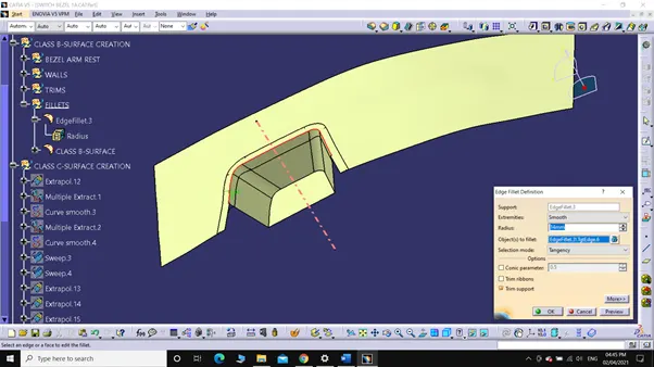
5. After completion of the fillet the surface we get is CLASS-B SURFACE.
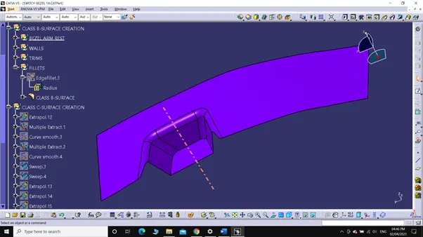
C. Steps involved in creation of C-SURFACE.
1. Extract the OUTER boundary of the class A-surface and apply smooth curve separately to the boundaries.
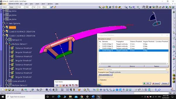
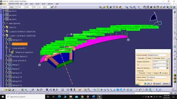
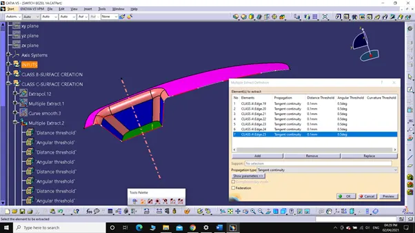
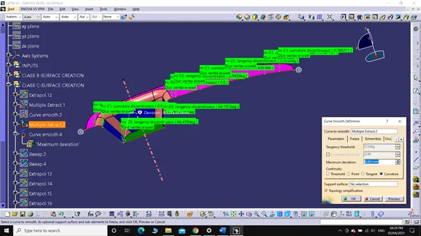
2. Sweep the boundaries along the TOOLING AXIS separately.
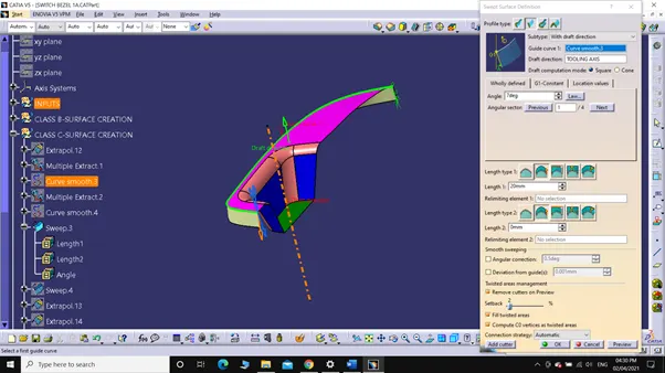
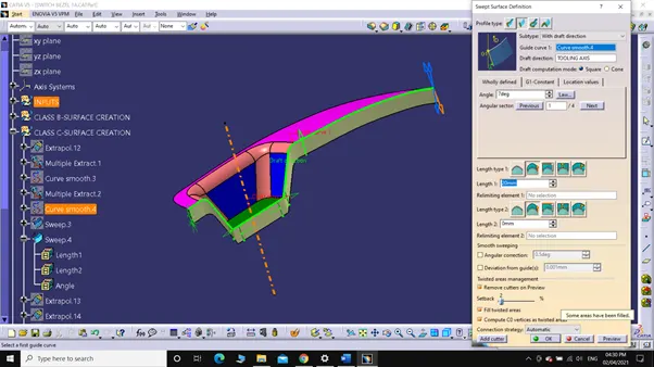
3. Extrapolate the two surfaces which were swept along tooling axis and trim the extra part.
Then extrapolate the CLASS A-Surface and finally trim extra part and closed surface is obtained.
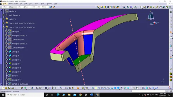
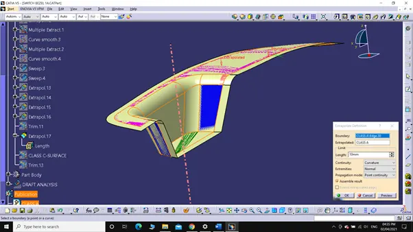
4. Trimming the extrapolate Class A-surface with the timed surface we get Class C-SURFACE.
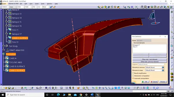
D. Steps involved in creating PLASTIC COMPONENT:
1. Trim CLASS C-SURFACE with CLASS B-SURFACE.
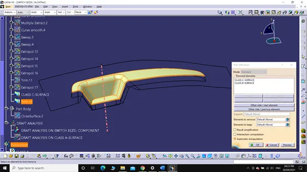
2. Now, we have a hollow surface of Base BRACKET which need to be filled with plastic.
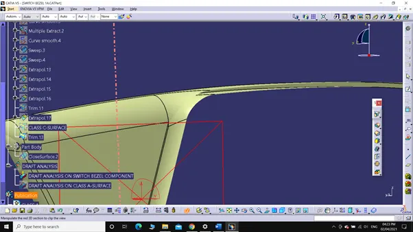
3. Change the window to ‘PART DESIGN’ and using ‘CLOSE SURFACE’ turn it to a solid part.
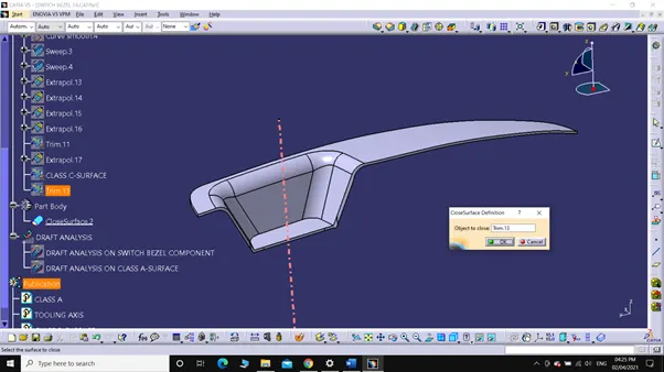
E. Steps involved in DRAFT ANALYSIS ON AWITCH BEZEL COMPONENT:
1. Select 'Customize view parameters' from the 'View mode' and choose 'Materials'.
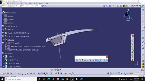
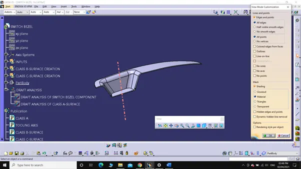
2. Select 'Feature Draft Analysis' from the 'Analysis toolbar'.
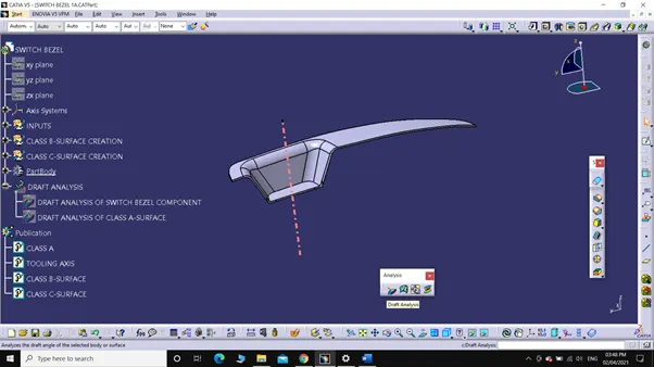
3. Now, holding the red-dot, which is on the compass (present on Top-right corner of the window) align with the Tooling axis and lock it.
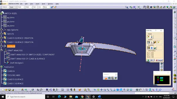
4. Set the Minimum draft angle (3 degree for plastic components) in 'Draft Analysis.1' dialog box.
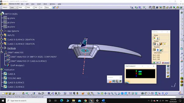
5. Choose 'Fan Cover' as element in 'Draft Analysis' dialog box or Just click on the surface.
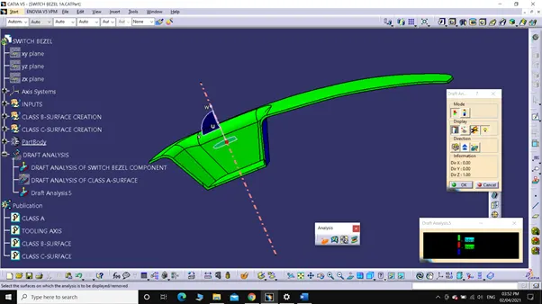
6. After selecting if the color changes to,
a. Green, then the draft of the Part has minimum draft angle of 3 degree.
b. Red, then the draft angle of the part lies between 0-3 degree.
c. Blue, then the draft angle of the part is less than 0 degree.
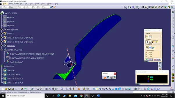
7. By choosing 'Analyse under running point' from 'Analysis toolbar' we can check the draft angle at any point on the surface just by moving the pin.
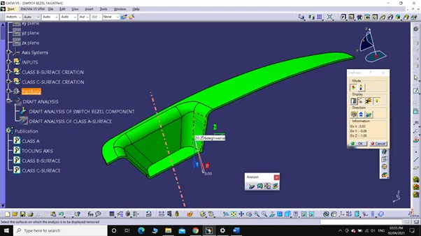
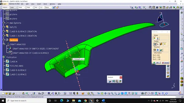
E. Steps involved in DRAFT ANALYSIS ON CLASS A-SURFACE:
1. Select 'Customize view parameters' from the 'View mode' and choose 'Materials'.
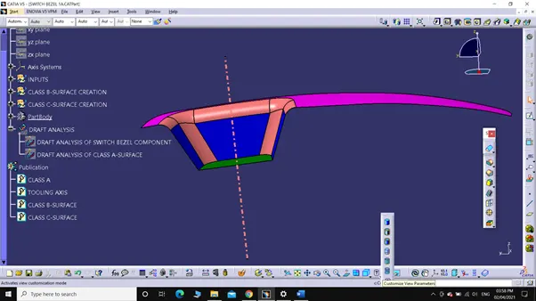
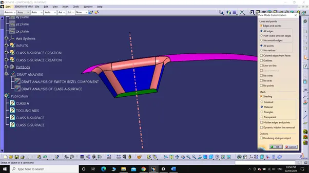
2. Select 'Feature Draft Analysis' from the 'Analysis toolbar'.
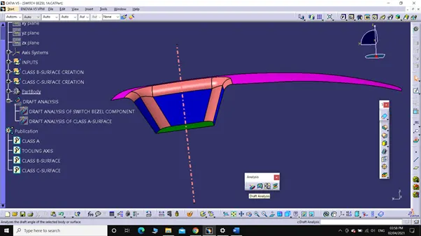
3. Now, holding the red-dot, which is on the compass (present on Top-right corner of the window) align with the Tooling axis and lock it.
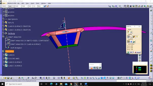
4. Set the Minimum draft angle (3 degree for plastic components) in 'Draft Analysis.5' dialog box.
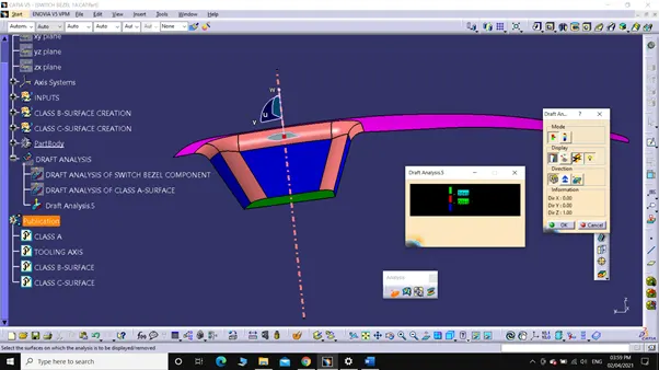
5. Choose 'Switch Bezel component' as element in 'Draft Analysis' dialog box or Just click on the surface.
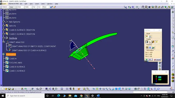
6. After selecting if the color changes to,
a. Green, then the draft of the Part has minimum draft angle of 3 degree.
b. Red, then the draft angle of the part lies between 0-3 degree.
c. Blue, then the draft angle of the part is less than 0 degree.
7. By choosing 'Analyse under running point' from 'Analysis toolbar' we can check the draft angle at any point on the surface just by moving the pin.
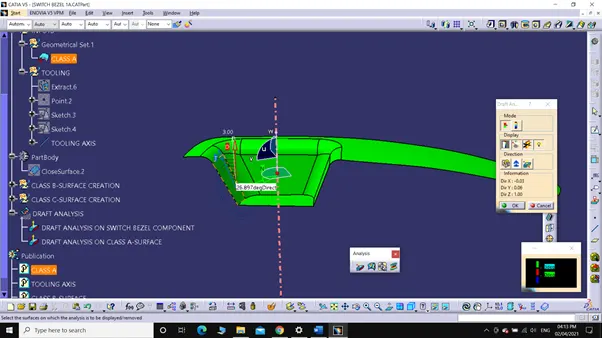
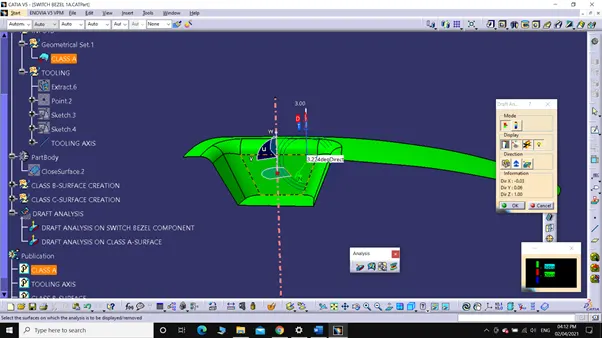
F. Screenshots in different views:
1. Isometric View:
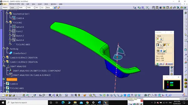
2. Front View:
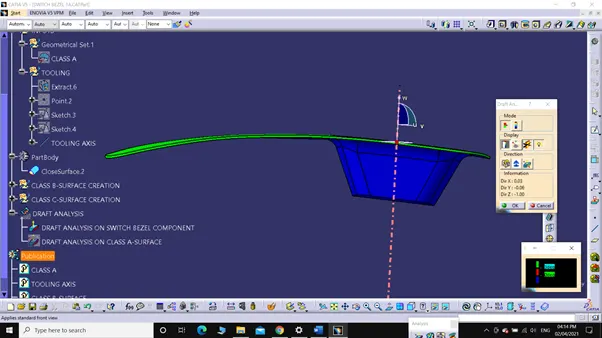
3. Right View:
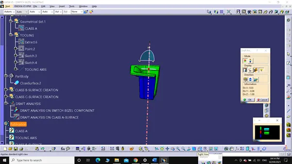
4. Left View:
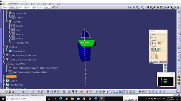
5. Top View:
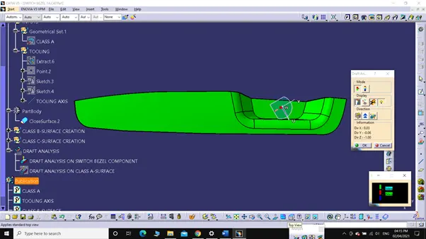
G. Screenshot of CLASS A, B, C-SURFACES.
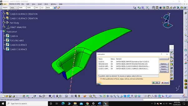
CONCLUSION:
Switch Bezel CATpart is created using 'CLASS A-SURFACE' and converted to a solid part using 'CLOSE SURFACE'. Draft analysis is performed on both solid component and Class A-surface.