Door Arm Rest Week 8 Challenge
Aim: Creation of Door Arm rest using the given CLASS A-SURFACE and converting it to a solid component and to perform draft analysis on both.
Description:
A. Steps involved in creation of Tooling Axis:
Since this is a quite complex design the whole component cannot be cleared using single tooling axis, so I have created two tooling axes.
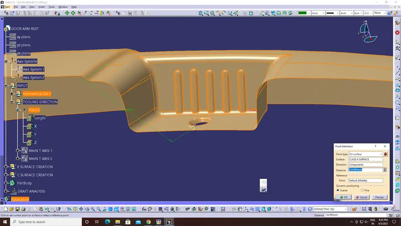
1. Create an Axis system on the surface of CLASS A-SURFACE as shown in figure.
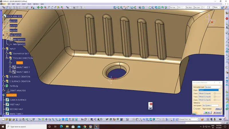
2. Create an axis system on the point created.
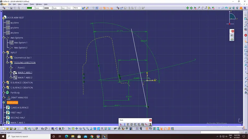
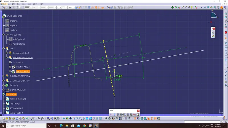
3. Lines are traced from the 3D intersect option by creating a sketch on YZ-plane on the new axis system which was created.
A bisecting line is created in between these two lines. Finally, using that line a line is created at 3 degree angle, which is our tooling axis for one direction.
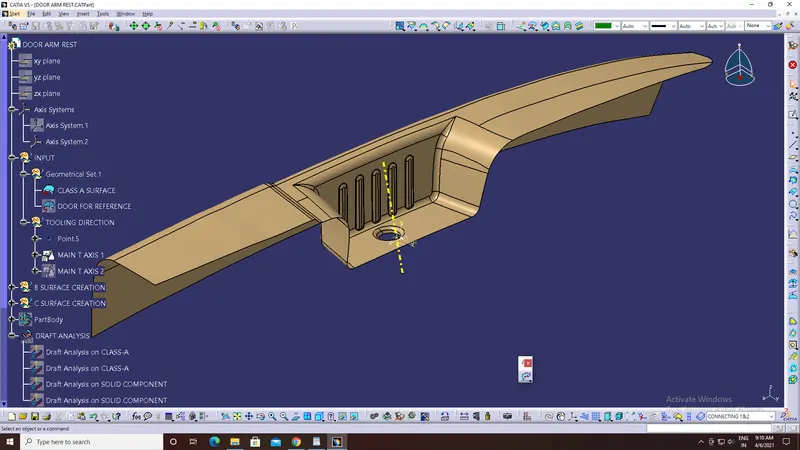
4. Lines are traced from the 3D intersect option by creating a sketch on XZ-plane on the new axis system which was created.
A random line is created(blue colored line) at some angle. Then, a part of line is traced using the 3D intersect option and using the bisecting line option a new line (white colore) is created which is our tooling axis for other direction.
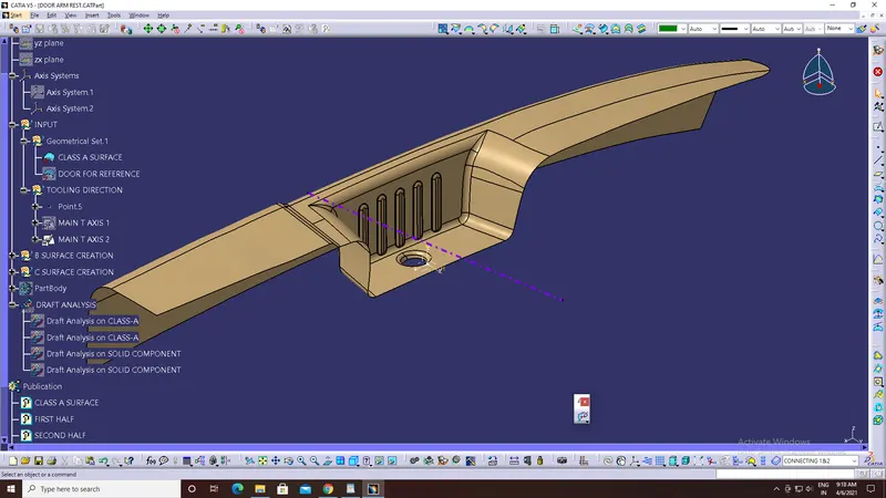
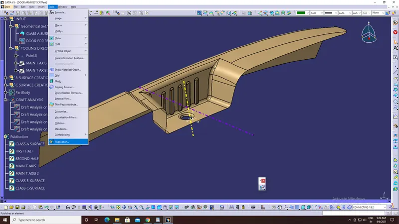
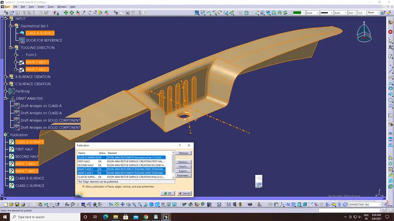
5. Publication of Tooling axes and Class A surface of Door arm rest is done for easy selection.
B. Steps involved in creation of Class B-SURFACE:
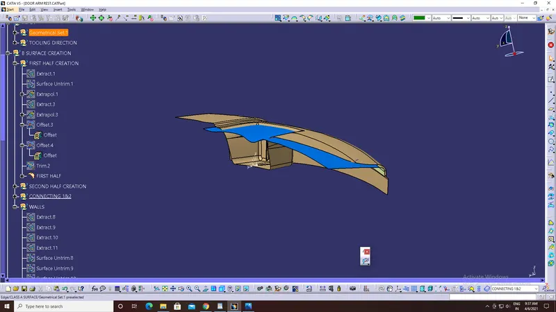
Creation of First half:
1. Extract the simple surfaces (which don’t have fillet) and then untrim the extracted surfaces.
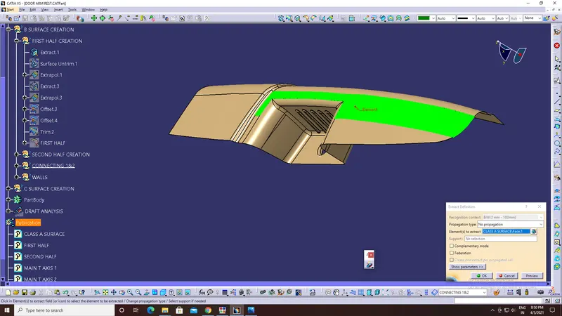
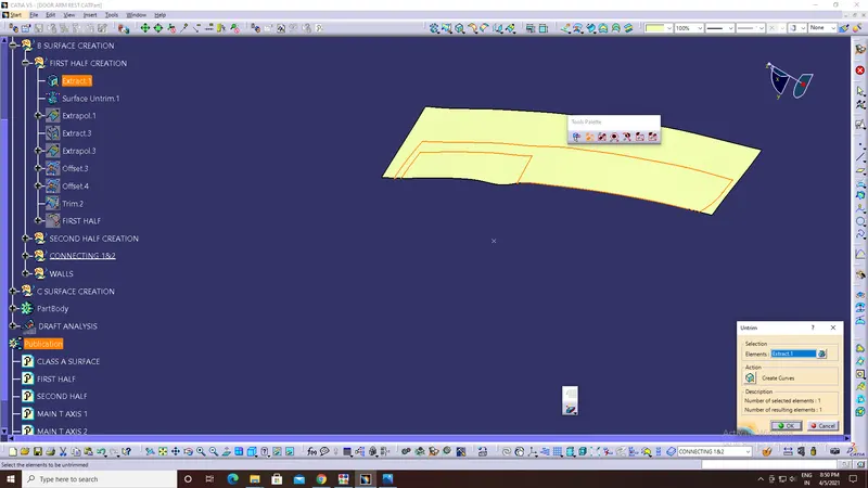
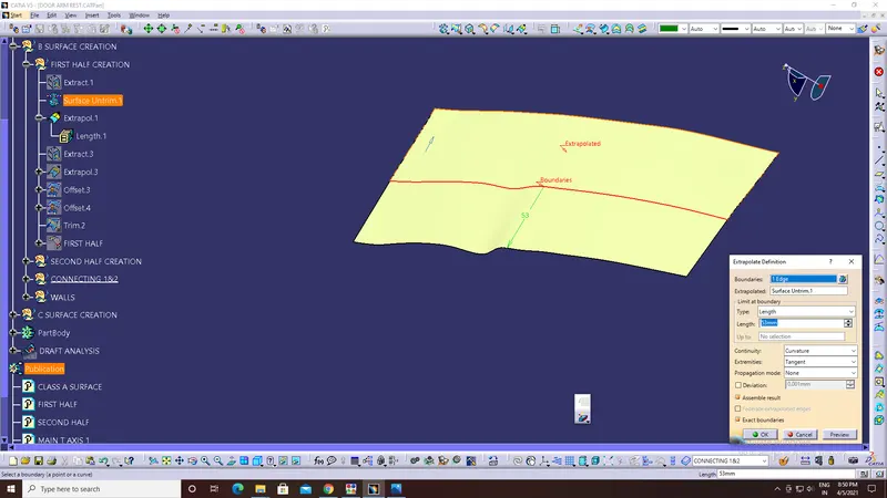
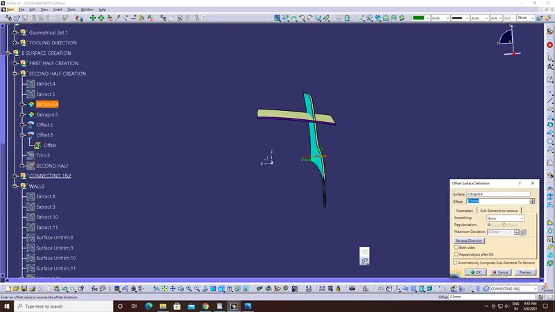
2. Extrapolate and trim the surface as per requirement and offset it to a distance of 2.5mm. The colored surfaces are offset to 2.5mm distance.
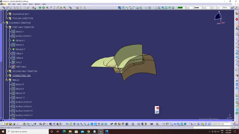
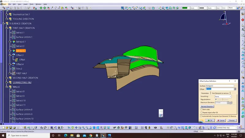
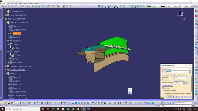
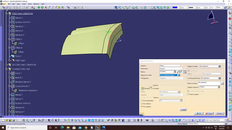
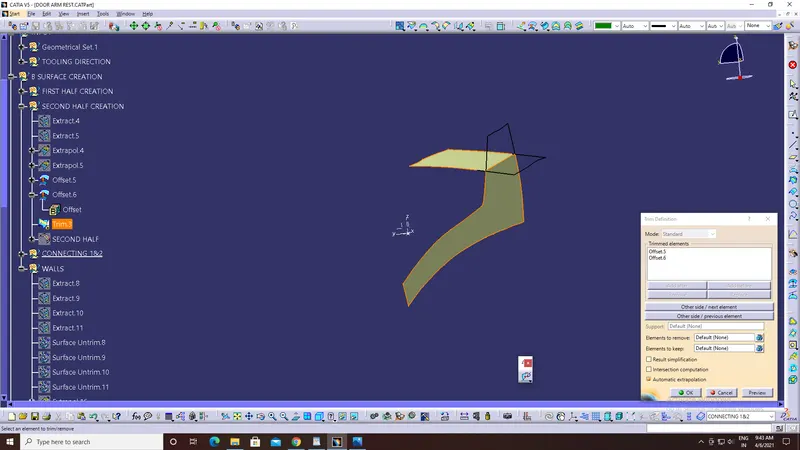
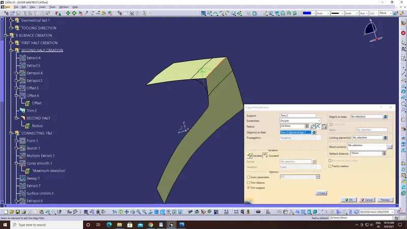
3. Trim the extra portion from the offset surface and fillet the sharp edge so as get the proper shape.
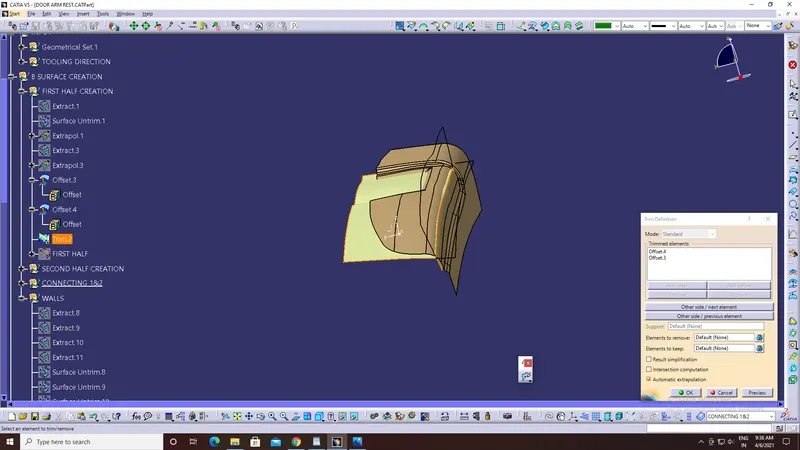
NOTE: If the fillet is to be given to the surface which is at inner side of the Class A-Surface, Outer fillet radius - Thichness.
If the fillet is to be given to the surface which is at outer side of the Class A-Surface, Outer fillet radius + Thichness.
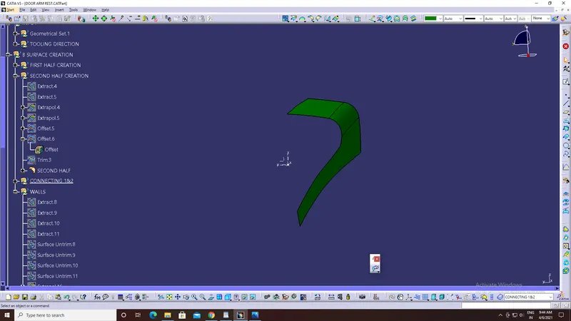
4. After trimming we get the first half surface.
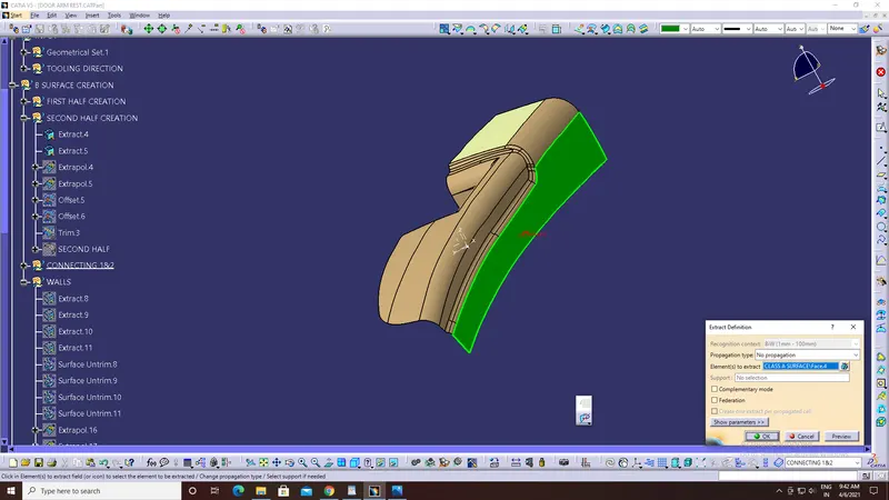
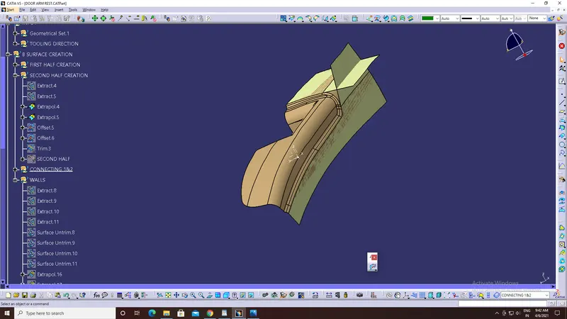
Creation of Second half:
Same steps which were followed while creation first half are followed here and we get the following result.
Creation of the curved surface:
1. Create a point on Class A-Surface as shown in below picture and insert an axis system on that point.
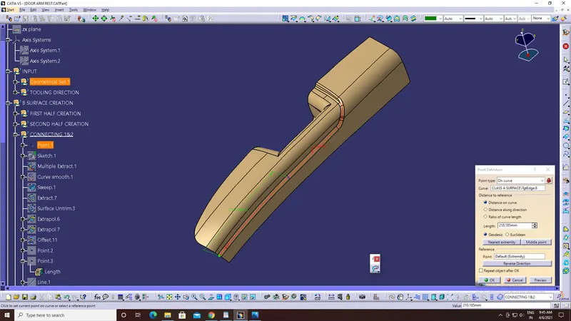
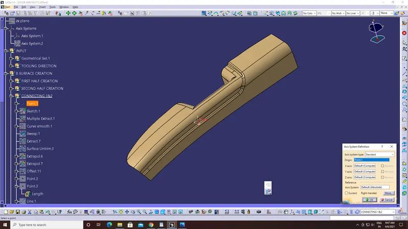
2. Create a sketch on YZ-Plane on newly created axis and trace the curves of Class A-Surface using the 3D intersect option.
Draw a line which tangent to the curved curve as shown in below picture.
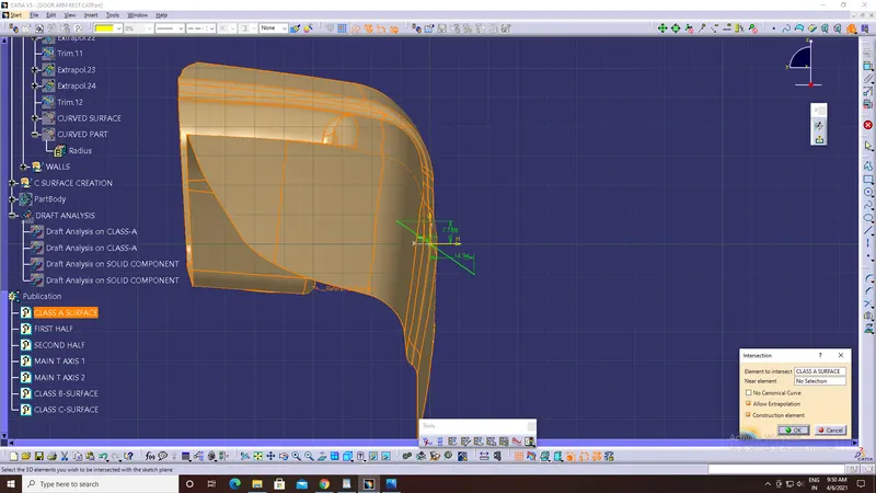
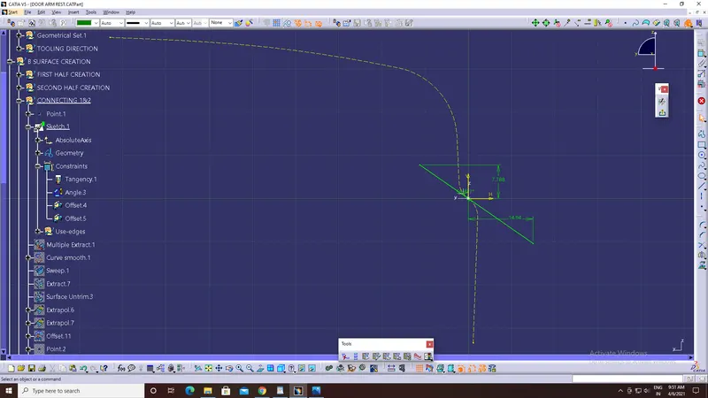

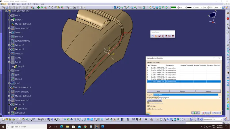
3. Using multiple extract, ectract the curve line and smooth the curve.
Then, sweep the above drawn sketch along the extracted curve using 'With refrence surface' as subtype from the "Swept surface definition" dialog box.
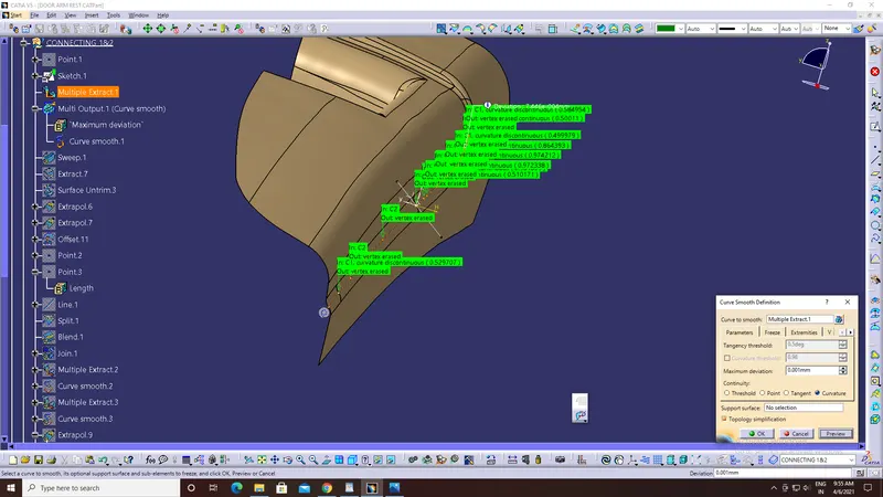
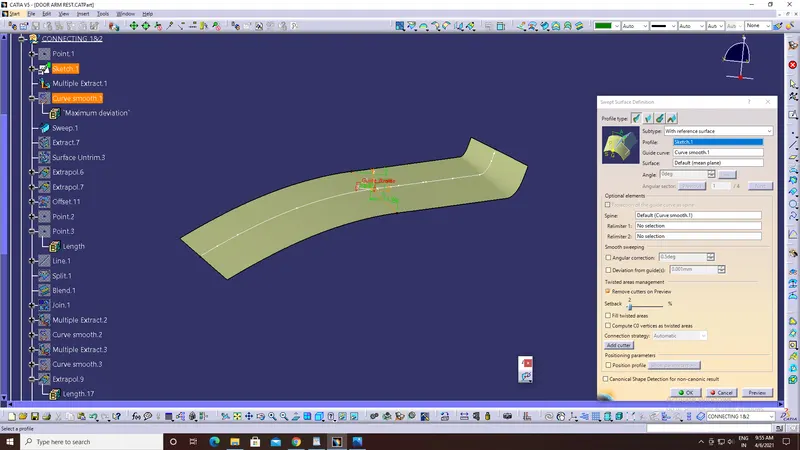
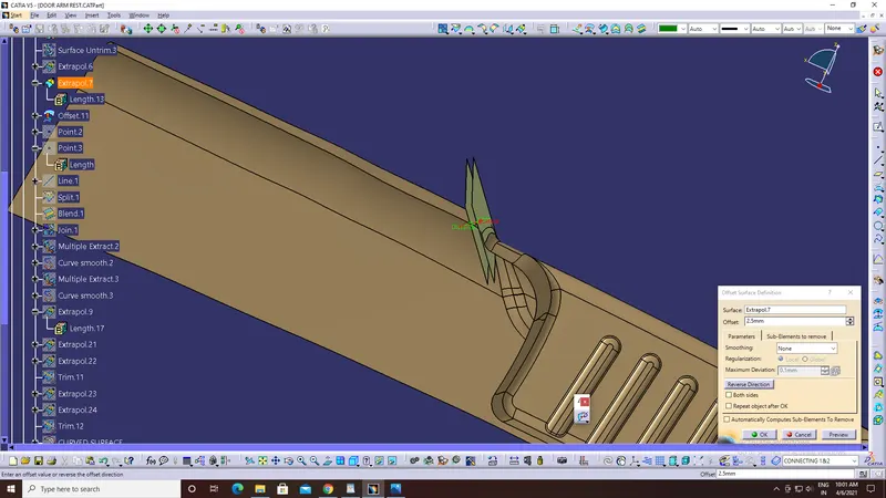
4. Extract the other part untrim it, extrapolate and offset it.
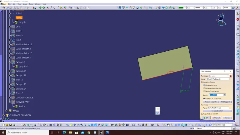
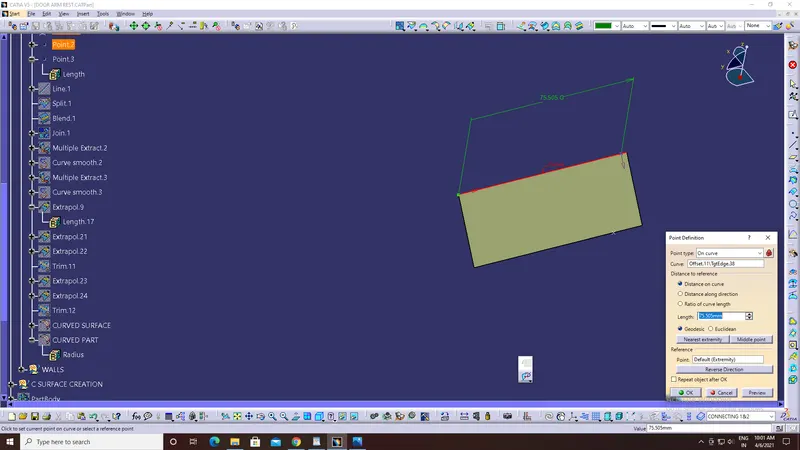
Then, create two points on the edges of the offset surface as shown in below pictures. Create a line using these two points and split the surface using the line.

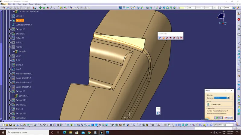
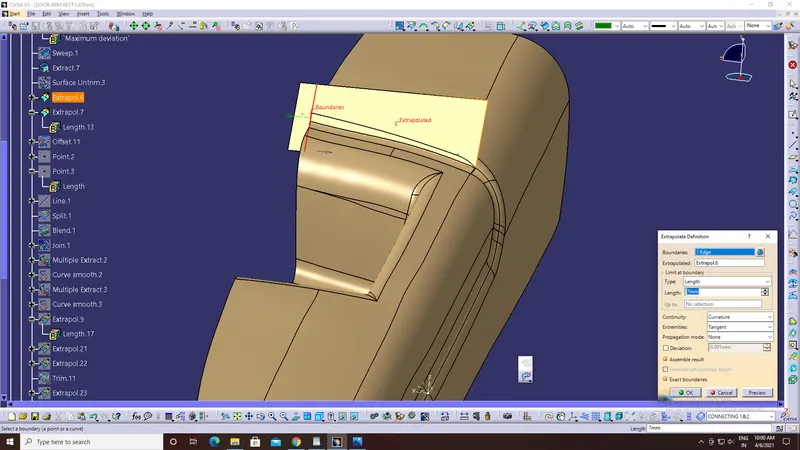
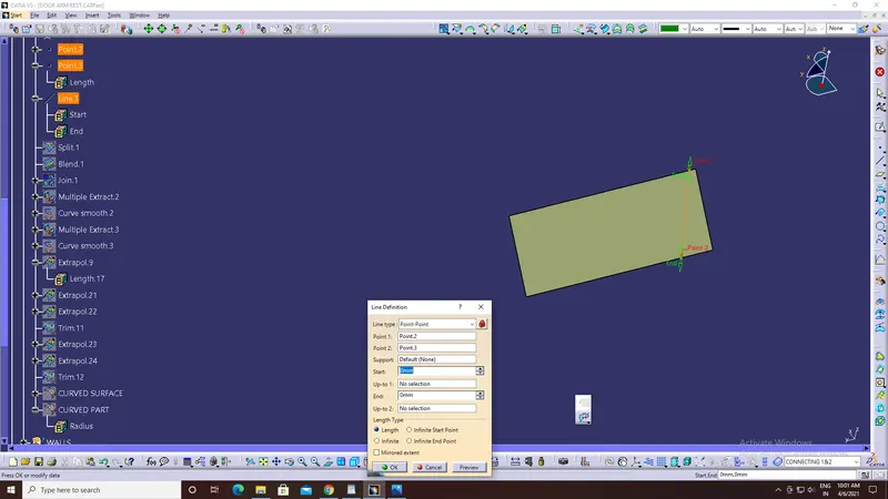
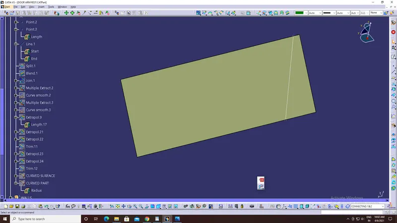
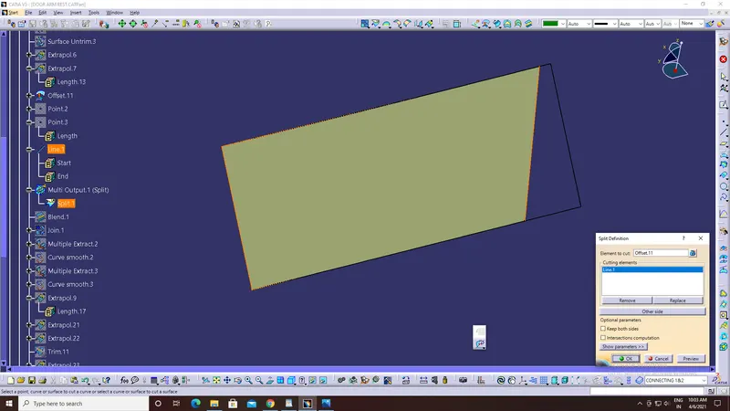
5. The line which is created on the surface is done so that we can get a smooth blend. Using the two surface we create a blend. Then join all the components.
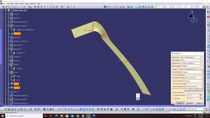
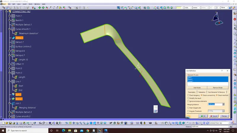
6. Extrapolate the joined surface, First half and second half. Trim the Join surface with first half and trim the obtained trim part with the second half and we get the following results.
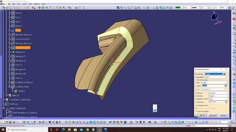
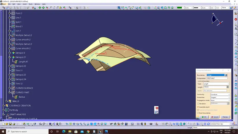
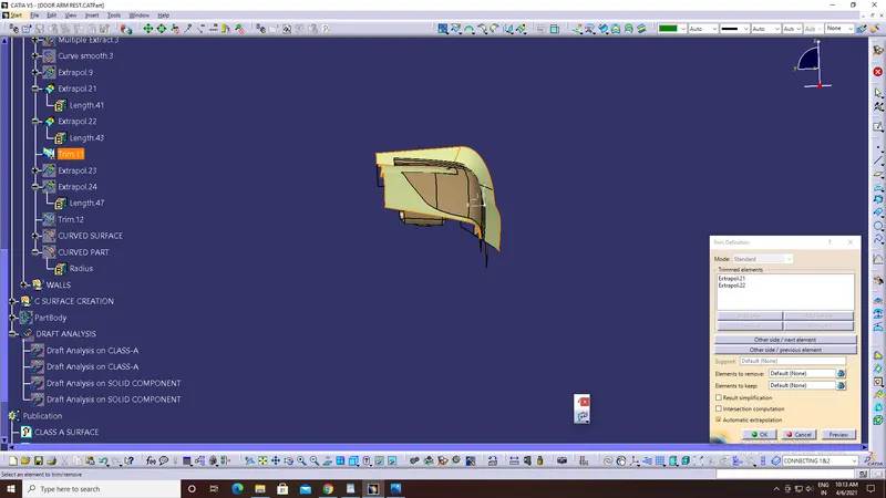
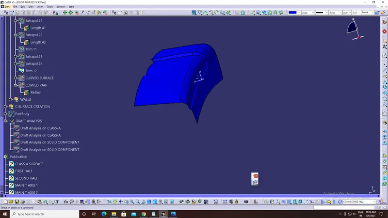
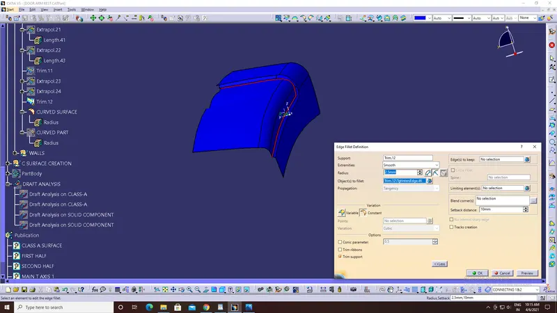
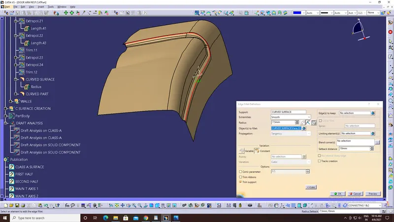
7. Fillet is applied at the edges.
NOTE: If the fillet is to be given to the surface which is at inner side of the Class A-Surface, Outer fillet radius - Thichness.
If the fillet is to be given to the surface which is at outer side of the Class A-Surface, Outer fillet radius + Thichness.
Creation of walls:
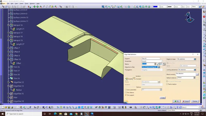
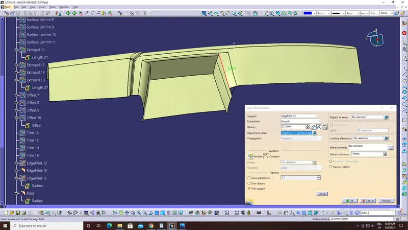
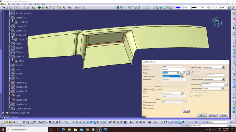
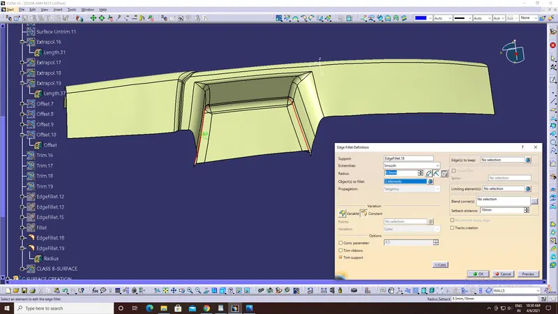
1. Extract, Untrim , extrapolate, offset the walls and trim them with the curved curve created.
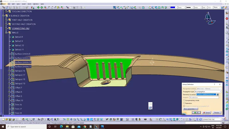
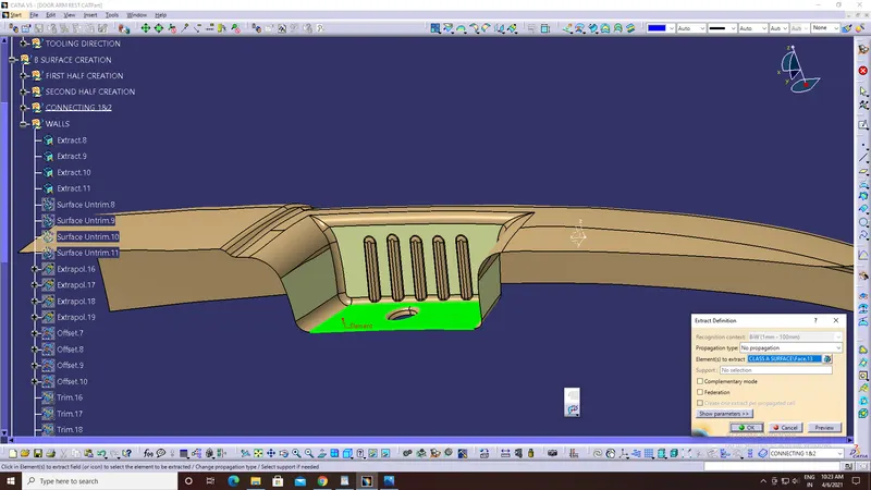
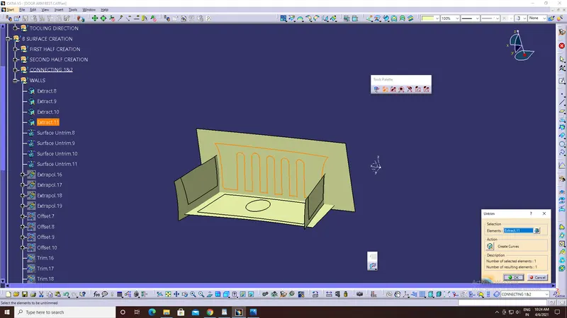
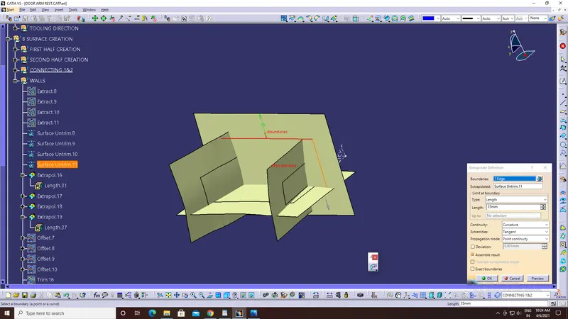
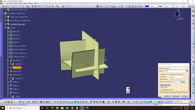
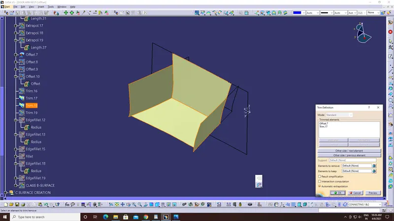
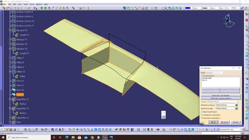
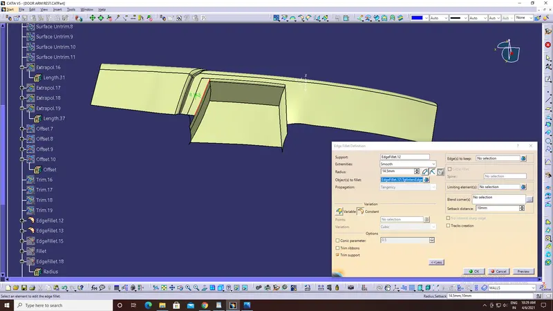
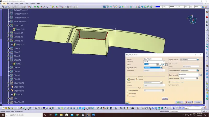
2. Fillet the sharp edges accordingly. Class B-Surface is Created.
C. CLASS B-SURFACE in different views:
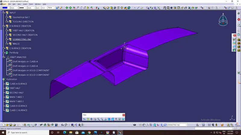
1. Isometric view:
2. Front View:
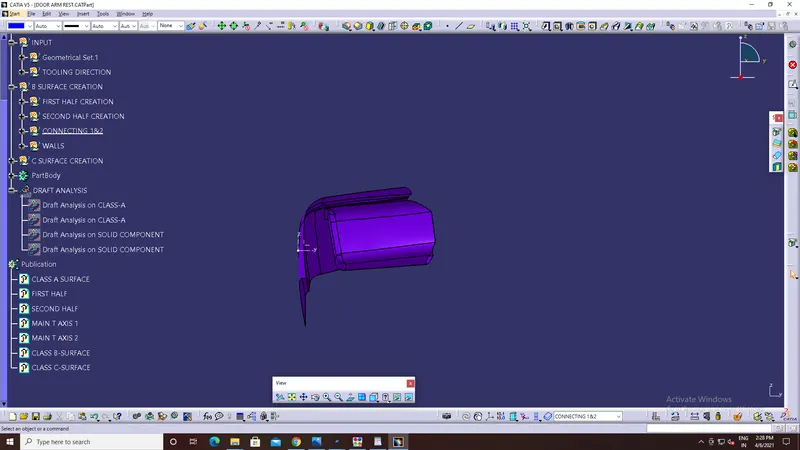
3. Right View:
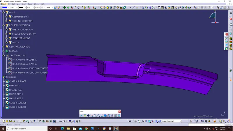
4. Left View:
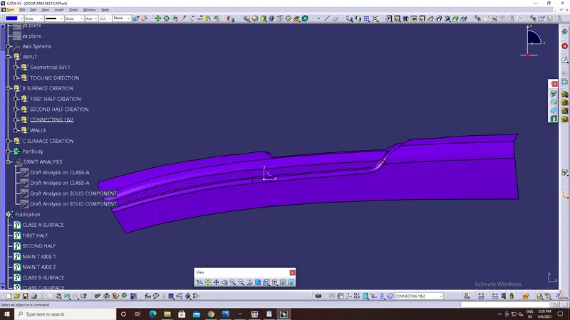
5. Top View:
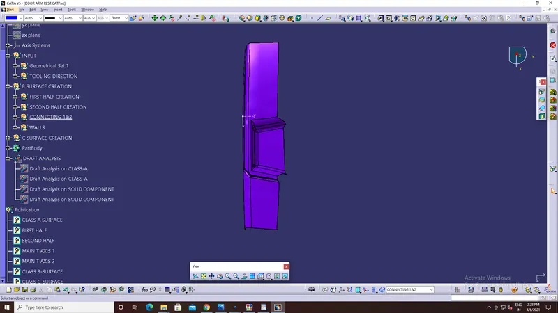
D. STEPS INVOLVED IN CREATION OF CLASS-C SURFACE:
1. Extract the flat and simple curves from the Class A-Surface, and turn them to smooth curve and sweep along the tooling axis by selecting "With draft direction" as subtype in "Swept surface definition" dialog box.
Tooling axes are selected as per requirement.
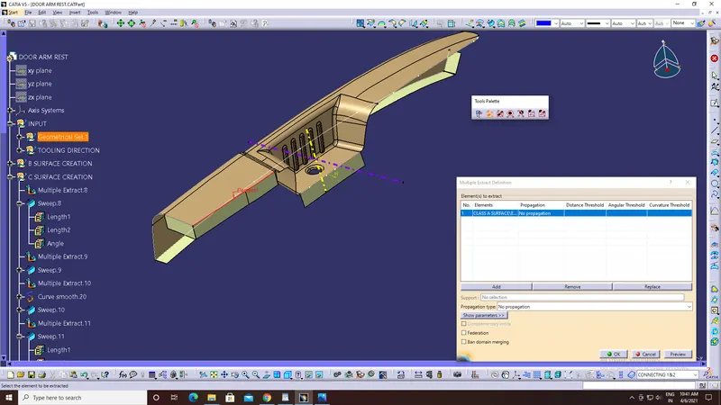
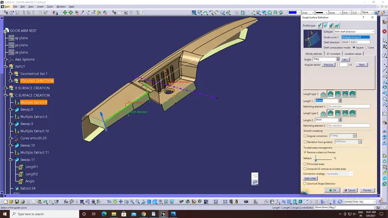
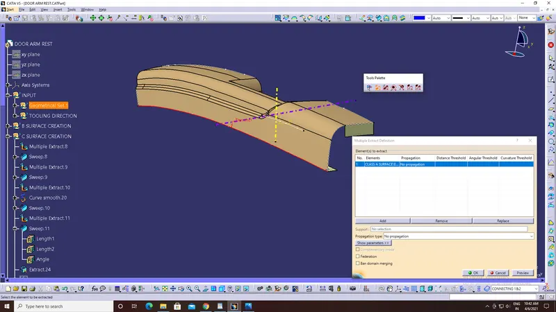
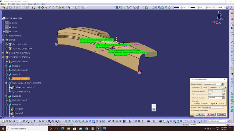
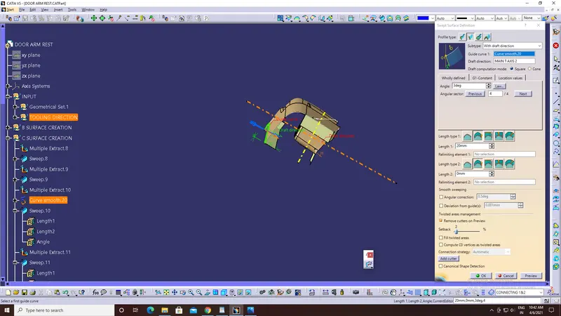
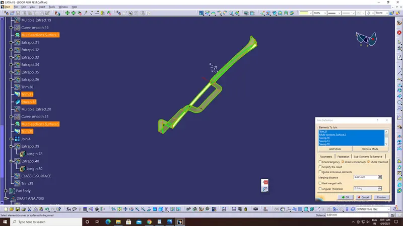
2. At the curve edges the surfaces are created using Multi Section Surface.
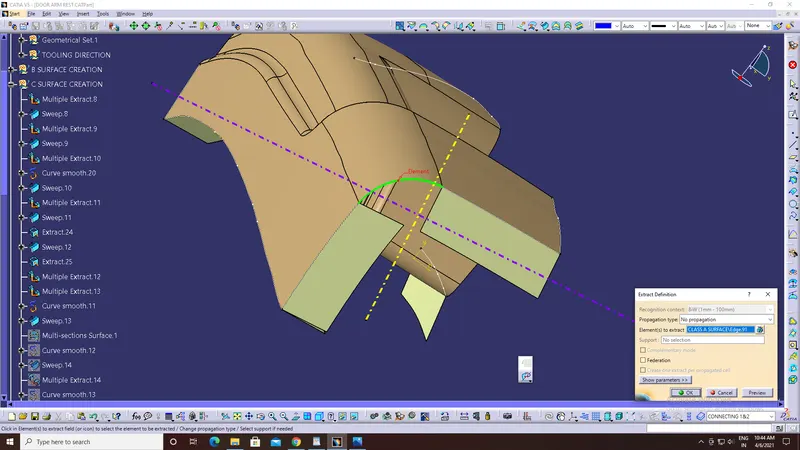
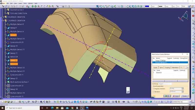
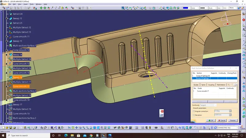
3. Extrapolate at corners because of the gap created and trim the extra portion. Then, join all the portions.
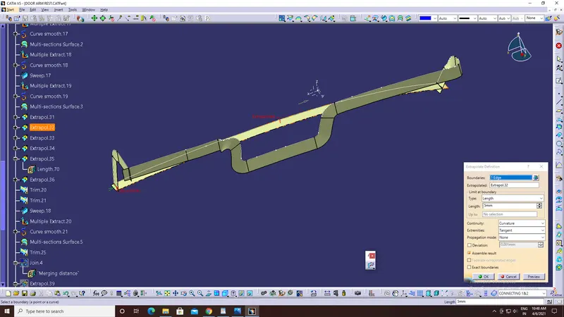
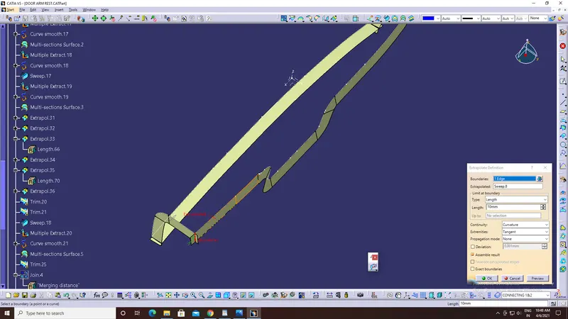
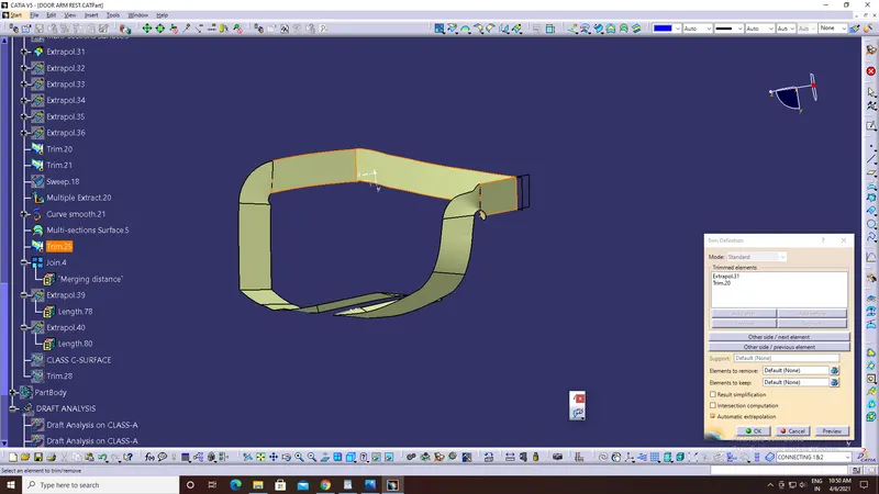
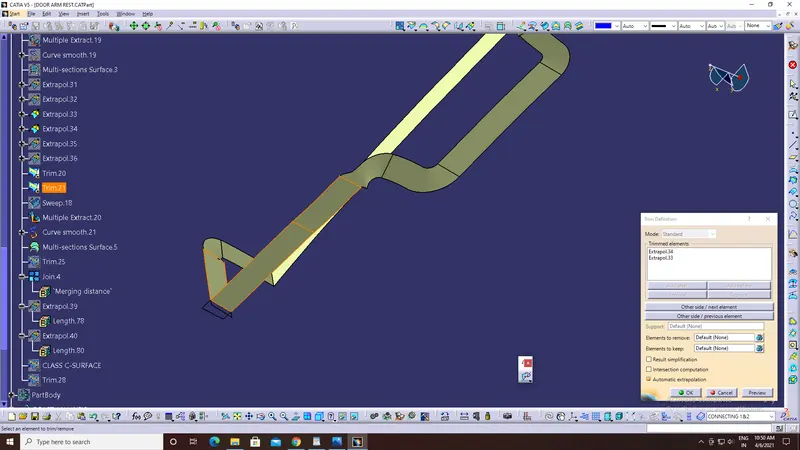
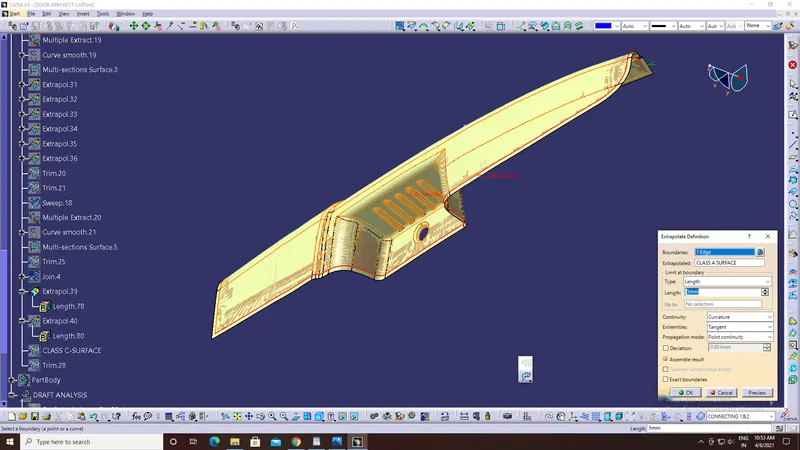
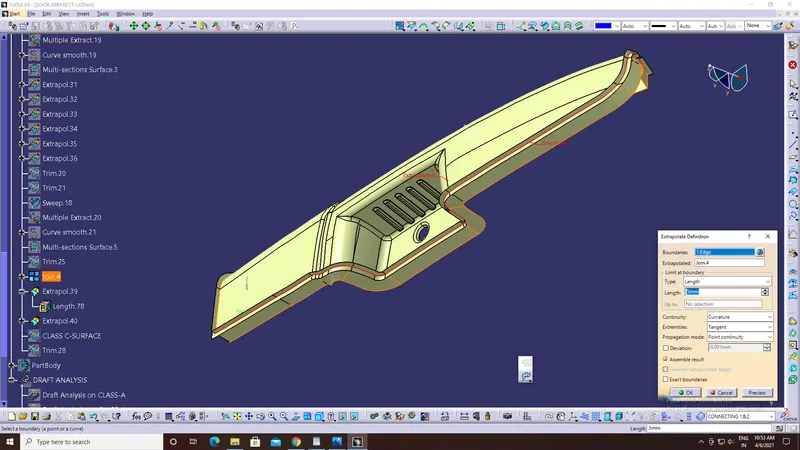
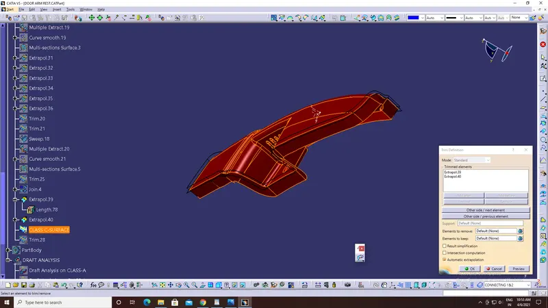
4. Extrapolate the CLASS A-SURFACE and the Join component and trim the extra portion, so that there should not be any gap.
E. CLASS C-SURFACE in different views:
1. Isometric View:
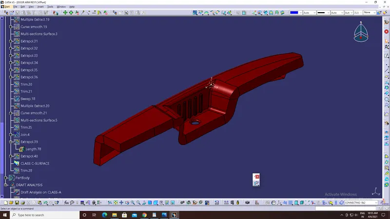
2. Front View:
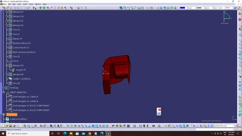
3. Right View:
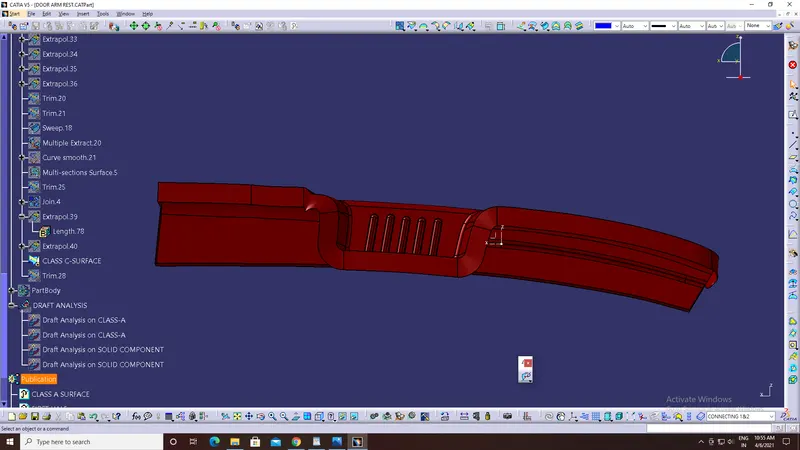
4. Left View:
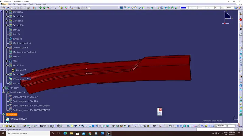
5. Top View:
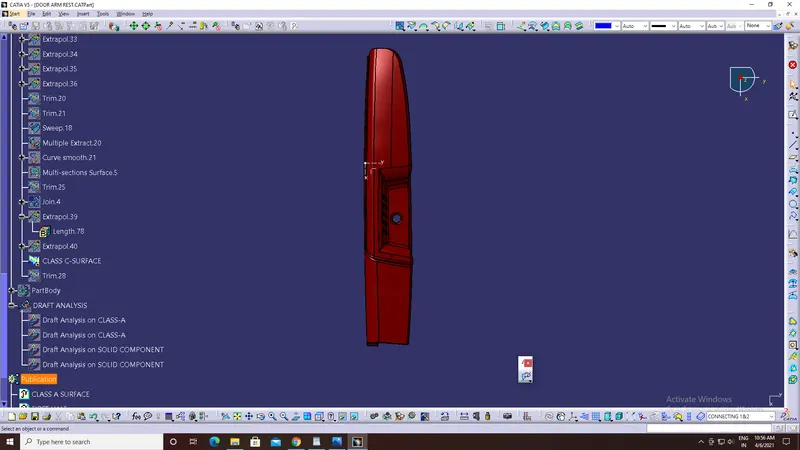
F. Creation of Solid component:
1. Trim Class C-Surface with Class B-Surface.
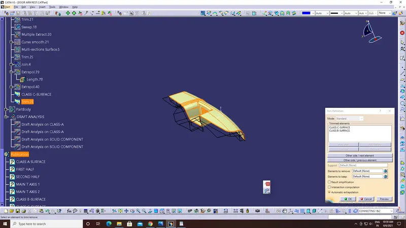
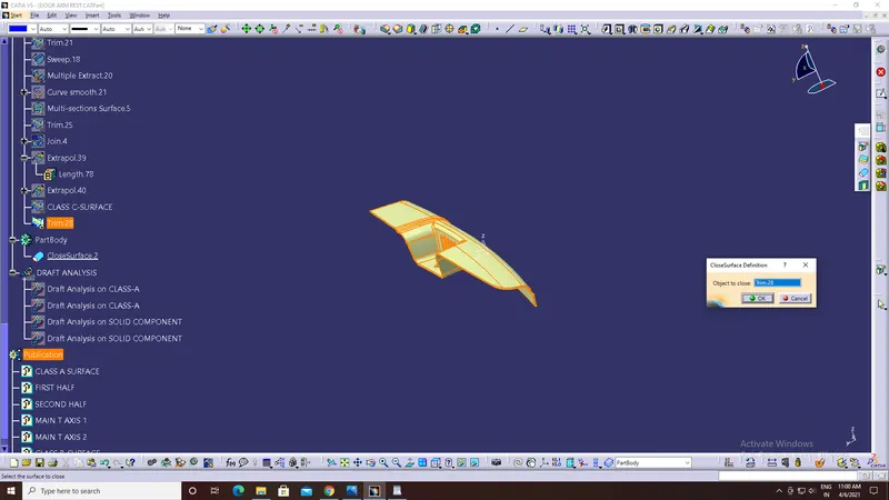
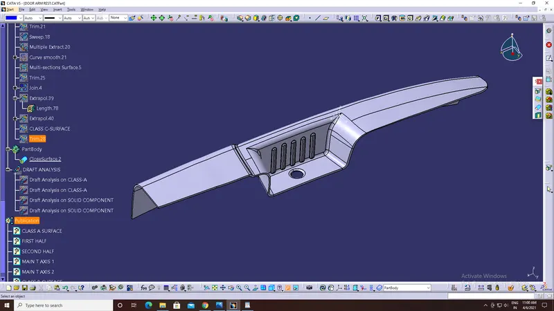
2. Using Fill option in part design window convert this surface to solid model.
G. Steps involved in DRAFT ANALYSIS ON Class A-Surface:
As mentioned above due to complexity of the component I have used two TOOLING AXES, so Draft analysis is done on both axes.
a. Along MAIN T AXIS 1:
1. Select 'Customize view parameters' from the 'View mode' and choose 'Materials'.
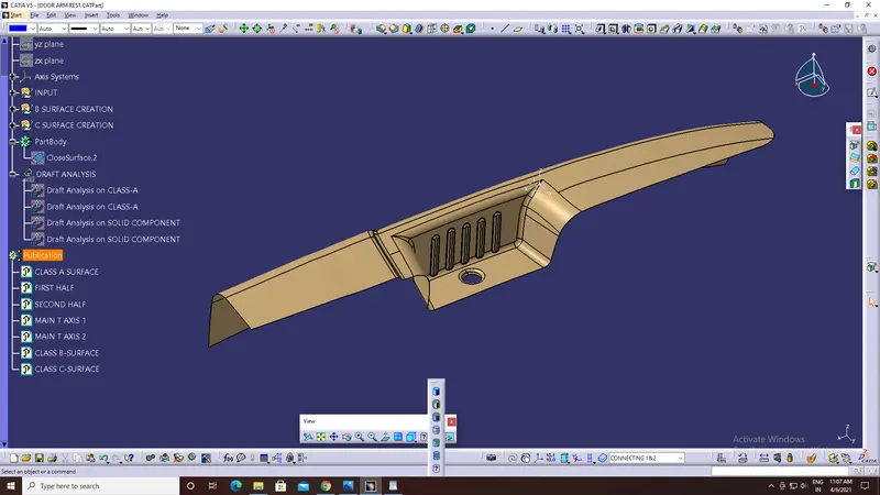
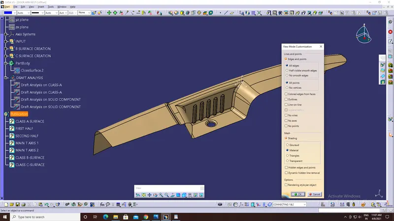
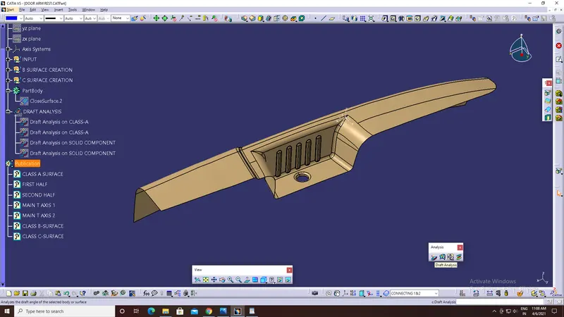
2. Select 'Feature Draft Analysis' from the 'Analysis toolbar'.
3. Now, holding the red-dot, which is on the compass (present on Top-right corner of the window) align with the Tooling axis and lock it.
Set the Minimum draft angle (3 degree for plastic components) in 'Draft Analysis..' dialog box.
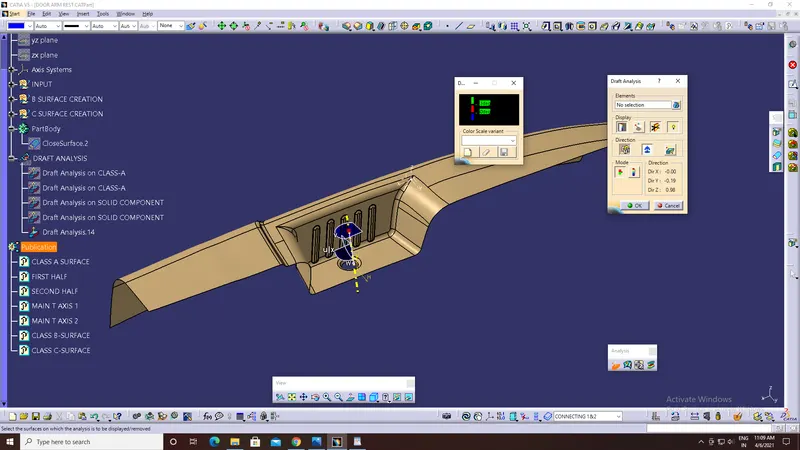
4. Choose 'Class A-Surface' as element in 'Draft Analysis' dialog box.
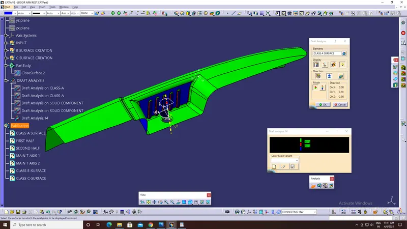
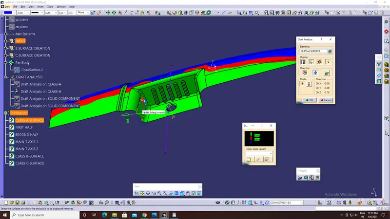
5. After selecting if the color changes to,
a. Green, then the draft of the Part has minimum draft angle of 3 degree.
b. Red, then the draft angle of the part lies between 0-3 degree.
c. Blue, then the draft angle of the part is less than 0 degree.
6. By choosing 'Analyse under running point' from 'Analysis toolbar' we can check the draft angle at any point on the surface just by moving the pin.
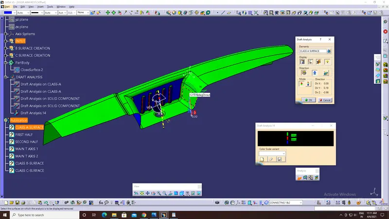
b. Along MAIN T AXIS 2:
Intial steps are same as done before only difference is we place the compass on other tooling axis.
1. Select 'Customize view parameters' from the 'View mode' and choose 'Materials'.
2. Select 'Feature Draft Analysis' from the 'Analysis toolbar'.
3. Now, holding the red-dot, which is on the compass (present on Top-right corner of the window) align with the Tooling axis and lock it.
Set the Minimum draft angle (3 degree for plastic components) in 'Draft Analysis..' dialog box.
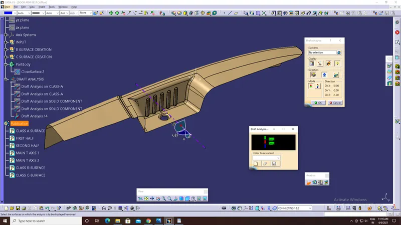
4. Choose 'Class A-Surface' as element in 'Draft Analysis' dialog box.
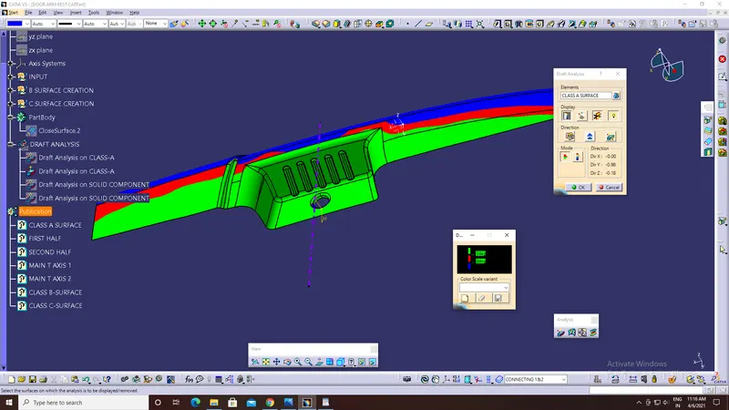
6. After selecting if the color changes to,
a. Green, then the draft of the Part has minimum draft angle of 3 degree.
b. Red, then the draft angle of the part lies between 0-3 degree.
c. Blue, then the draft angle of the part is less than 0 degree.
7. By choosing 'Analyse under running point' from 'Analysis toolbar' we can check the draft angle at any point on the surface just by moving the pin.
H. Steps involved in DRAFT ANALYSIS ON SOLID COMPONENT:
As mentioned above due to complexity of the component I have used two TOOLING AXES, so Draft analysis is done on both axes.
a. Along MAIN T AXIS 1:
Intial steps are same as done before only difference is we place the compass on other tooling axis.
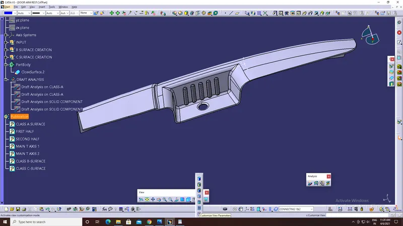
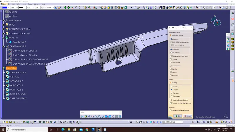
1. Select 'Customize view parameters' from the 'View mode' and choose 'Materials'.
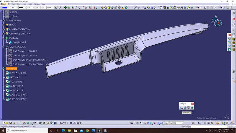
2. Select 'Feature Draft Analysis' from the 'Analysis toolbar'.
3. Now, holding the red-dot, which is on the compass (present on Top-right corner of the window) align with the Tooling axis and lock it.
Set the Minimum draft angle (3 degree for plastic components) in 'Draft Analysis..' dialog box.
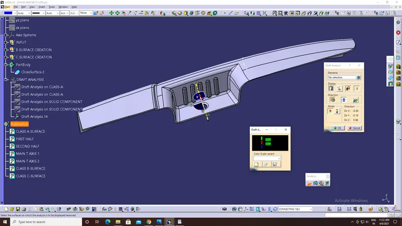
4. Choose 'Class A-Surface' as element in 'Draft Analysis' dialog box.
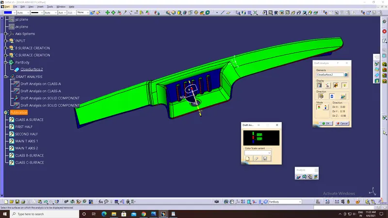
6. After selecting if the color changes to,
a. Green, then the draft of the Part has minimum draft angle of 3 degree.
b. Red, then the draft angle of the part lies between 0-3 degree.
c. Blue, then the draft angle of the part is less than 0 degree.
7. By choosing 'Analyse under running point' from 'Analysis toolbar' we can check the draft angle at any point on the surface just by moving the pin.
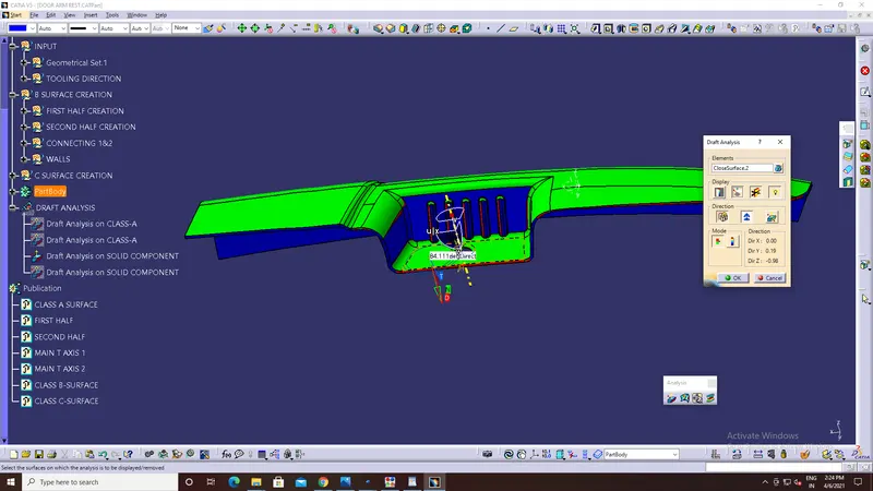
b. Along MAIN T AXIS 2:
1. Select 'Customize view parameters' from the 'View mode' and choose 'Materials'.
2. Select 'Feature Draft Analysis' from the 'Analysis toolbar'.
3. Now, holding the red-dot, which is on the compass (present on Top-right corner of the window) align with the Tooling axis and lock it.
Set the Minimum draft angle (3 degree for plastic components) in 'Draft Analysis..' dialog box.
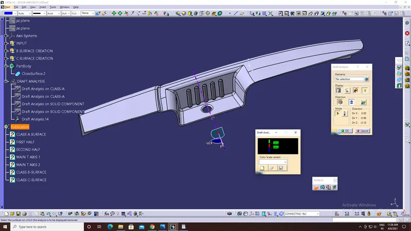
4. Choose 'Class A-Surface' as element in 'Draft Analysis' dialog box.
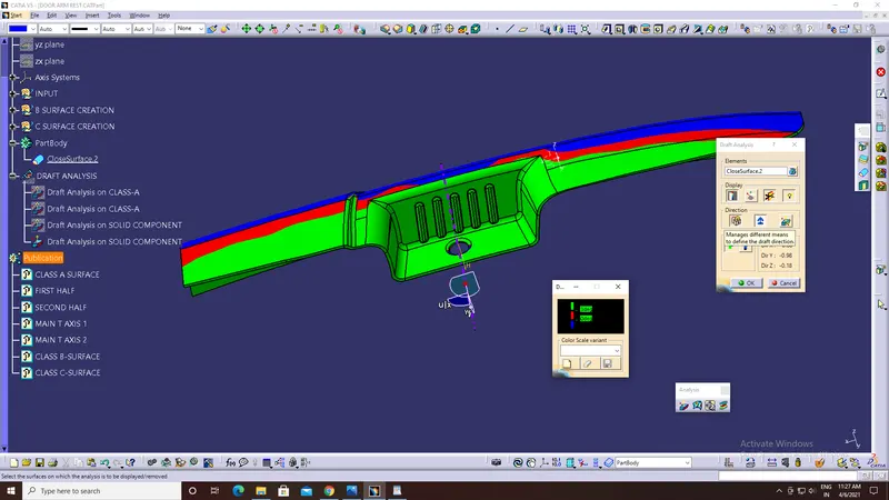
6. After selecting if the color changes to,
a. Green, then the draft of the Part has minimum draft angle of 3 degree.
b. Red, then the draft angle of the part lies between 0-3 degree.
c. Blue, then the draft angle of the part is less than 0 degree.
7. By choosing 'Analyse under running point' from 'Analysis toolbar' we can check the draft angle at any point on the surface just by moving the pin.
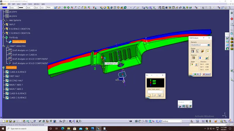
I. Screenshot of publication CLASS A, B, C-SURFACES and Tooling axes of Door arm rest.
Conclusion: Door arm rest component is created using the Class A-surface and draft analysis is also performed on both. The draft conditions for both Class A-surface and solid component is satisfied.