Week 8 - Challenge 1 - Draft Analysis on a Fan Cover
Aim: Draft Analysis on Fan Cover.
Description:
Draft Analysis:
Draft is the angle in which the part is tapered for easy ejection from core and cavity block.
Draft analysis is a technique used to analyze whether the drafted CAD model is manufacturable with the given draft conditions. Tooling axis (the direction in which the mold is ejected) is provided, so that there should be a smooth ejection of the surface/part from Core-Cavity block.
Draft angle 3 degree (Min for plastic components), 0.5 degree (Min for Engineering features), 7 degree (Min for sheet metal).
Steps involved in creating TOOLING AXIS:
1. Create an Axis system at the center of the hole as shown in figure.
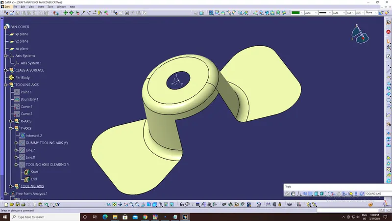
2. Create an intersecting curve (using XZ-plane and the Class-A surface of fan cover).
(Note: Part is colored for highlighting the 'INTERSECTION LINE'.)
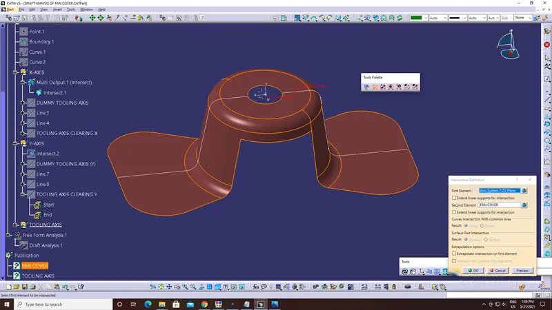
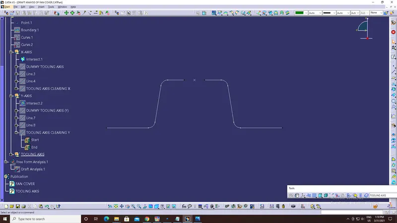
3. Add a dummy tooling axis.
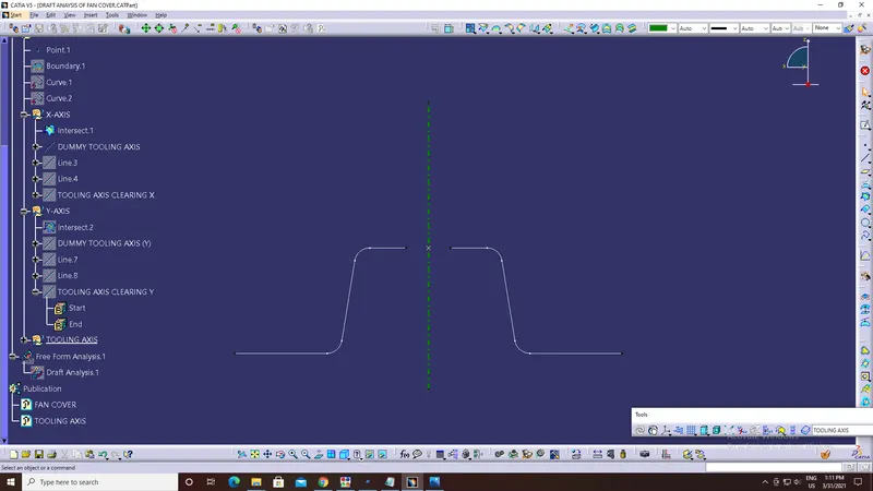
4. Create lines on the intersecting curve (which are parallel to the dummy tooling axis).
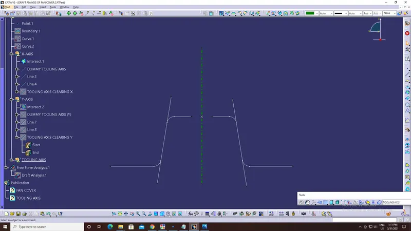
5. Now, create a bisecting line using the lines (parallel to dummy tooling axis) and a point.
This bisecting line will be our Tooling axis clearing in X-direction.
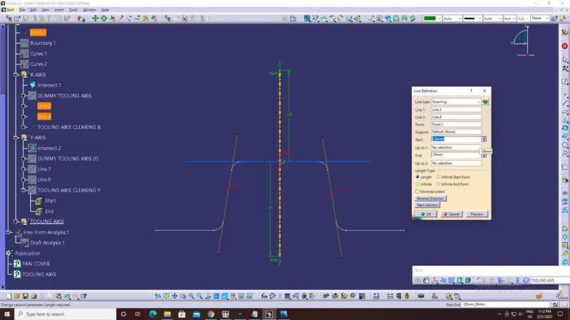
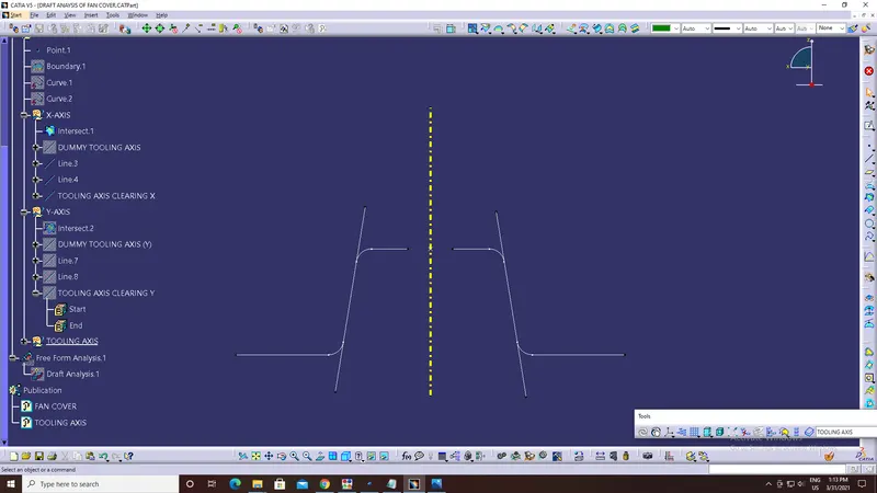
6. By selecting the appropriate axis, plane and following the above steps we can create a Tooling axis in Y-direction.
(Note: Part is colored for highlighting the 'INTERSECTION LINE'.)
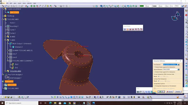
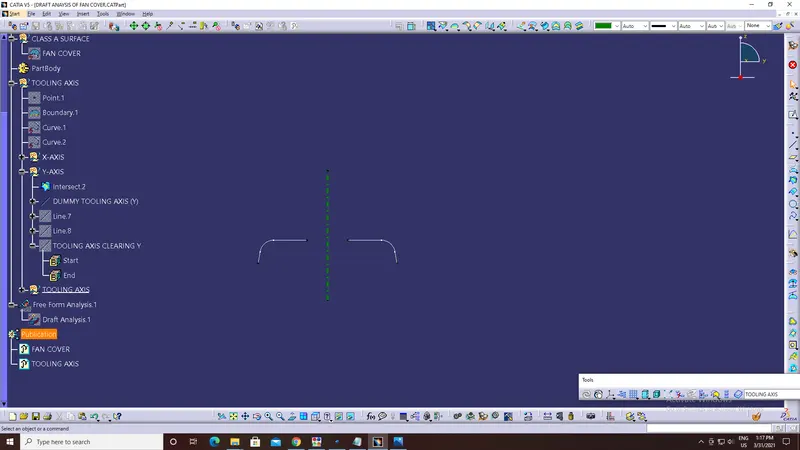
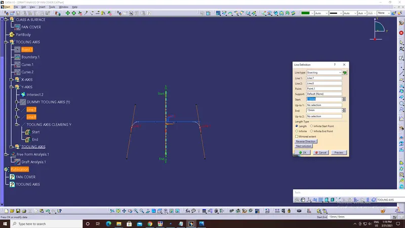
7. Publish Tooling axis and Fan cover for easy selection.
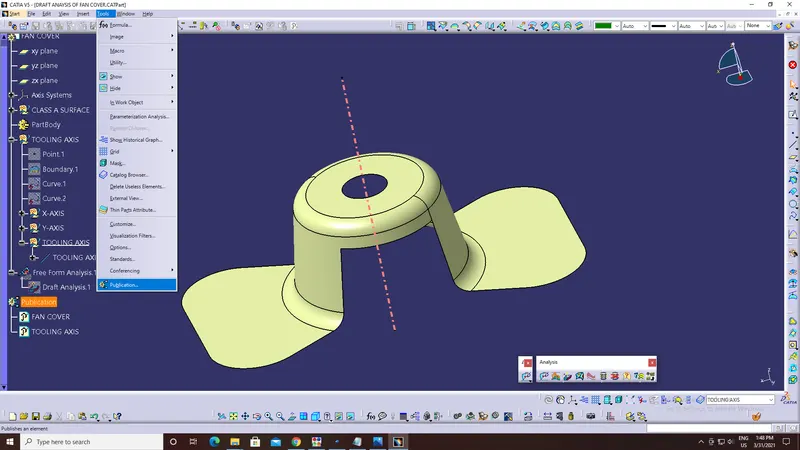
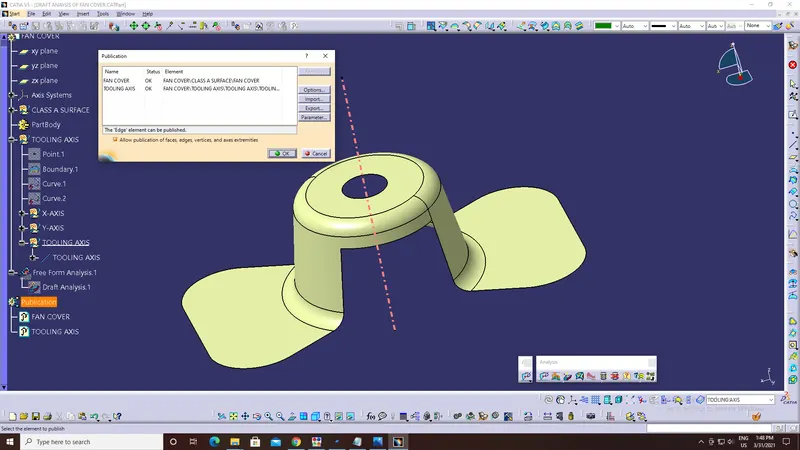
8. Finally, using the Tooling axis of X and Y direction create a bisecting line, which will be the Tooling axis for whole CAD part.
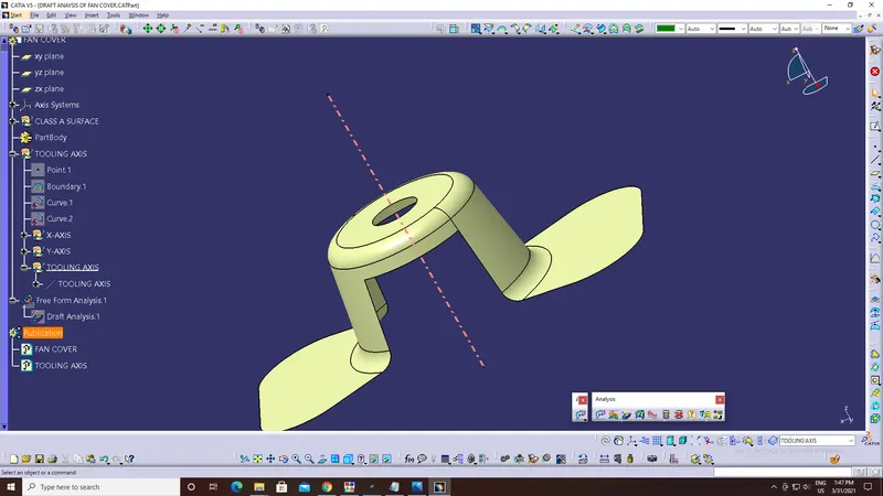
Steps involved in DRAFT ANALYSIS OF FAN COVER:
1. Select 'Customize view parameters' from the 'View mode' and choose 'Materials'.
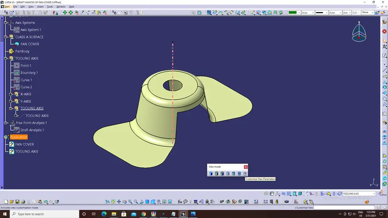
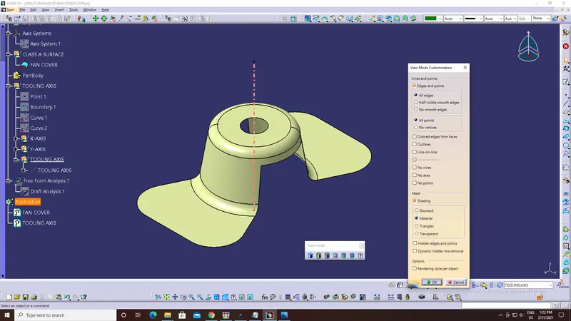
2. Select 'Feature Draft Analysis' from the 'Analysis toolbar'.
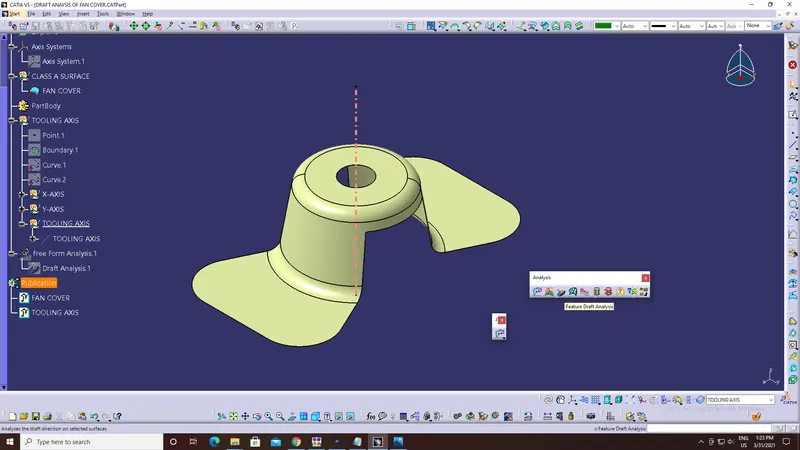
3. Now, holding the red-dot, which is on the compass (present on Top-right corner of the window) align with the Tooling axis and lock it.
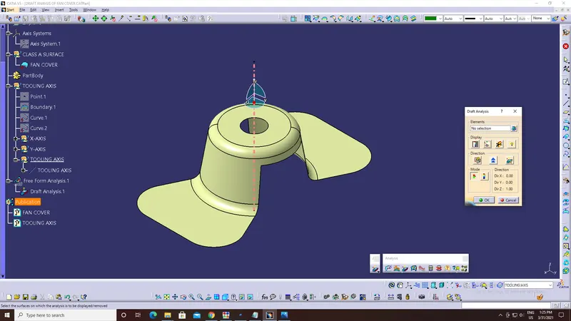
4. Set the Minimum draft angle (3 degree for plastic components) in 'Draft Analysis.1' dialog box.
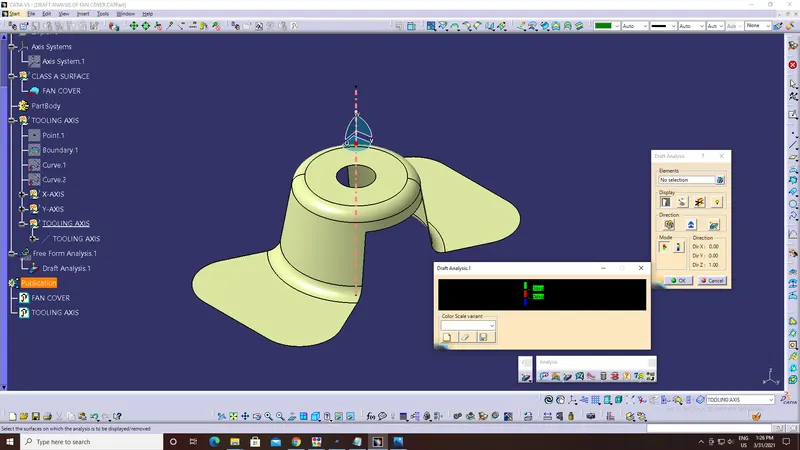
5. Choose 'Fan Cover' as element in 'Draft Analysis' dialog box.
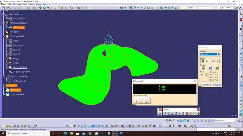
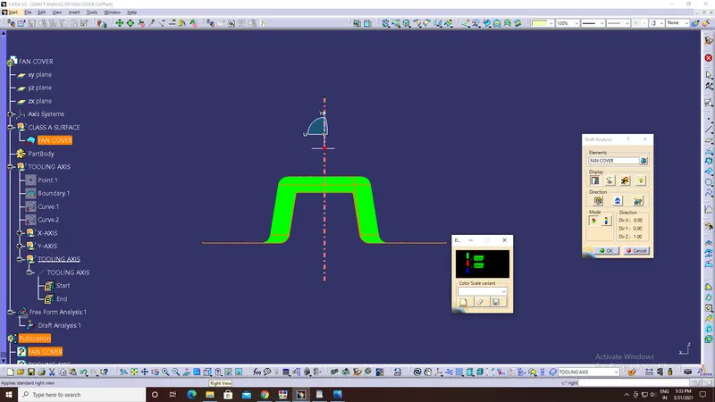
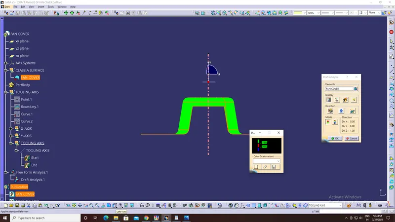
6. After selecting if the color changes to,
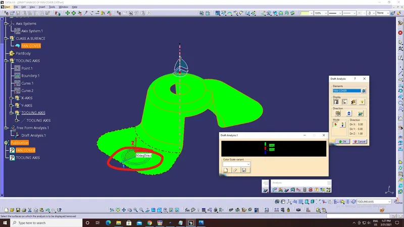
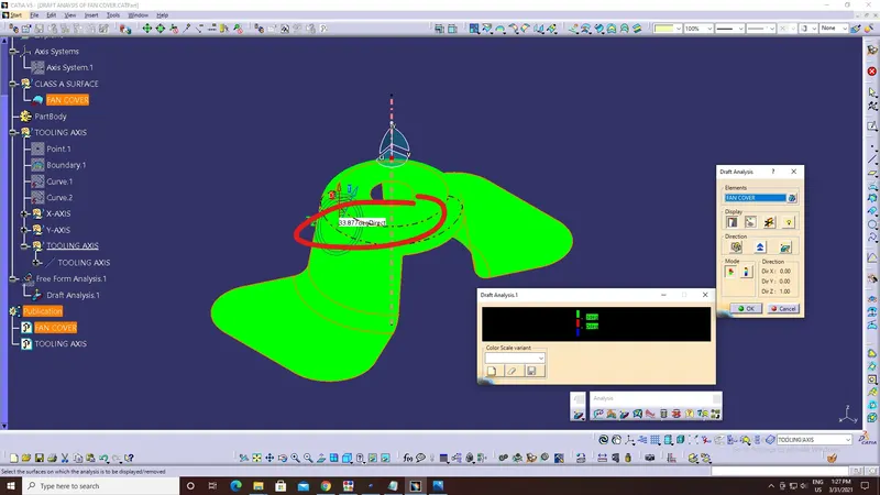
a. Green, then the draft of the Part has minimum draft angle of 3 degree.
b. Red, then the draft angle of the part lies between 0-3 degree.
c. Blue, then the draft angle of the part is less than 0 degree.
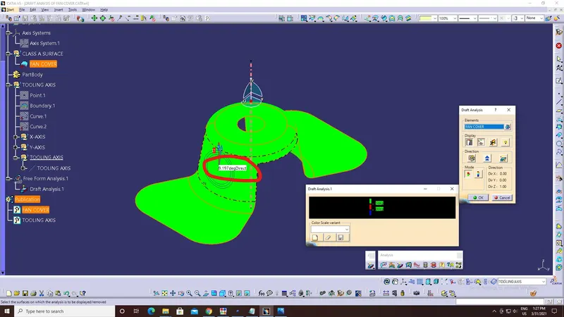
7. By choosing 'Analyse under running point' from 'Analysis toolbar' we can check the draft angle at any point on the surface just by moving the pin.
Screenshots of the model in different view:
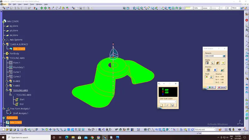
a. Isometric View:
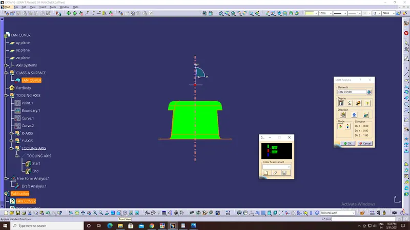
b. Front View:
c. Right-side View:
d. Left-side View:
e. Top View:
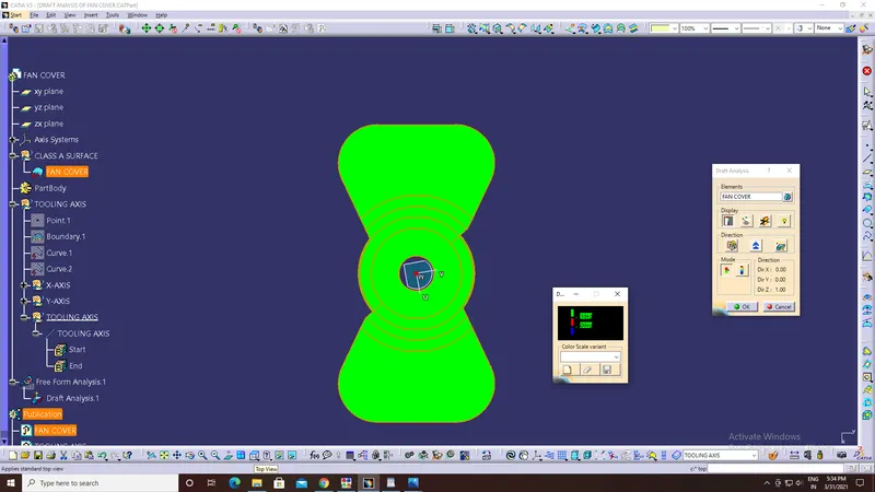
Conclusion: Draft analysis was conducted on the fan cover and it meets all the draft conditions.