Week 11 - Final project
REPORT :
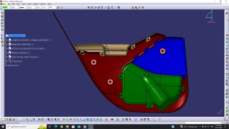
CLASS A SURFACE: Taken from the given Class A inputs. Surfaces with errors are corrected wherever required.
CLASS B SURFACE: Offset for 2.5mm from Class A surface. Holes, empty patches, and defects are fixed.
CLASS C SURFACE: Created by using the Sweep and multisection commands with a draft angle of 3 degrees.
HEAT STAKES and FLANGES: 12 heat stakes are created with a minimum draft angle of 0.5 deg and the respective flanges are also created with 2.5mm thickness.
DOGHOUSE: 3 dog houses are in total, 2 on the lower substrate and 1 on the middle part. 3 push pins are also attached on top of each dog house.
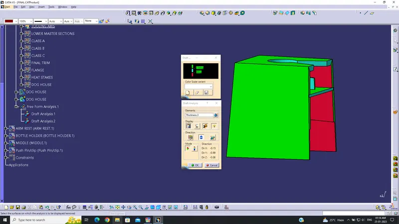
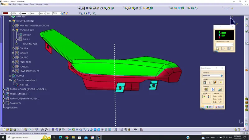
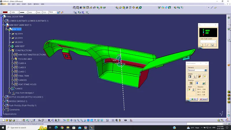
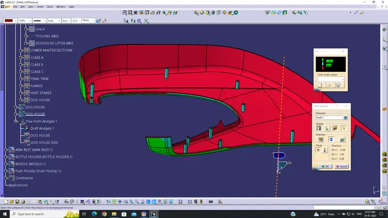
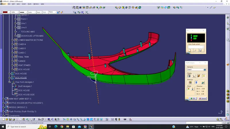
DRAFT ANALYSIS: Analysis shows no defects on the bottle holder and middle parts. However, there is a major defect on the armrest and minimal defects on the lower substrate which needs to be rectified.
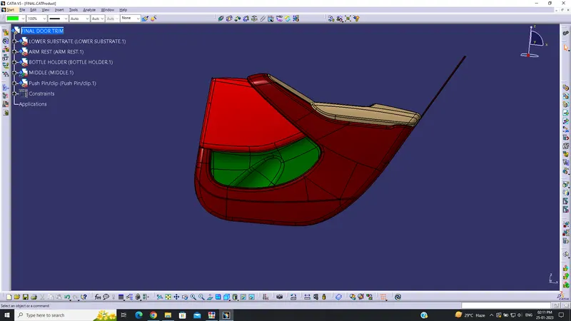
DETAILED REPORT :
BOTTLE HOLDER :
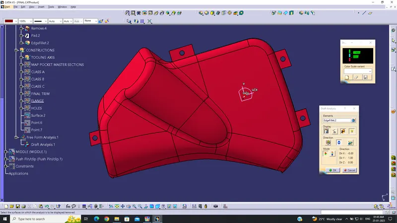
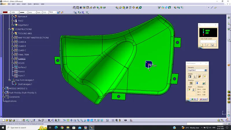
The tooling axis is created first by taking a point from an extract of the class a surface and then creating a normal line from the line tool, this line is the tooling axis.The A-surface is offset to distance of 2.5 mm. Then it is extrapolated along the edges to create the B-surface. Then the C-surface is done by creating sweep from the A-surface at a draft angle of 3 degree. The corner surfaces are created using multi section surface and trimmed together to form the C-surface. The A-surface and C-surface are joined then trimmed with the B-surface to form a closed surface which is then turned into a solid in the part design using the close surface command.Flanges are also attached at desired positions with holes for the heat stakes to fit.
The draft analysis is done and the results are satisfactory. The C-surface clears the draft angle of 3 degrees. The visual check shows that there are no issues with the draft analysis.
ARM REST :
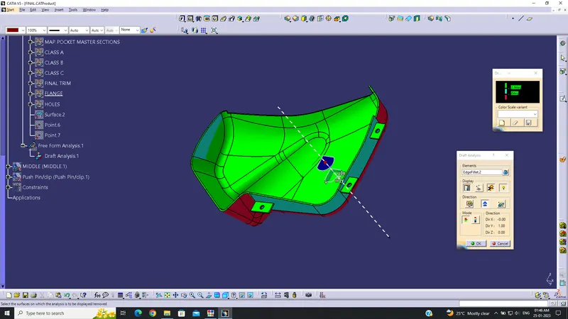
The top part of the lower doortrim is the armrest which sits above the lower substrate. The given A-surface had some issues which are rectified by removing the surfaces with error and later joined using multisection command. The tooling axis is created by taking a normal line command from the flat base surface which is extracted. Then the surface is offsetted for 2.5mm as the B-surface, this surface had some errors which were corrected. Then the C-surface is done by using sweep from the A-surface at a draft angle of 3 degree. The corner surfaces are created using multi section surface and trimmed together to form the C-surface. The A-surface and C-surface are joined then trimmed with the B-surface to form a closed surface which is then turned into a solid in the part design using the close surface command. Flanges are also attached at desired positions with holes for the heat stakes to fit.
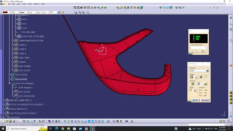
The draft analysis was done for the arm rest and the results were are not perfect. There are a few surfaces where the draft analysis is not clearing. These surfaces are seen in red colour at the sides from the draft analysis. These surfaces should be rectified in order to clear the draft analysis.
LOWER SUBSTRATE :
This is the part which holds the lower door trim components. The tooling axis is created by taking a normal line command from the flat base surface which is extracted. Then the surface is offset for 2.5mm as the B-surface, this surface had some errors which were corrected. Then the C-surface is done by using a sweep from the A-surface at a draft angle of 3 degrees. The corner surfaces are created using multi-section surface and trimmed together to form the C-surface. The A-surface and C-surface are joined and then trimmed with the B-surface to form a closed surface which is then turned into a solid in the part design using the close surface command. Heat stakes are created and attached to the lower substrate using Boolean operation. They are used for part to part attachment.
The draft analysis was done for the lower substrate and the results are satisfactory . There a few edges on the C-surface where the draft analysis are not clearing. These surfaces are seen in red colour from the draft analysis. But these surfaces are only at 0.1 - 0.3 degrees off. Hence they should not cause any issues but should still be rectified.
MIDDLE:
The part which is in between the lower substrate and above the bottle holder is named as middle part. The tooling axis is created first by taking a point at the centre of the class a surface and then creating a normal line, is the tooling axis.The A-surface is offset to distance of 2.5 mm which is then extrapolated along the edges to create the B-surface. Then the C-surface is done by creating sweep along the edges at a draft angle of 3 degree. The corner parts are created using multi section surface and trimmed together to form the C-surface. The A-surface and C-surface are joined then trimmed with the B-surface to form a closed surface which is then turned into a solid in the part design using the close surface command. A dog house is attached as B-surface features.Flanges are also attached at desired positions with holes for the heat stakes to fit.
The draft analysis of the middle part is satisfactory and the C-surface clears the draft angle of 3 degrees. The visual check shows that there are no issues with the draft analysis.
DOG HOUSE:
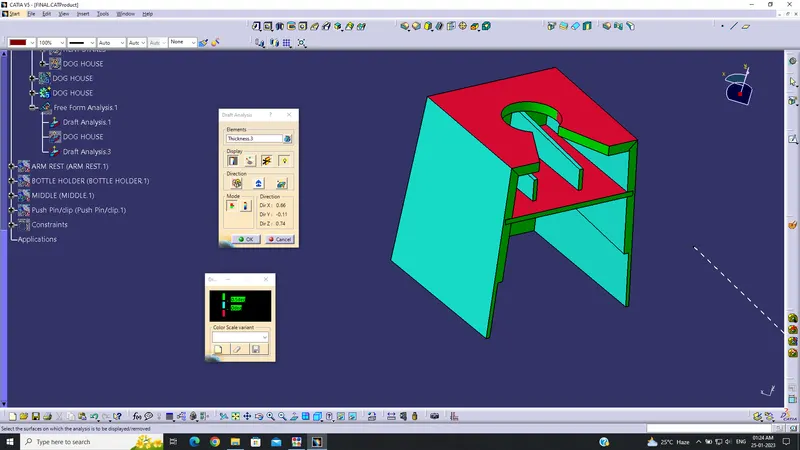
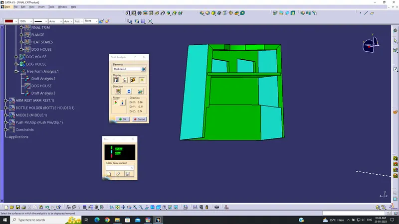
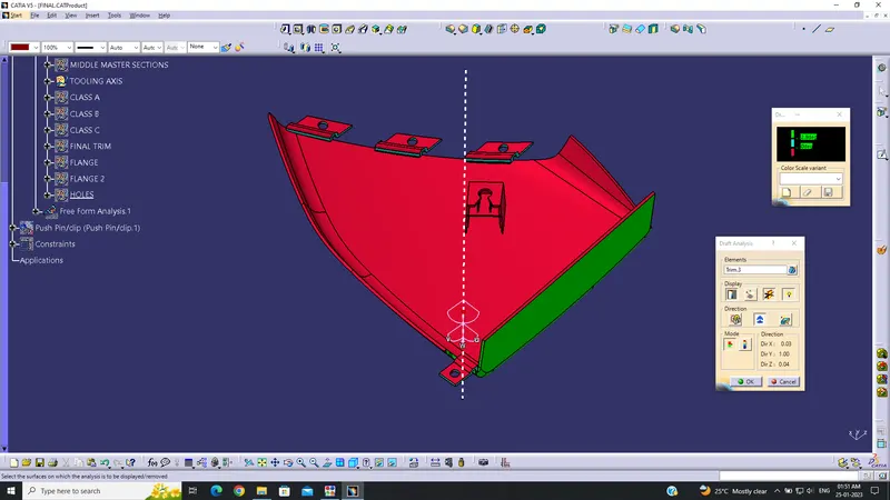
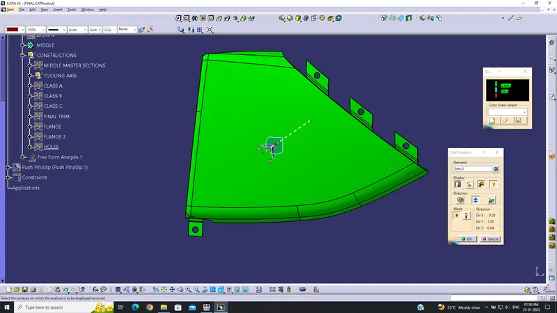
The dog houses are created and a total of three dog houses are attached in the lower door trim. Two dog houses are attached on the lower substrate and one dog House attached on the middle part B-surfaces. Three push pins are also attached on top of each dog house. The dog house clear the draft analysis. But the top surface shows error. The draft is done by creating a Dog house lifter axis
.