Week 11 - Final project
Final project
Door panel attachment
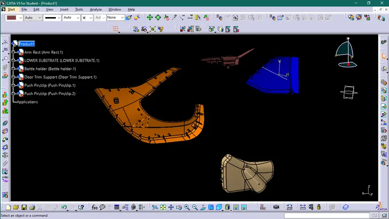
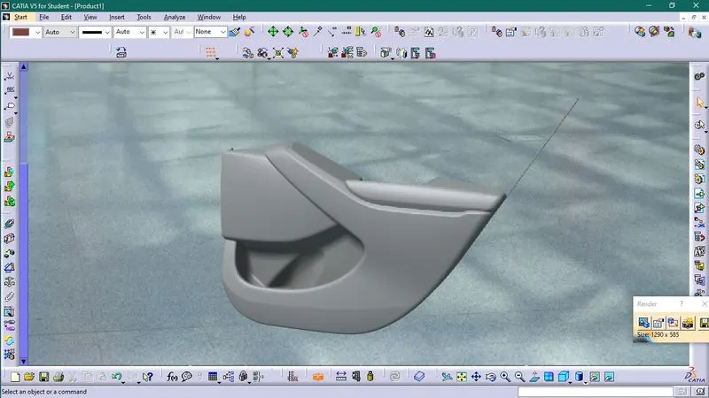
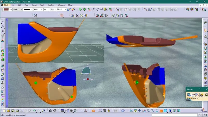
The given Master section surfaces contain four different parts which are Lower Substrate, Upper Substrate, Bottle holder, and Armrest. Our task is to create thickened master section with attachment features. Also, we have done a draft analysis on each part to check molding feasibility.
Master section
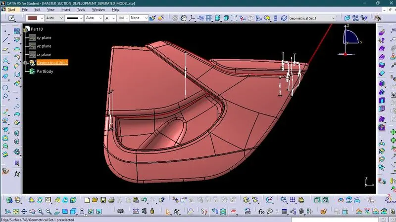
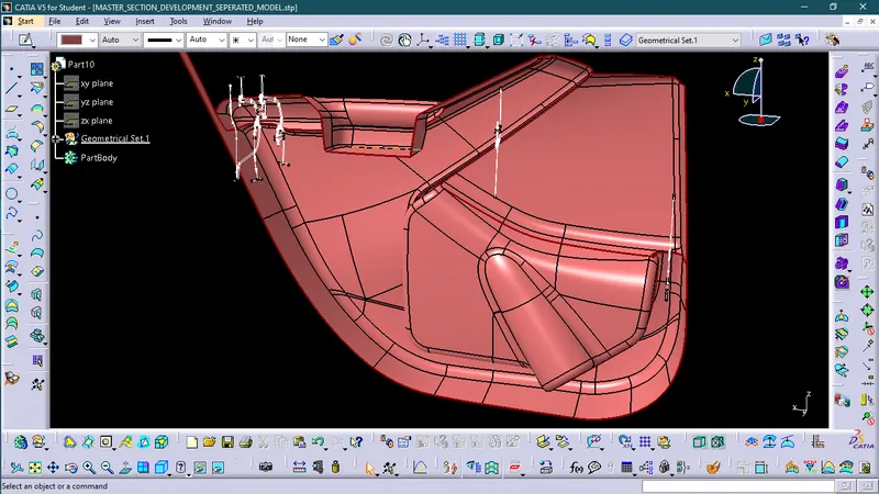
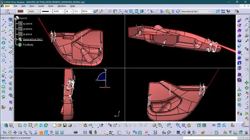
Arm Rest
Class A surface
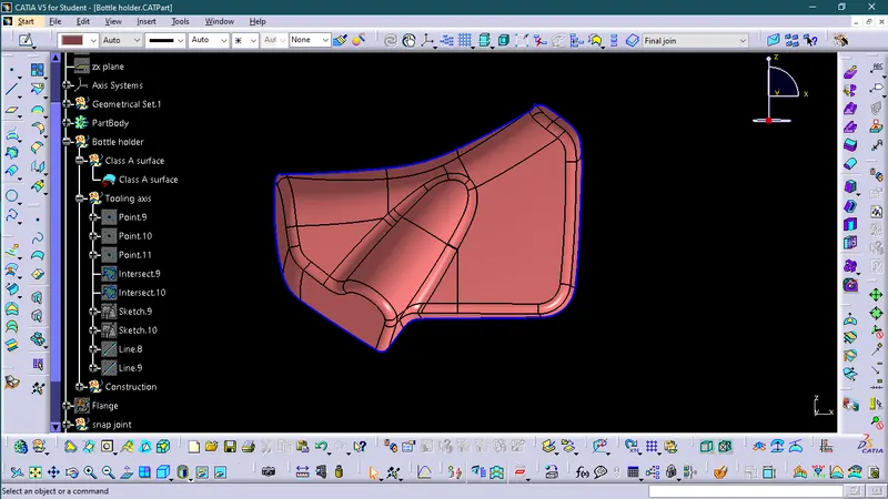
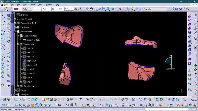
As the part file is a class A surface, therefore, we first have to create a solid part with the help of Class A. Assuming thickness for the part as 2.5 mm.
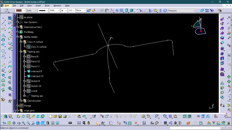
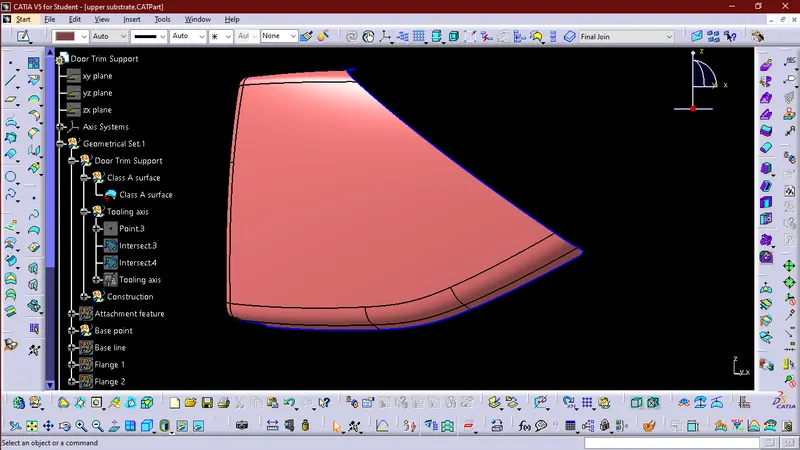
First, we create a tooling axis for it by using the intersection method.
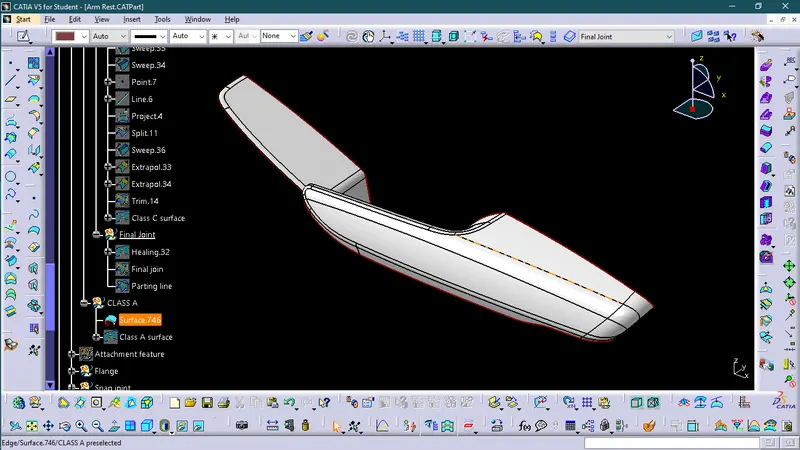
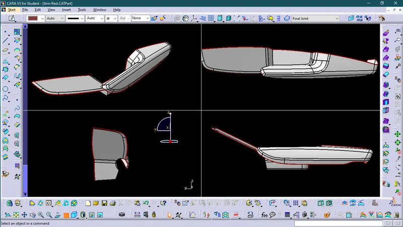
Boundary in Class A surface
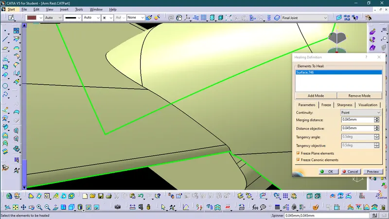
As we can see there is the presence of an open boundary issue in the given Class A surface. However, modification is not allowed in class A but to create a closed surface we have to improve it by using the healing command.
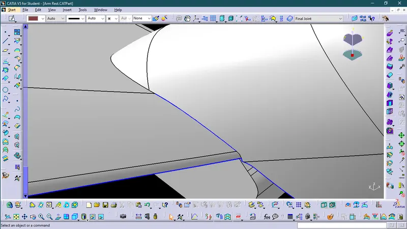
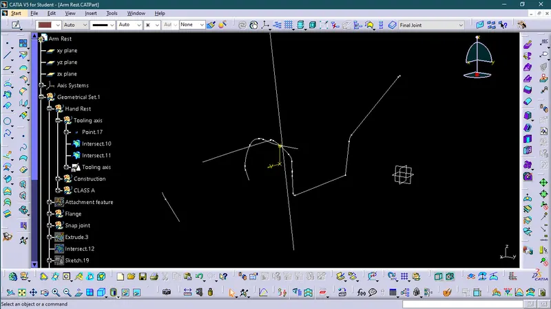
Tooling Axis
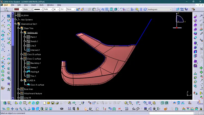
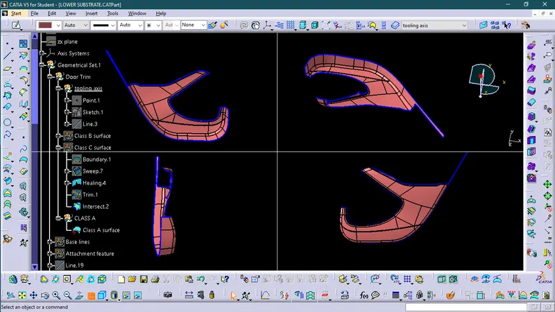
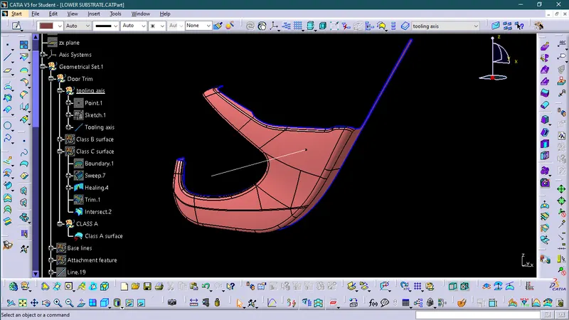
The ejection from the mold after manufacturing the interior trim must have the nominal 3-degree draft angle. Hence, the tooling directions created by considering the above factor and bisecting method is used. The base surface of the class-A was extracted to create a reference point on the surface using the point, create a line in the z-direction and an axis system was inserted to the point then using projection intersection along the yz plane is made and the two inclined lines were drawn inside the positioned sketch. then bisecting lines with the two inclined lines were created. Bisecting these two lines sketch1 and sketch2 the bisecting line is created and published as a tooling axis.
Draft Analysis
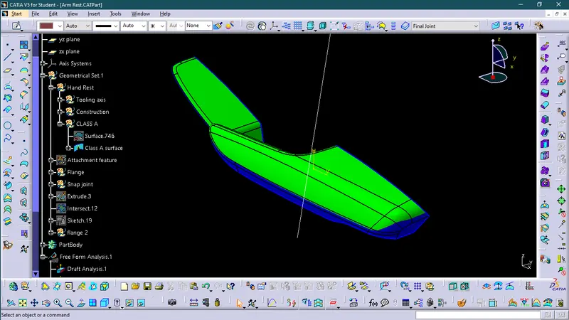
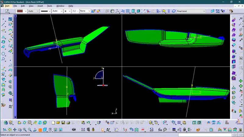
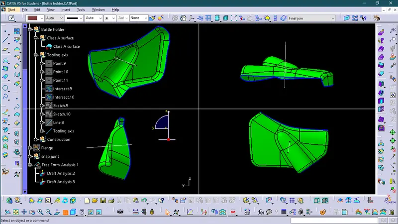
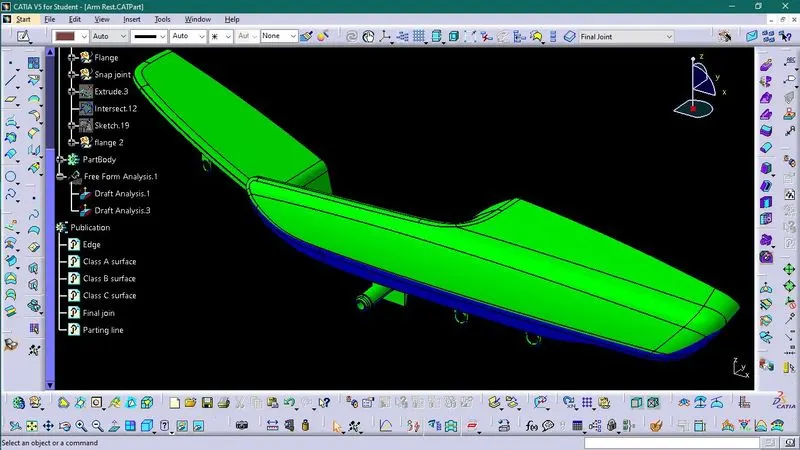
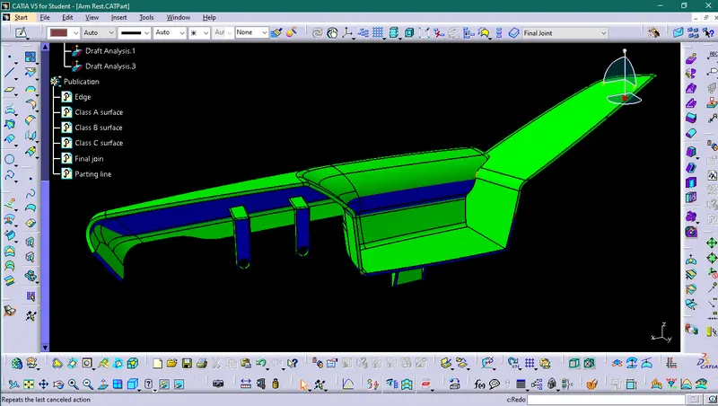
- First the class – A surface is checked before creating the Class –B&C surface and finally the solid body must be analyzed. Both can be done by following the below procedures.
- By changing the view mode to custom view parameters – Material mode then the feature draft analysis is enabled.
- Then the compass was activated and placed with the tooling axis by dragging the red pointer and then locking it.
- Then, by selecting the quick analysis mode, the nominal value will be 3 degrees and checked for the component's draft angle.
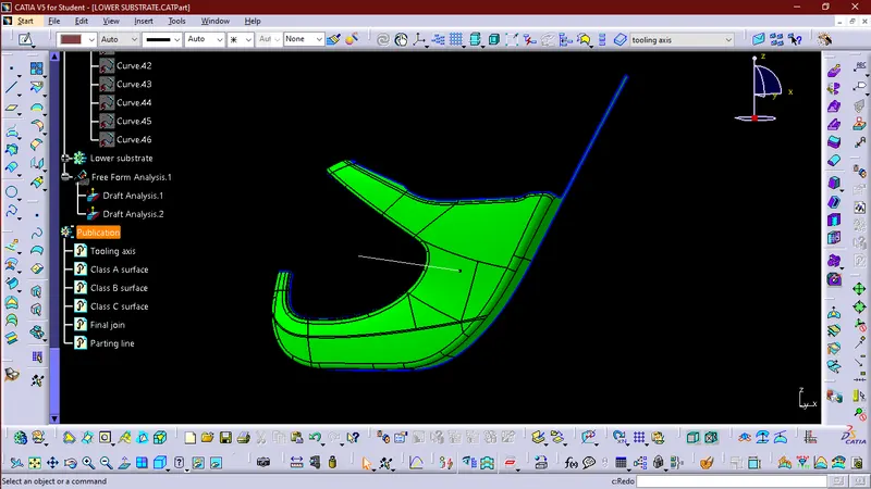
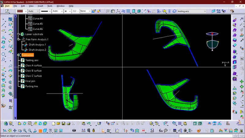
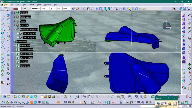
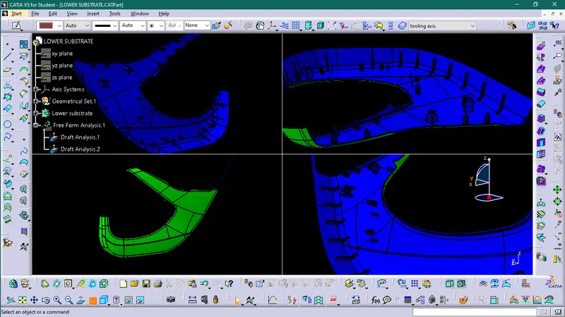
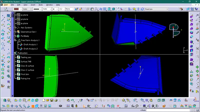
- The green color area shows that it satisfies the 3-degree draft angle. If not satisfied then by using the Running point tool the area is measured and then altered to get a successful draft for the created tooling direction.
Class B surface
Procedure to create Class B surface
- First, we will offset the Class A surface in the reverse direction to 2.5 mm.
- However, surface A can not be fully offset and create some missing parts.
- Now we will repair our Class B surface and fill up those missing parts by using the following commands:-
- Extract
- Offset
- Extrapolate
- Blend
- Split
- Trim
- Isoparametric curve
- Heal
- Surface simplification
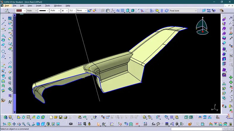
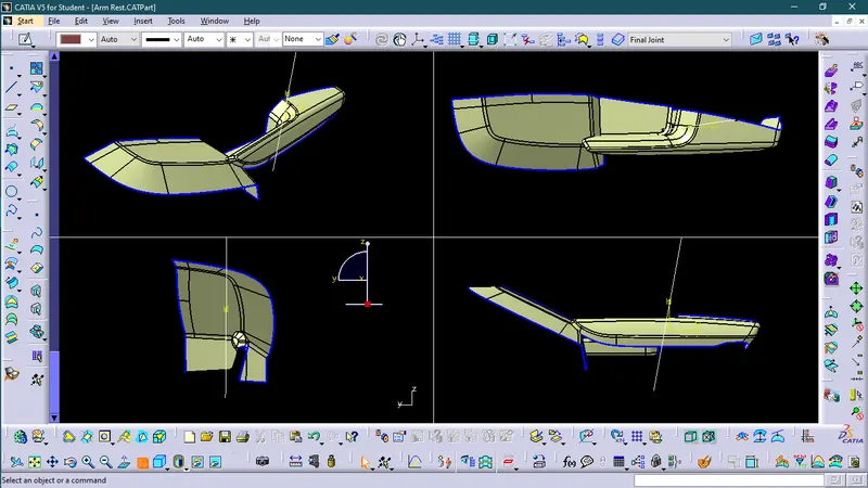
Class C surface
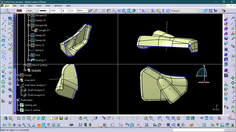
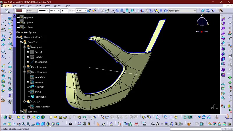
Then we created a Class C surface by using the sweep tool
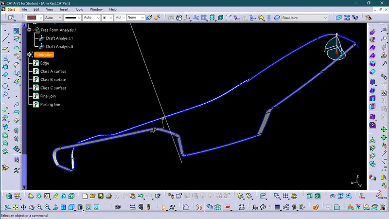
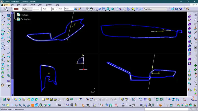
Final Join
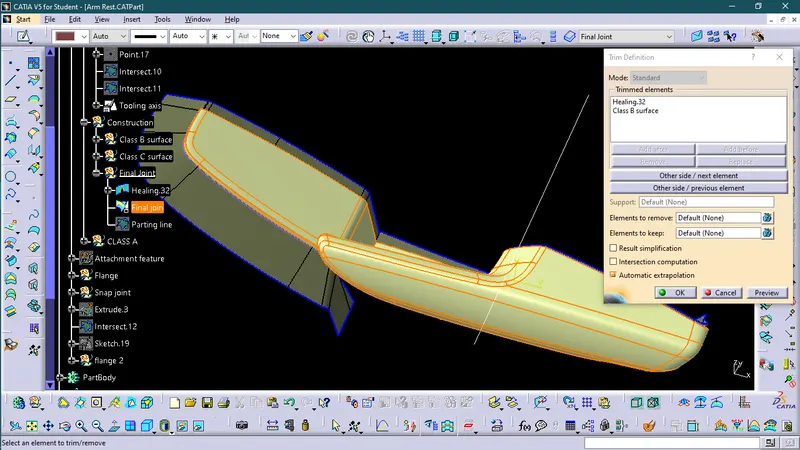
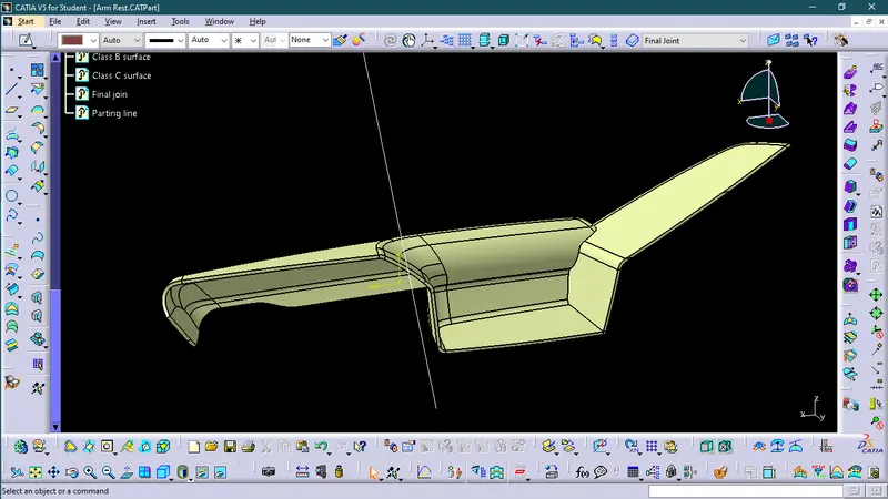
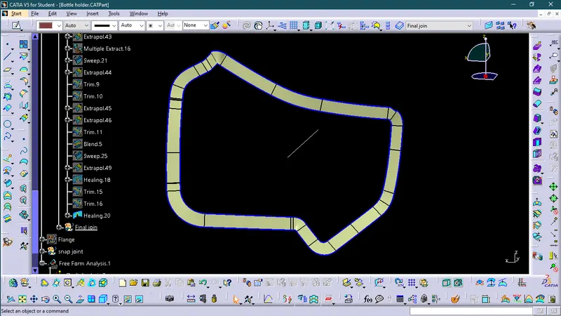
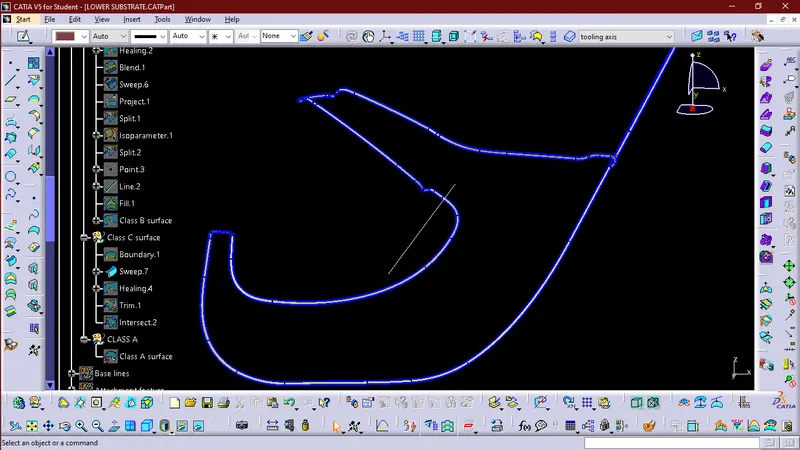
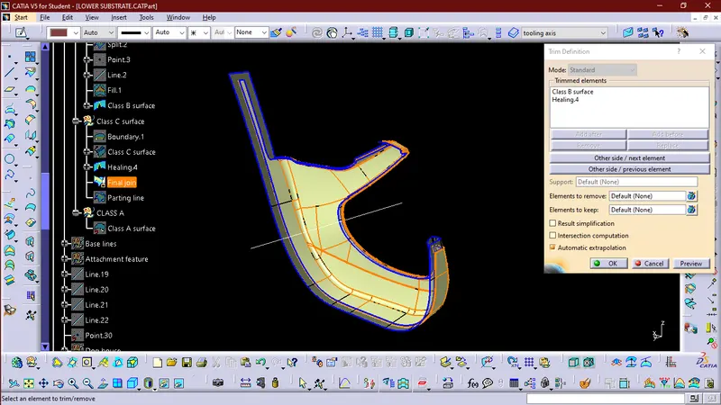
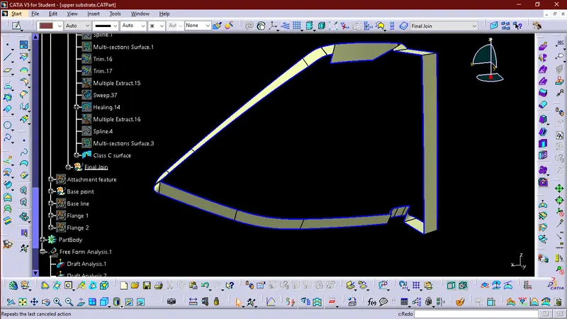
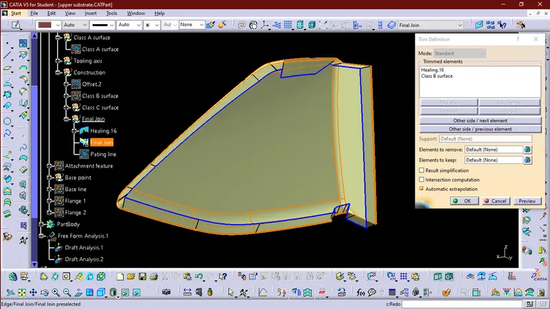
To make sure that there is not any open boundary between class A and class C, we have used the join option to create the single body. This is done to make sure that the parting line doesn't lie between these two surfaces.
Parting Line
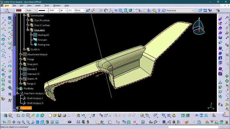
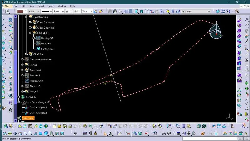
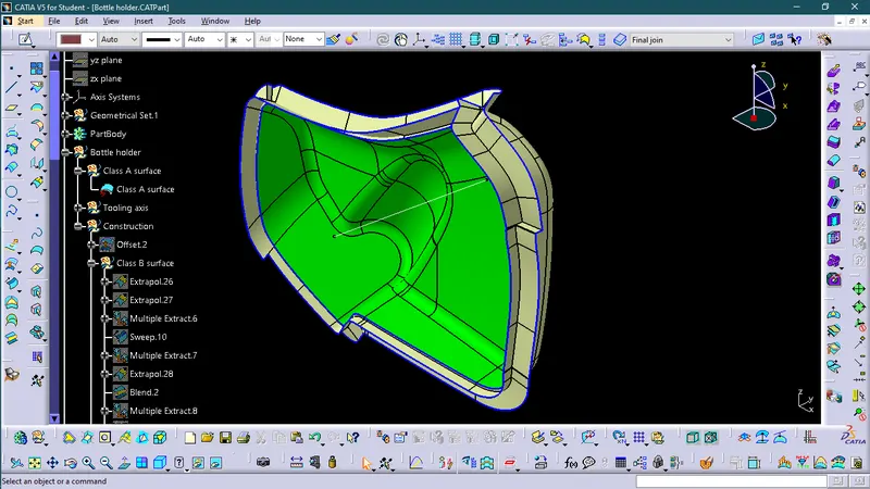
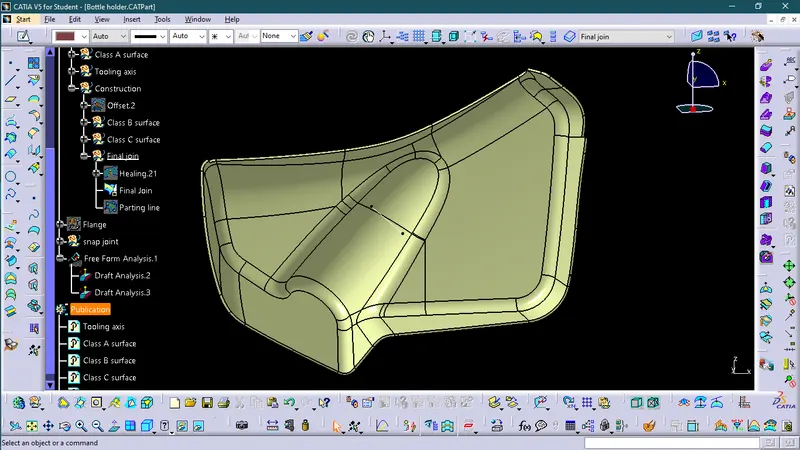
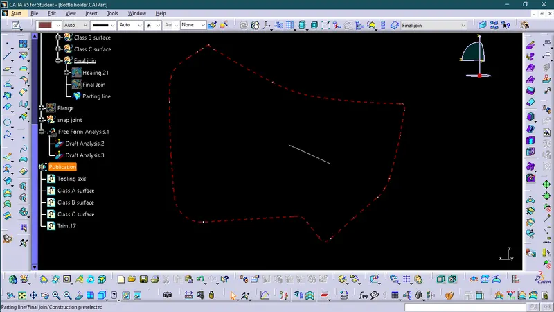
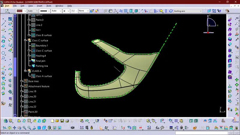
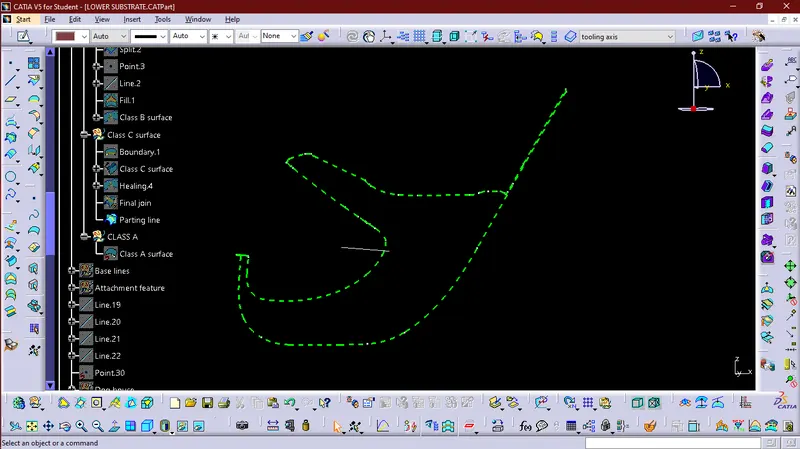
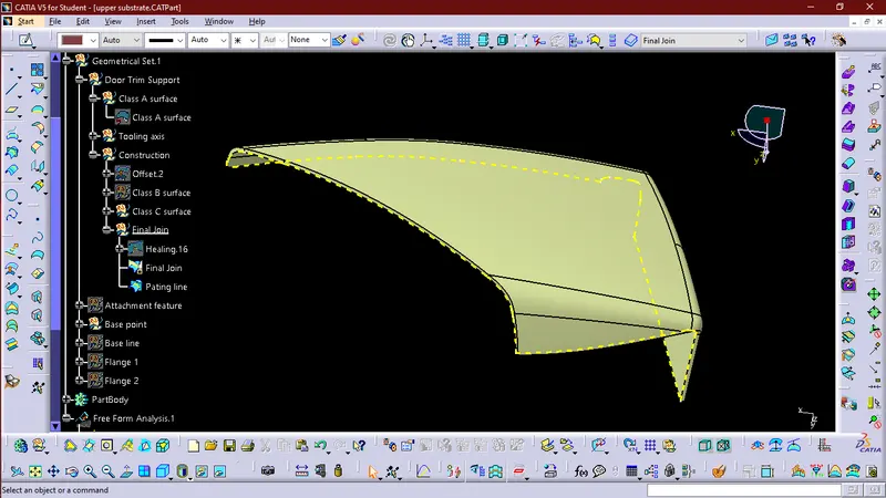
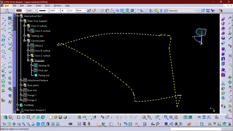
Generally, injection mold has two major components: the movable half and the fixed half, during the injection molding process, these two halves are pressed tightly from a sealed hollow to avoid melt flow leakage and maintain certain holding pressure, the pressed surface is called parting surface, usually, parting surface are the biggest projection outline of the part.
- A parting line is an inevitable part of injection-molded products.
- It is the line of separation between where two halves of a mold meet.
- It manifests itself on injection molded parts as a line that runs the entire perimeter of the part.
- In most parts, it is just a line that runs straight down the middle.
Bottle Holder
Class A Surface
Tooling Axis
Draft Analysis
Class B Surface
Class C Surface
Final Join
Parting Line
Lower Substrate
Class A Surface
Tooling Axis
Draft Analysis
Class B surface
Class C Surface
Final Join
Parting Line
Upper Substrate
Class A surface
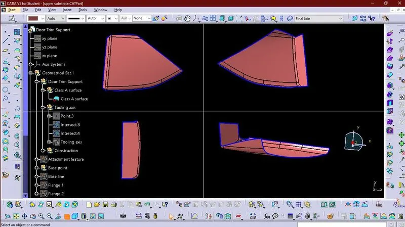
Tooling Axis
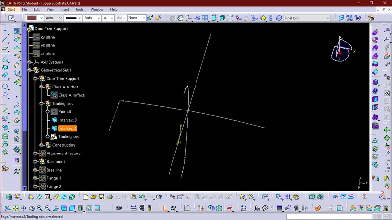
Draft Analysis
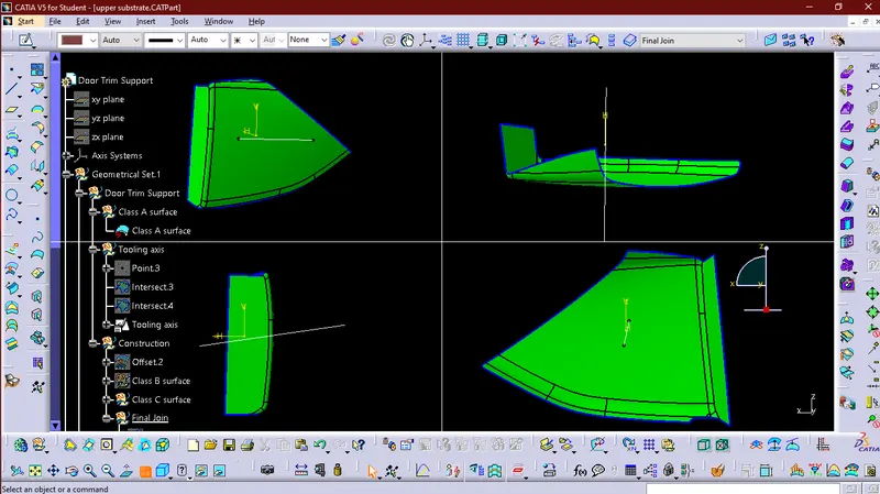
Class B Surface
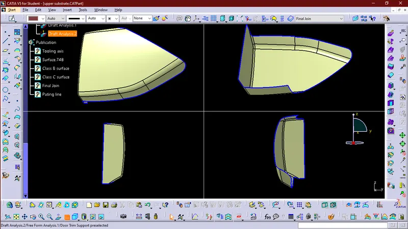
Class C Surface
Final Join

Parting Line
Attachment Features
Heat Stack
Heat staking also known as thermoplastic staking is the process of joining two dissimilar materials together. In heat staking, we use local heating and cooling to raise the temperature of plastic components and allow plastic reforming to be carried out.
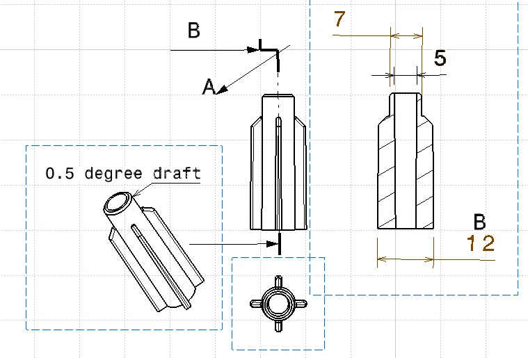
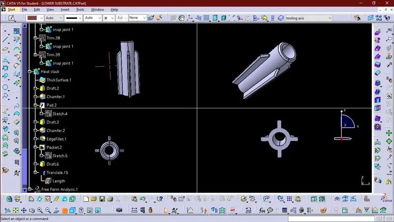
Flange
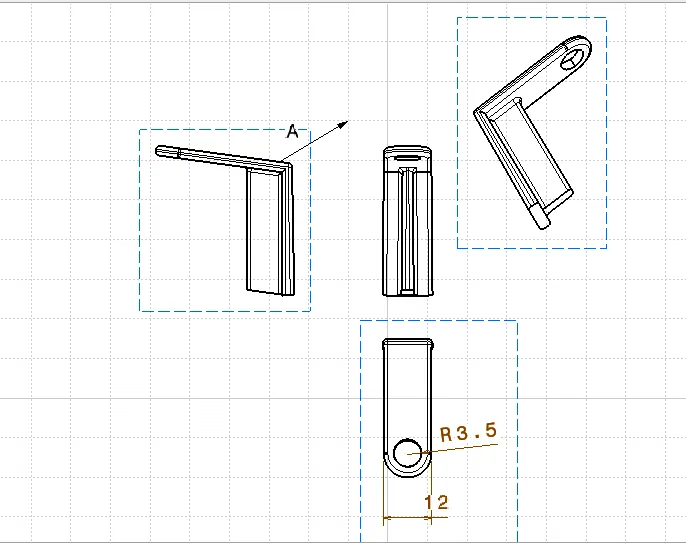
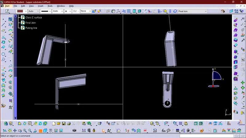
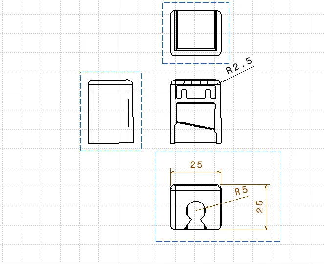
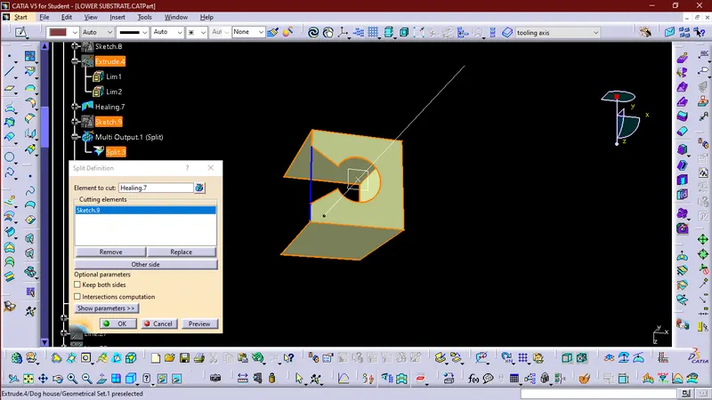
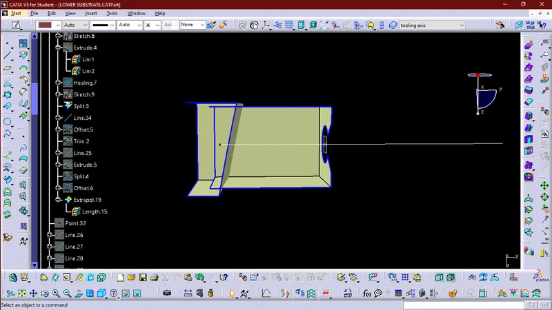
Dog House with keyhole
The dog house is an engineering feature used in the plastic trim design. Dog houses are used as supporting features. Sometimes other engineering features like snaps; locators, etc. are mounded on them to increase their strength. Dog houses are subjected to draft analysis to prevent breakage of the component during ejection from the mold cavity. Dog house and other engineering components are built on B-surface.
DESIGN CONSIDERATION FOR PLASTICS:
1. WALL THICKNESS:
Thick sections waste material and are simply uneconomic. So solid shapes that would do the job well in wood or metal must be transformed to a 'shell' form in plastics. This is done by hollowing out or 'coring' thick parts so you are left with a component that regardless of complexity is composed essentially of relatively thin walls joined by curves, angles, corners, ribs, steps, and offsets. As far as possible, all these walls should be the same thickness. The Wall thickness guide range is 0.75 mm to 3 mm for reinforced materials and 0.5 mm to 5 mm for unreinforced materials.
|
WALL THICKNESS(W) =0.70*(NOMINAL THICKNESS OF PLASTIC MATERIAL) |
2. CORNER RADII
Properly designed corners will make a big difference to the quality, strength, and dimensional accuracy of molding. But there is another benefit too. Smooth curved corners help plastic flow in the mold by reducing pressure drops in the cavity and minimizing flow-front break-up. Internal radii should be at least 0.5 and preferably 0.6 to 0.75 times the wall thickness.
|
CORNER RADII= (0.6-0.75) * (NOMINAL THICKNESS OF PLASTIC MATERIAL) |
3. DRAFT ANGLE:
Tooling must be cleared for easy ejection of the component, from the core cavity. In order to clear tooling certain value of draft is given to the component. Minimum of 2-3deg is provided on all plastic components.
|
DRAFT ANGLE=2-3 DEGREE |
4. FILLETS:
|
Fillet on the inner side = 0.25 * Thickness of the plastic material Fillet on the outer side = 1.25 * Thickness of the plastic material Fillet on the coring edges = 0.25 * Thickness of the plastic material Coring thickness = 0.40 * Thickness of the plastic material |
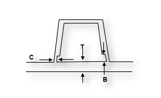
Design Rule of Dog House
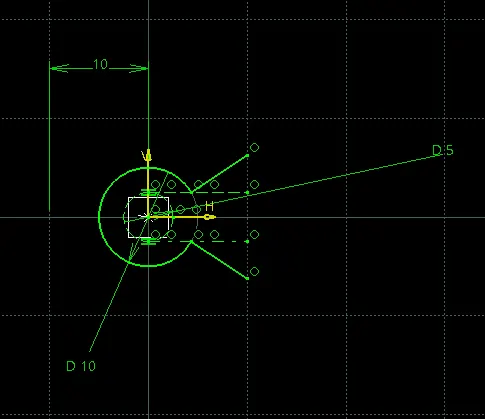
Create the Dog House for the Door Trim considering the design rules mentioned in the video. Consider the thickness of the part to be 2.5 mm.
"C" is where the doghouse contacts the backside of the surface
-
Doghouse wall thickness at the intersection of the part wall ( C ) should be 40% or less than the main wall stock ( T ).
-
The height of ( B ) should be between 3.0 – 6.0 mm
000
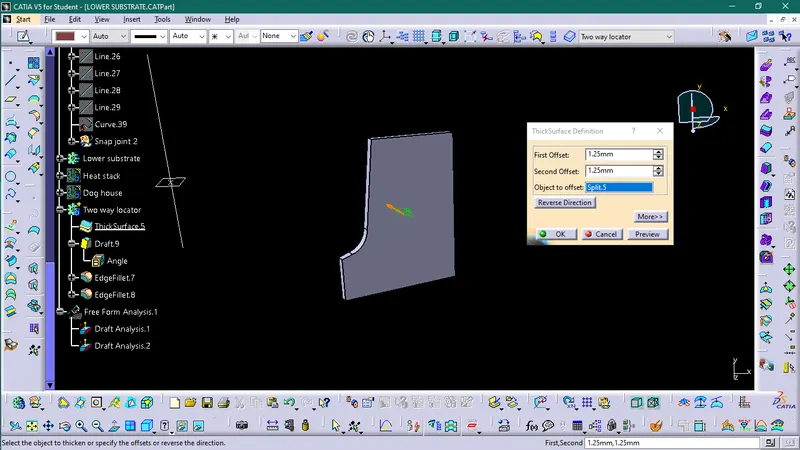
Two-way Locator
A 2-way locating pin restricts motion along 1 axis (or 2 degrees of Freedom), like a round pin in a slot. Likewise, a 4-way pin restricts 4 degrees of freedom along 2 axes. A round locating pin located concentrically in a hole is a common application of a 4-way pin and helps to further secure the piece
Snap Joint
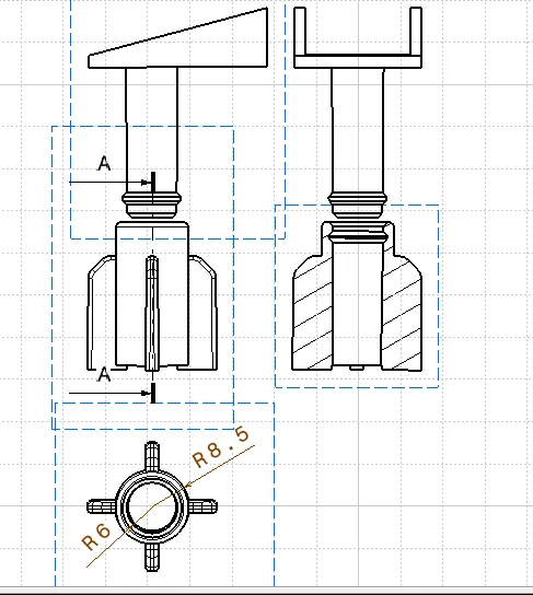
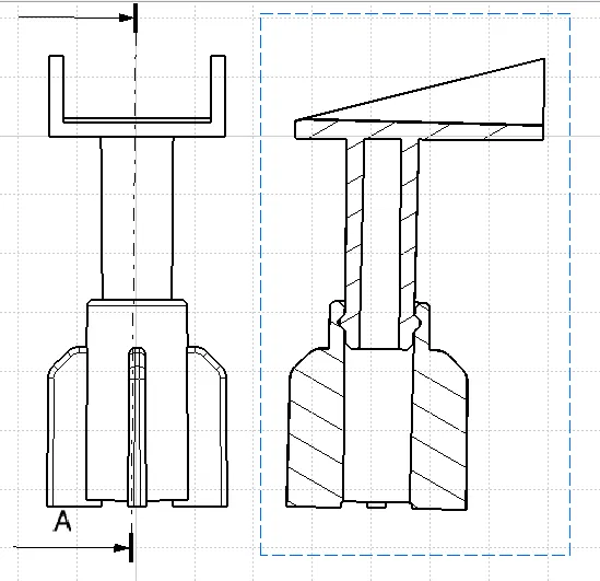
Snap joints are a very simple, economical, and rapid way of joining two different components. All types of snap joints have in common the principle that a protruding part of one component, e.g., a hook, stud, or bead is deflected briefly during the joining operation and catches in a depression (undercut) in the mating component. After the joining operation, the snap-fit features should return to a stress-free condition. The joint may be separable or inseparable depending on the shape of the undercut; the force required to separate the components varies greatly according to the design. It is particularly important to bear the following factors in mind when designing snap joints:
• Mechanical load during the assembly operation.
• Force required for assembly.
Types of snap joints
A wide range of design possibilities exists for snap joints. In view of their high level of flexibility, plastics are usually very suitable materials for this joining technique. The most important are:
• Cantilever snap joints:- The load here is mainly flexural.
• U-shaped snap joints:- A variation of the cantilever type.
• Torsion snap joints:- Shear stresses carry the load.
• Annular snap joints:- These are rotationally symmetrical and involve multiaxial stresses.
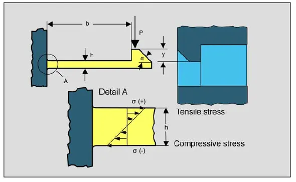
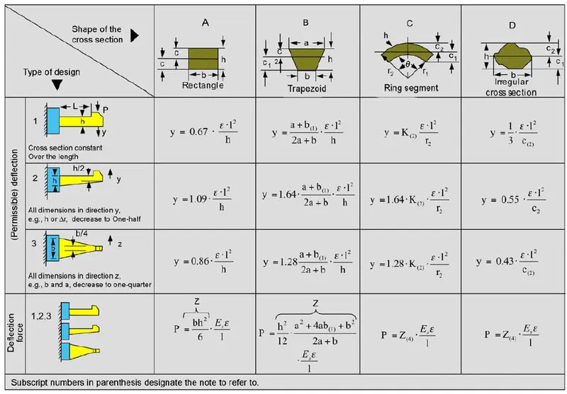
Cantilever Snap Joint
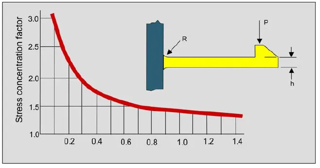
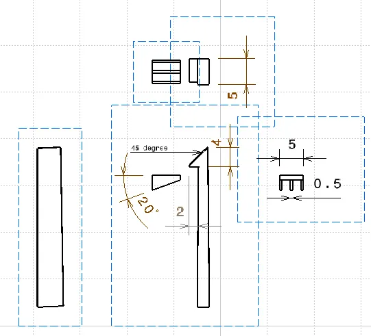
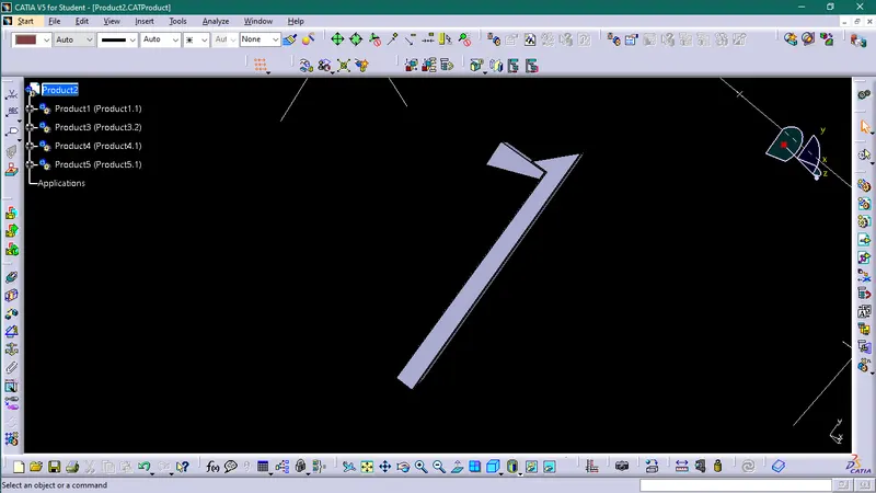
A large proportion of snap joints are basically simple cantilever snaps, which may be rectangular or of a geometrically more complex cross-section. It is suggested to design the finger so that either its thickness (h) or width (b) tapers from the root to the hook; in this way, the load-bearing cross-section at any point bears a more appropriate relation to the local load. The
the maximum strain on the material can therefore be reduced, and less material is needed.
Annular Snap Joint
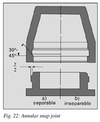
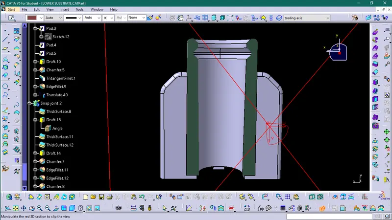
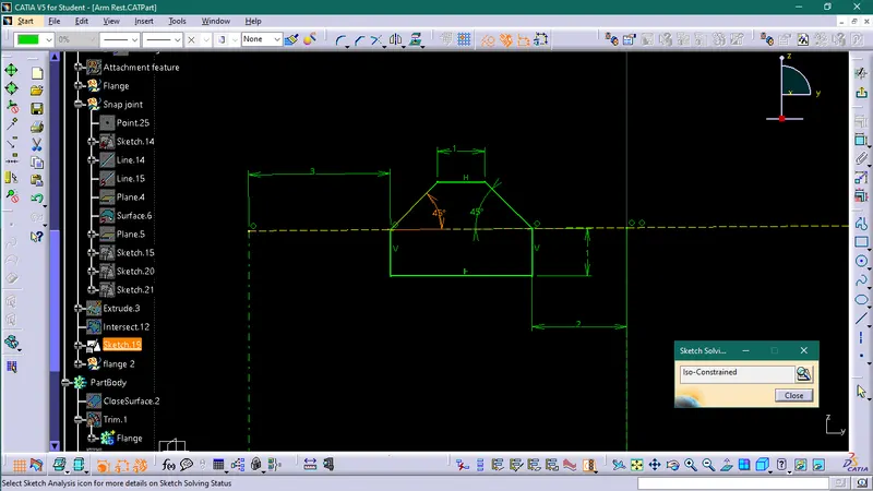
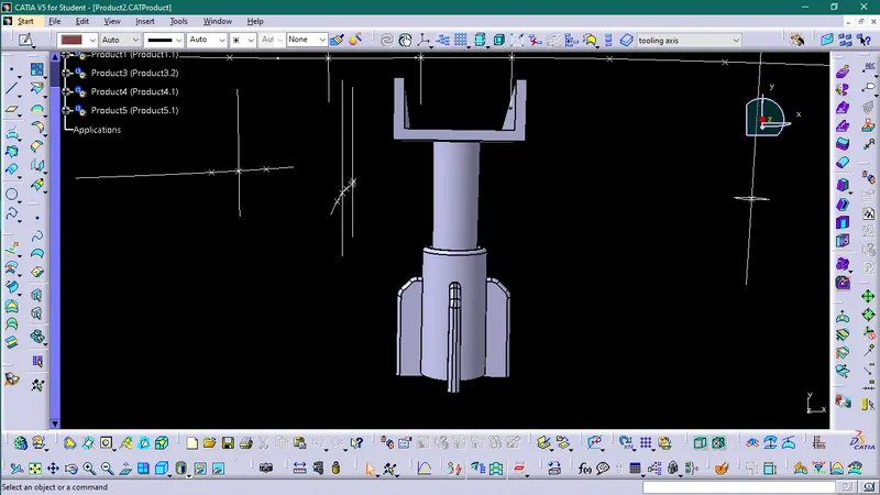
The annular snap joint is a convenient form of the joint between two rotationally symmetric parts. Here, too, a largely stress-free, positive joint is normally obtained. The joint can be
either detachable, difficult to disassemble, or inseparable depending on the dimension of the bead and the return angle. Inseparable designs should be avoided in view of the complex tooling required (split cavity mold). The allowable deformation should not be exceeded either during the ejection of the part from the mold or during the joining operation.
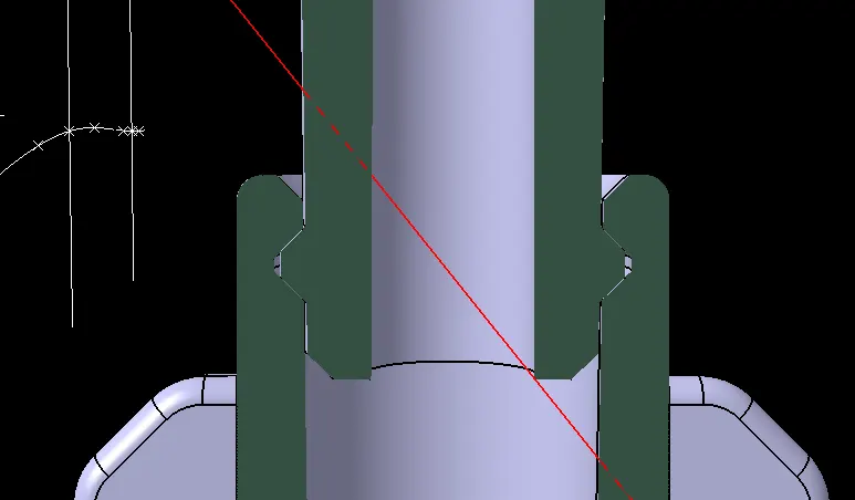
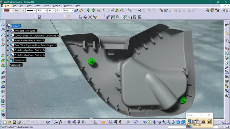
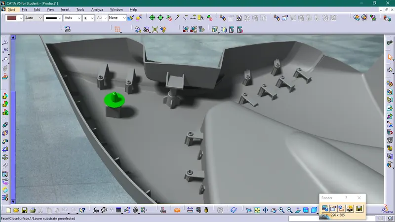
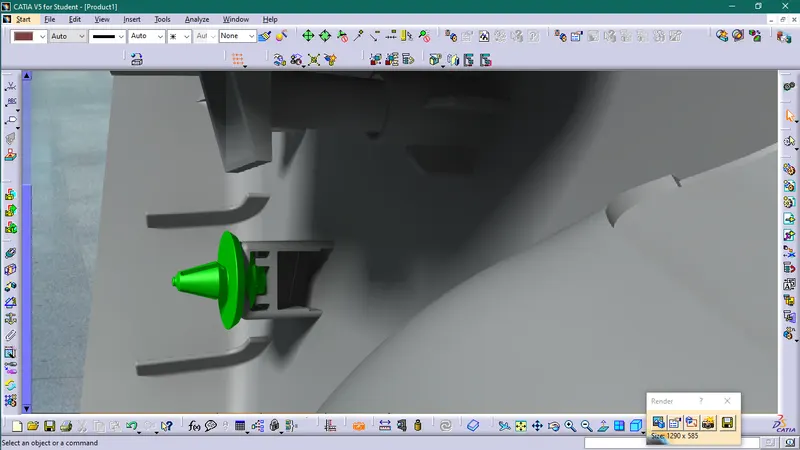
Push Pine
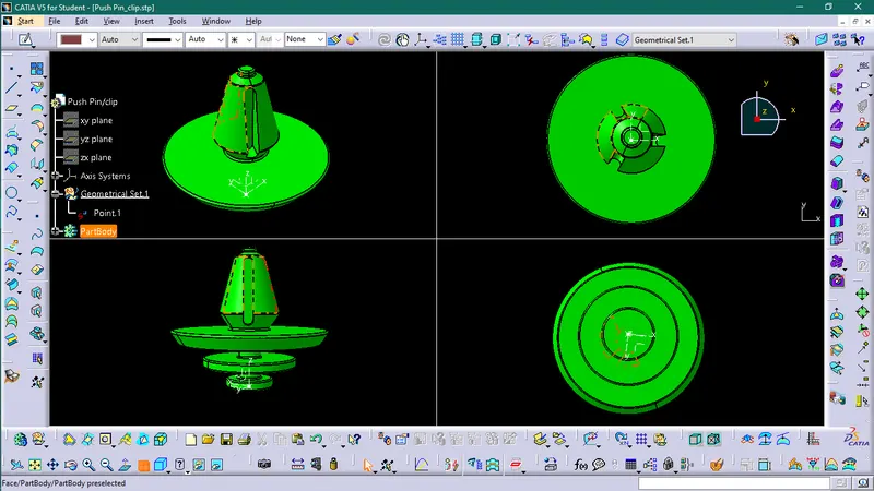
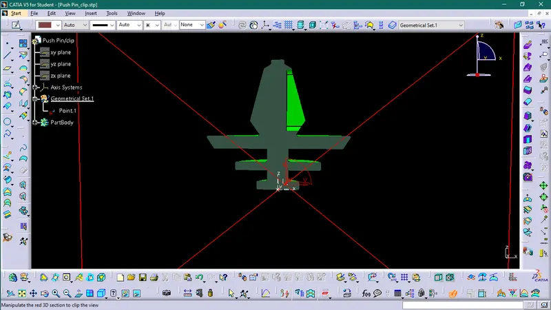
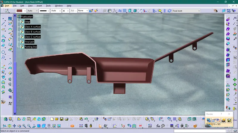
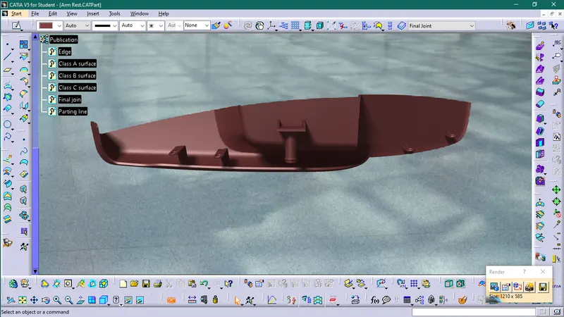
Arm Rest with Attachment Features
Draft Analysis
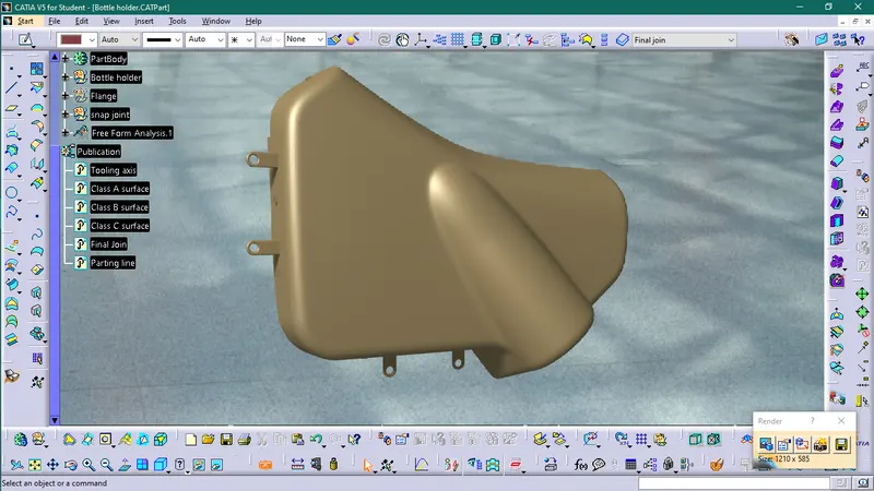
Bottler holder with Attachment Features
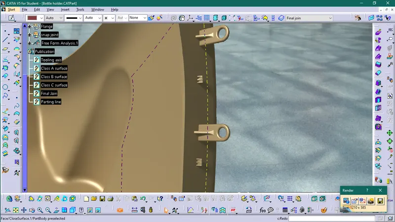
Draft Analysis
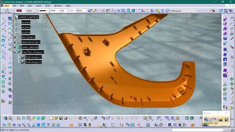
Lower Substrate with Attachment Features
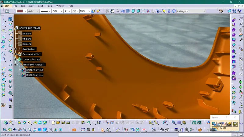
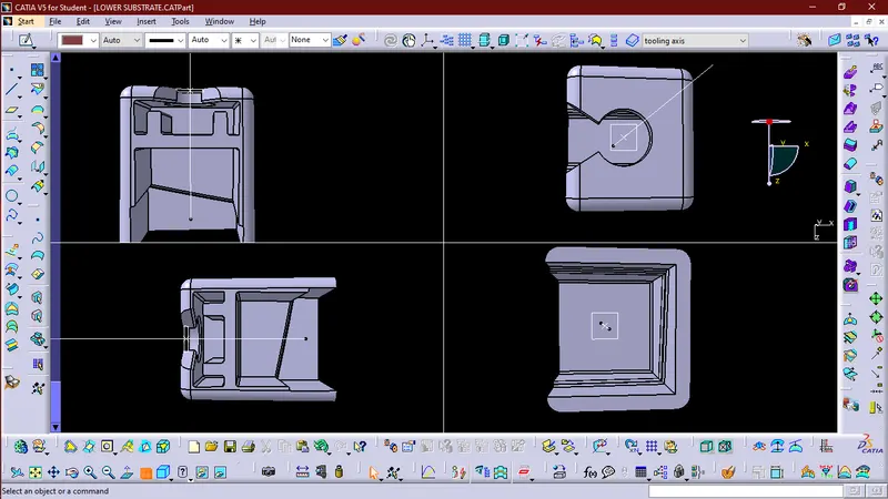
Draft Analysis
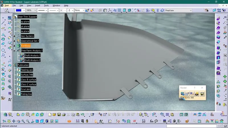
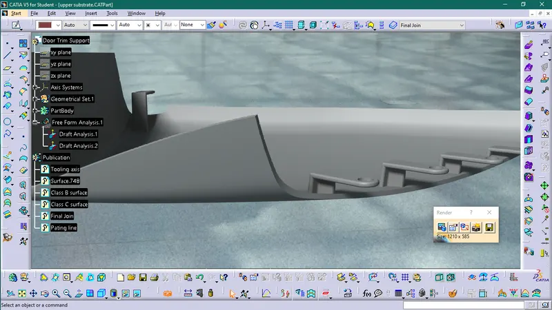
Upper Substrate with Attachment Features
Draft Analysis
Final Assemble