Week 11 - Final project
Aim
To create a Closed Surface and Assemble all the Solid Parts and installing B-Side features according to the Design Rules for given Class-A surface.
Introduction
The door panel will usually match the rest of the vehicle's interior. Door panels were formerly made of cardboard with an upholstered interior finish of vinyl, leather, cloth, carpet, or other materials for the decorative trim. Modern cars typically have door cards made of plastic, most often using injection molding, as well as incorporating other decorative materials.
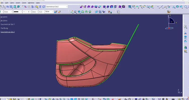
The Door Panel Consists of Arm Rest,Map Pocket,Lower Substrate and Bottle Holder Given Input for us.It also consists of Storage parts ,Lights and other components etc.
- The Given Input for us to work on is a Door trim
Procedure
- First we are going to convert the given Step file into Catpart.
- Then we are going to go with Bottom up approach which is dividing the Surfaces and working on each surface seperately.
- after dividing we will check the Class-A for any patches and then go for Class-B and Class-C.
- We will perform Draft analysis so that design is following the Design rules.
- After that we will create B-side features and Assemble all the solids together to get our final product.
Creation of Solids by Bottom-up Approach
Bottle Holder
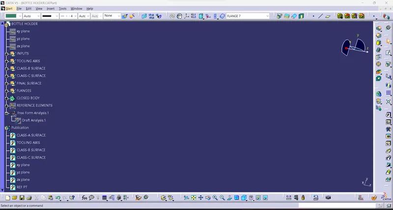
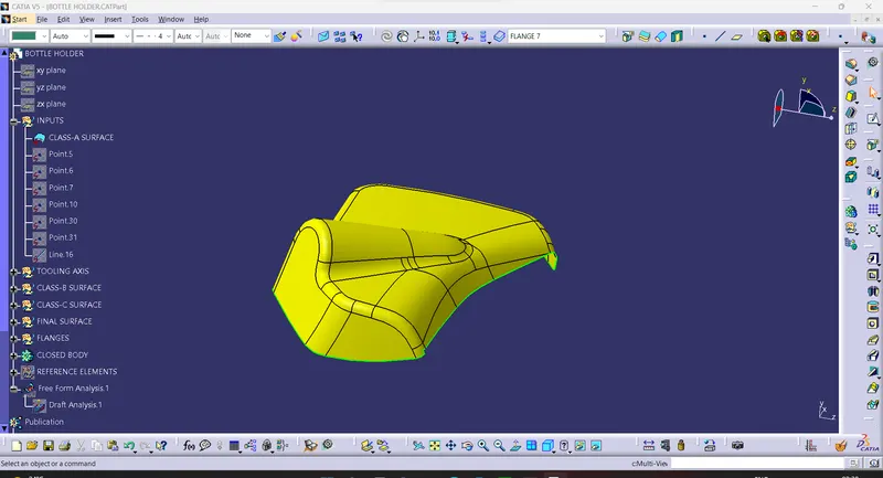
- First we are going to check the Given Class-A and find if there are any openings or patches.
- If there are no errors we can go to the next step i.e Finding the Tooling Axis.
- Given Class-A and we are giving color to the Surface so that we will not get Confused between Surface.
Tooling Axis
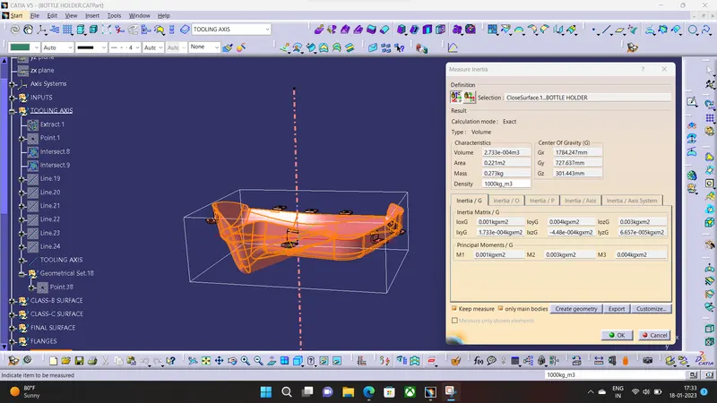
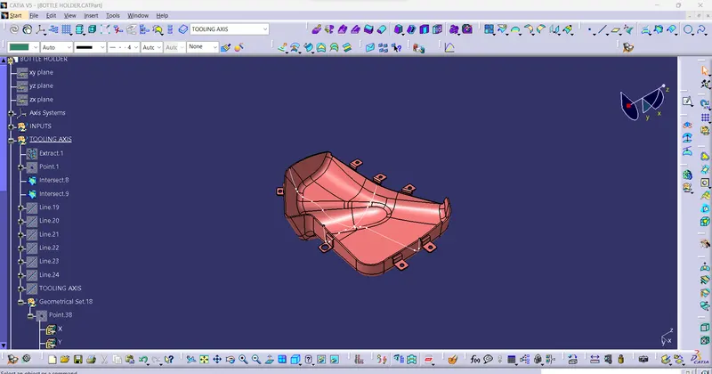
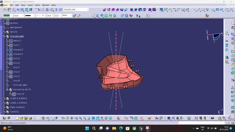
- For the Tooling we are going with the moment of inertia method and by selectinh the moment of inertia we can select Class-A surface and it will Create a Centre of gravity for the Surface.
- With this we can create a axis system and Create the Intersection in X and Z direction and then we can create a bi-secting line to create the Tooling Axis.
Draft analysis on Class-A surface
- We are going to perform Draft analysis on Class-A surface so that it clears our design rules.
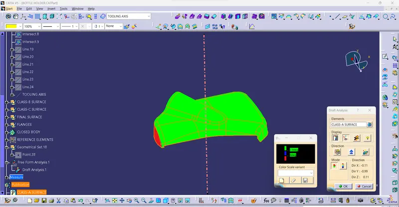
- Even though it clears the Draft some of the part is not clearing the Draft and we cannot change the Class-A as we Dont have the access to change the Class-A design and we will continue to do our Closed Surface.
Class-B surface
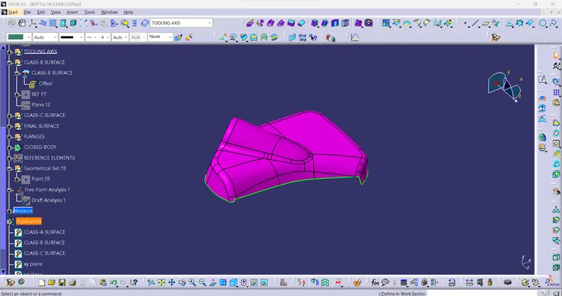
- For Class-B surface we are going to Offset The Whole Class-A surface to 2.5MM in outer Direction.
- We are going to solve if any patches are formed and then we will extrapolate the Boundaries of the Surface to get the Class-B surface.
Class-C surface
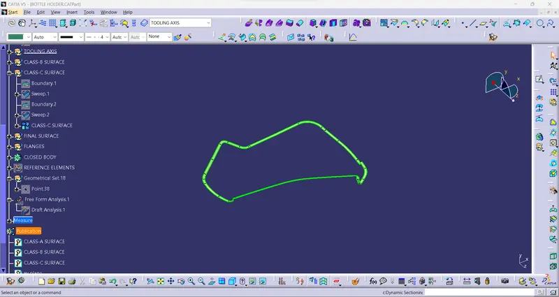
- For This surface We are Going to Need the Class-A surface. Mostly Boundaries of the Surface are used to create the Srface.
- Here as we can see that surface is perpendicular to the Tooling Axis and We are going with Sweep Along with Referance surface at 90°.
Final surface
- We are going to Join the Class-A and Class-c First and the Trim with Class-B surface to get the Final Surface.
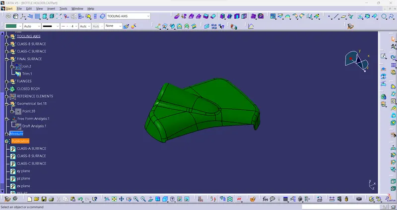
- Then we will check the surface is closed with Boundary command and then if there are no bounderies formed then our final surface is formed.
Closed Surface
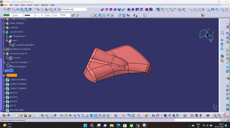
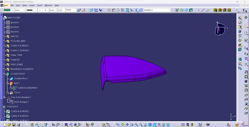
- After the Final surface is achieved we are going to give closed surface command to our final trimmed surface.
Draft analysis on the Closed Surface
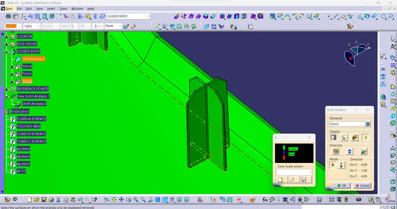
- We are going to perform the Draft analysis on the Closed surface as to see whether it is in our design rules or not .
- The Draft angle lies between 0°-3°.
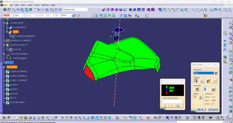
- This our Draft analysis and the red portion is negative draft but it is solved in reverse direction of draft analysis.
Map pocket
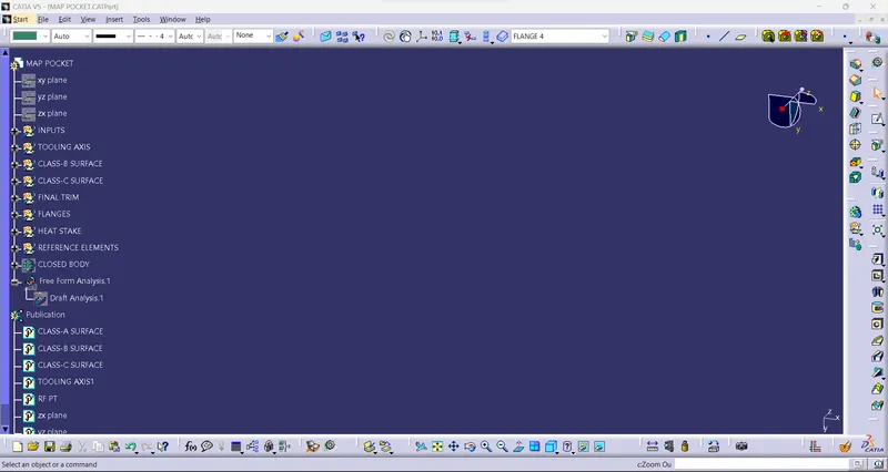
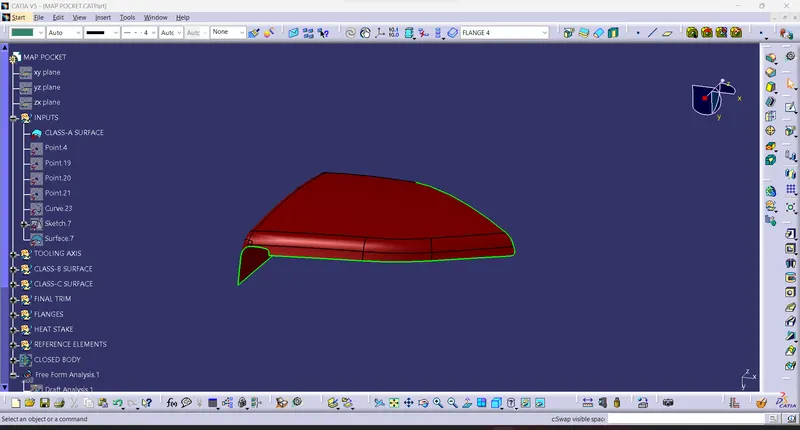
- We are going to check the Class-A surface and solve if there are any patches or boundaries.
Tooling axis
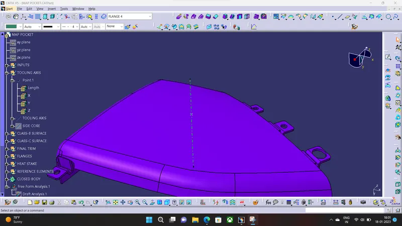
- We are going to extract the surface and create a point in the middle of the surface and then create line in Y- direction and this will be our tooling axis.
Draft analysis on class-A surface
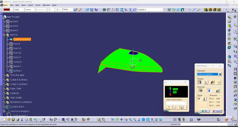
- We are to perform Draft analysis on the Class-A surface as to whether it is clearing our design Rules and Drfat between 0°-3°.
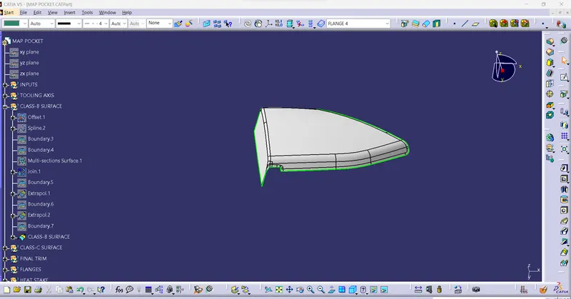
Class-B surface
- Class-B is obtained by Offsetting the Class-A surface to 2.5MM inside the Surface and the we will sove if there any patches formed and solve it by extracting and Trim and Join with Surface.
- After this we will Extrapolate the Boundaries of the Surface to Obtain the Class-B surface.
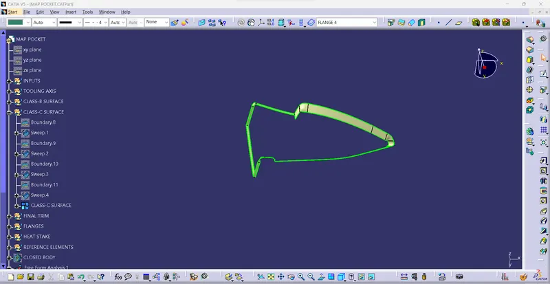
Class-C surface
- We will Use sweep with Reference Surface as The Surface is Perpendicular to Tooling Axis.
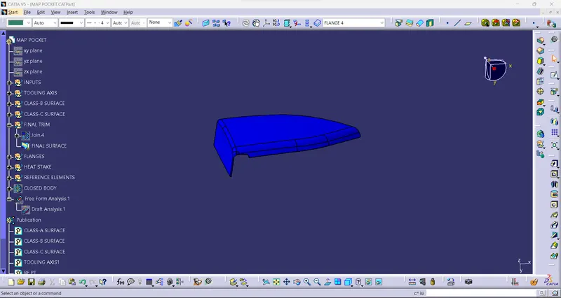
Final surface
- We will first join the Class-A and Class-C and then Trim it with Class-B surface to get the Final Surface.
Closed Surface
Draft analysis on Closed Surface
- We are going to perform the Draft analysis on the Closed surface as to see whether it is in our design rules or not .
- The Draft angle lies between 0°-3°.
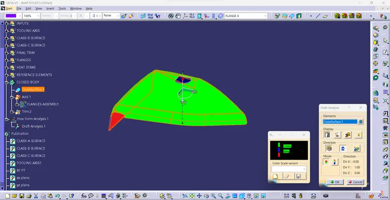
- The Body is Clearing our Draft Conditions.
Lower Substrate
- First we are going to check the Surace and then go for the tooling Axis.
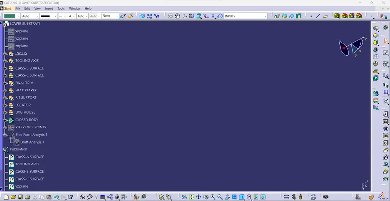
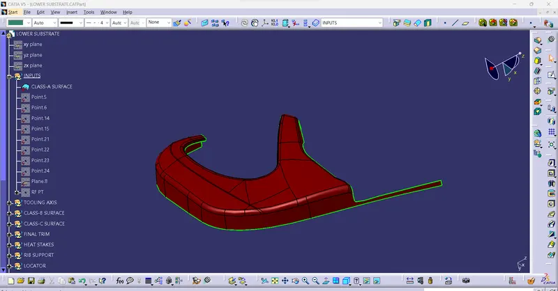
Tooling Axis
- We are going to extract a flat surface and create a middle point and create a line in Y-Direction and this will be our tooling Axis.
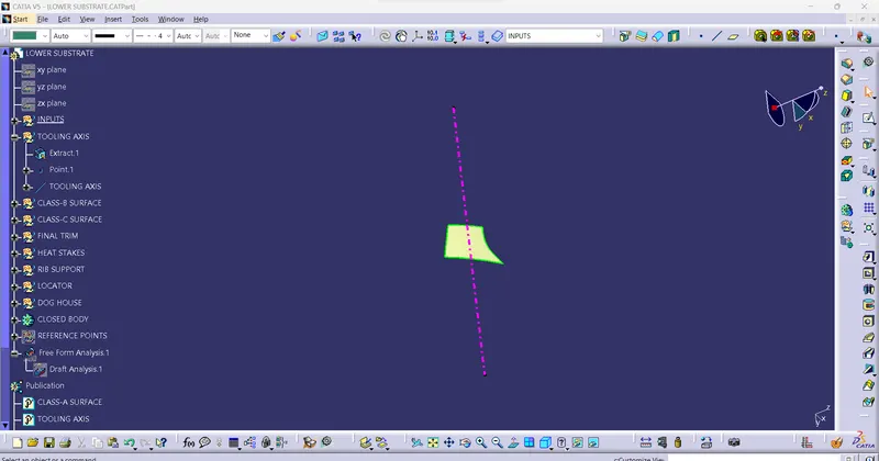
Draft analysis on Class-A surface
- We are going to Check the Class-A with Draft Analysis so that is within our Design Rules.
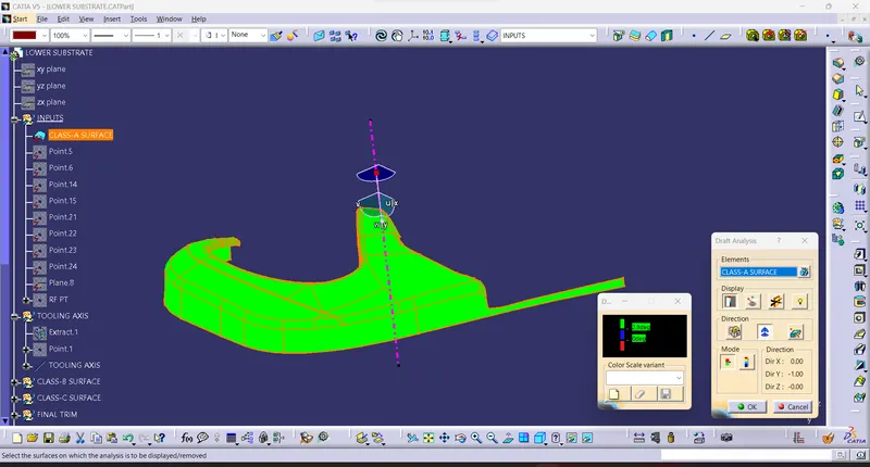
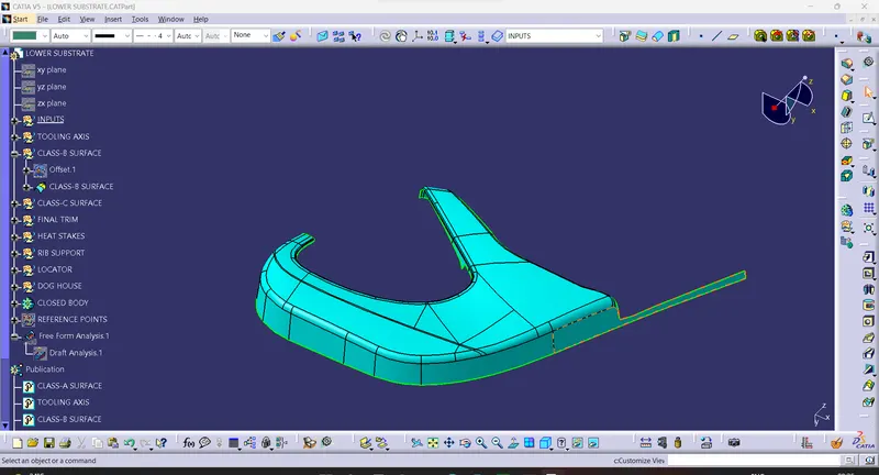
Class-B surface
- We are going to Offset The Class-A to 2.5MM inside The Surface.
- Then we are going to check if there are any patches formed on the surface and then extrapolate the boundaries.
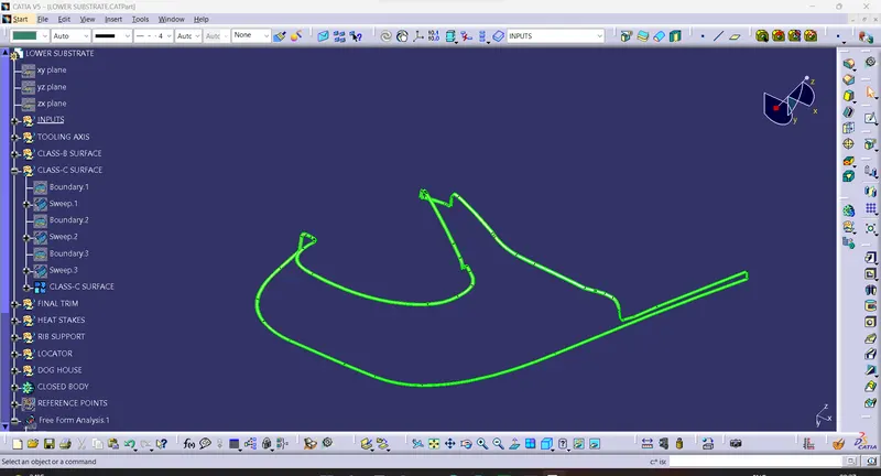
Class-C surface
- we are using Sweep with reference surface to create the Class-C surface as the Surface is perpendicular to Tooling Axis.
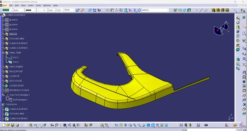
Final Surface
- We are going to join the Class-A and Class-C surface and Trim with Class-B surface to obtain the Final surface.
Closed Surface
- We are going to Closed surface on the Final surface to get the Solid part.
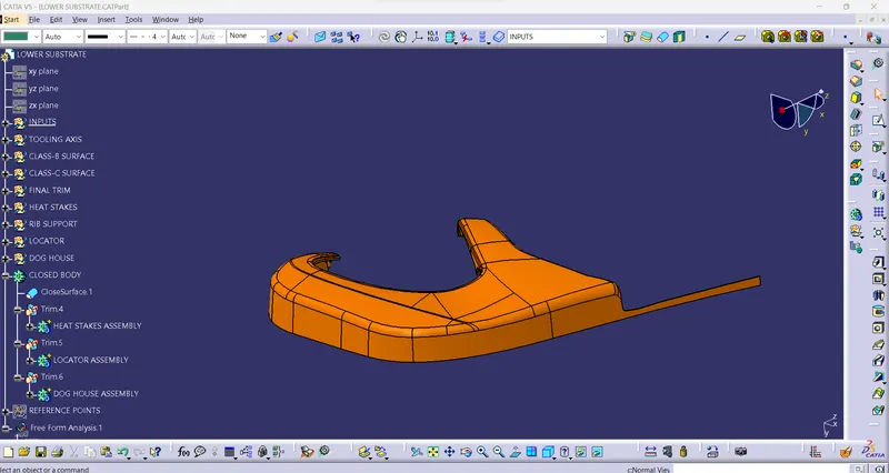
Draft analysis on Closed Surface
- Performing the draft analysis on the Closed body so that it will be in our Design rules range.
- draft angle should be between 0°-3°.
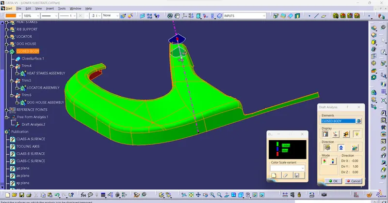
- The analysis is within our design rules.
Arm Rest
- First we are checking if there are any patches or boundaries in between the surface.
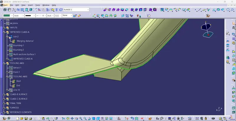
- There is a boundary gap we are goin to solve this by join command and then we are going to join the surface by creating multi sections and joining with the whole surface and then we will get our improved Class-A surface.
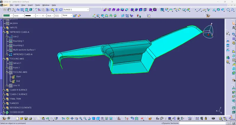
- After we get the Improved Class-A we will find the Tooling Axis.
Tooling Axis
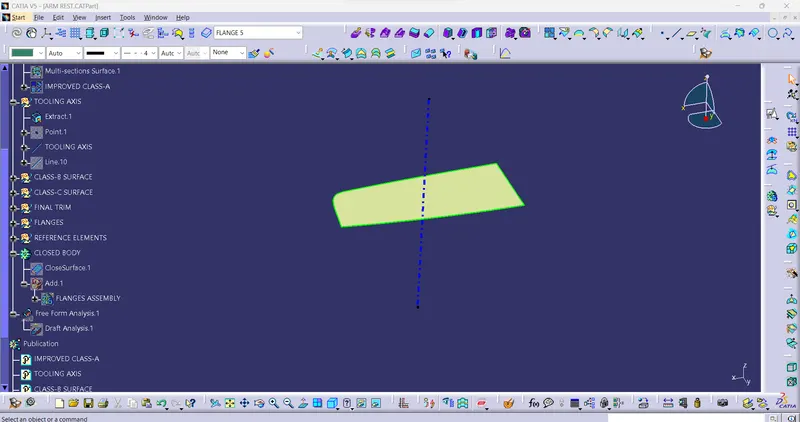
- For tooling we are going to extract the flat surface and create a point in the middle and then crate a line in Z-direction to get the Tooling Axis.
Draft analysis on Class-A surface
- We will perform Draft analysis on Class-A surface.
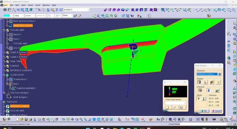
- As there are Some error in the Class-A we are not Clearing the Draft angle And we do not have the privilages to change the design of Class-A we are continuing with the given surface.
Class-B surface
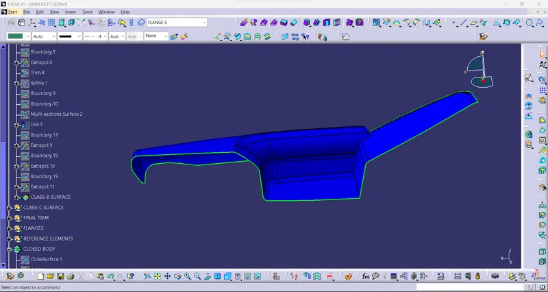
- We are going to offset the Improved Class-A surface to 2.5MM and we will get some patches .
- we will solve them by extracting the surface which are creating the problems and extrapolating them and trim with the surface to solve the patch.
- Then we are going to extrapolate the boundaries to get the Class-B surface.
Class-C surface
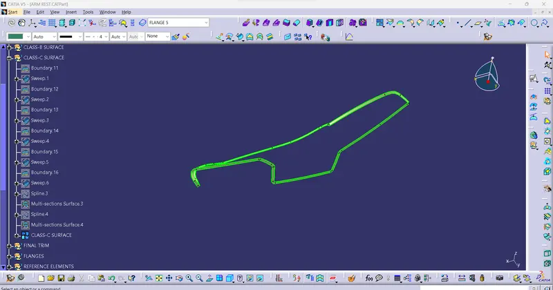
- we are goin to create the surface with Sweep with reference surface as the surface is perpendicular to tooling axis and join the Whole Surface to get the Class-C surface.
Final Surface
- First we will join with Class-A and Class-C surface and then Trim with Class-B surface to get final surface.
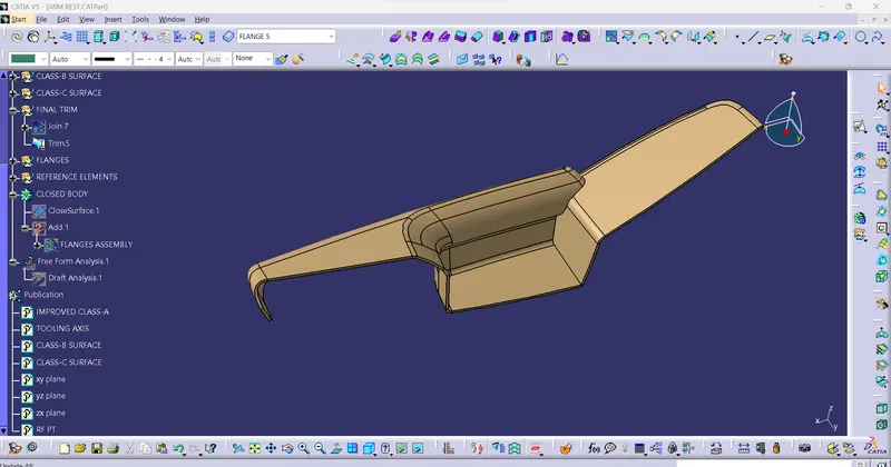
Closed Surface
- We are foing to give Closed Body to Final Surface.
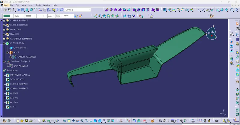
Draft analysis on Closed Surface
- We are going to perform the Draft analysis on the Closed surface as to see whether it is in our design rules or not .
- The Draft angle lies between 0°-3°.
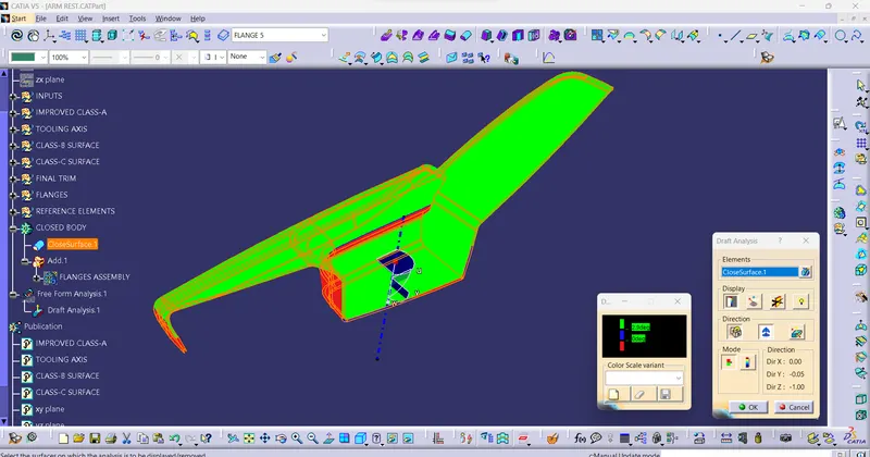
- Some of the parts are not Clearing the Draft angle as the problem is from the Class-A surface and Cleared part is in Bend shape as it is not viewable from the Tool Axis side and As we do not have the rights to modify the Class-A so we are Continuing with the given surface.
- The negative Draft is clearing in reverse direction.
Creation of B-Side Features
Dog House
- Dog house is an engineering feature used in the plastic trim design. Doghouses are used as supporting features. Sometimes other engineering features like snaps; locators, etc. are mounded on them to increase their strength. Dog houses are subjected to draft analysis to prevent breakage of the component during ejection from the mold cavity. Dog house and other engineering components are built on B-surface.
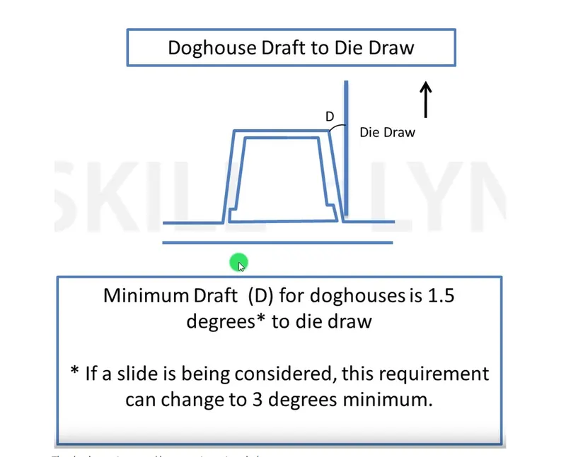
- The Dog house is required only on the Lower Substrate and so we are going to extrat the surface from the Final surface and not the Closed body as it may create errors.
- After extracting we are going to create a point at random place and then we are going to create the Dog house according to design rules.
- we are going to create a plane and create it with positioned sketch.
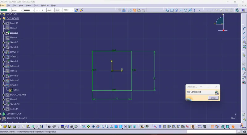
- First i create a Square of length and width of 25MM and then padded it to 30 MM as per the Design rules for creating the Dog house.
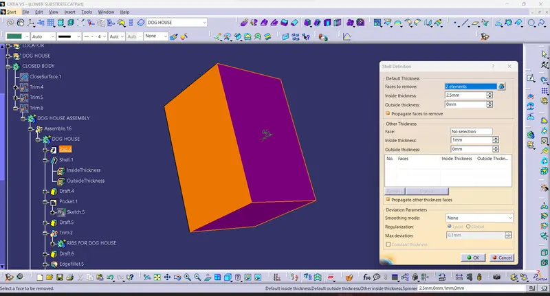
- After this i gave thickness command of 2.5MM
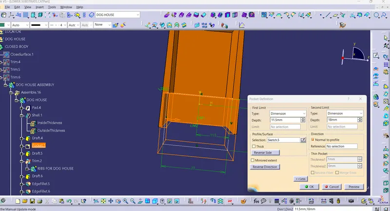
- After this we are going to create the thickness at the bottom by creating a rectangle and then using pocket command.
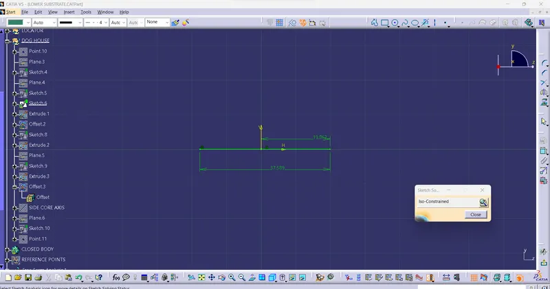
- for creating the ribs we are going to create a lin and extruding in X-direction and then offsetting to 20MM and then we will give thicness Command of 1.5MM.
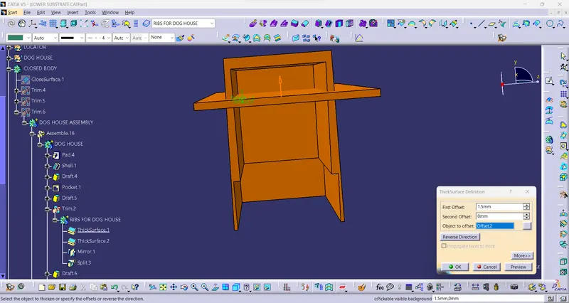
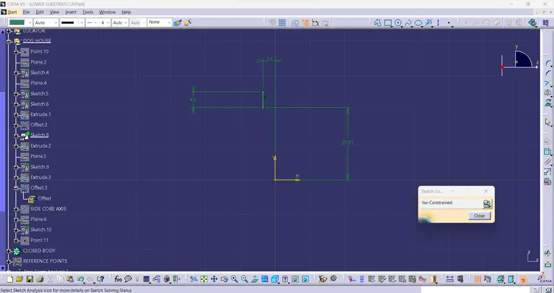
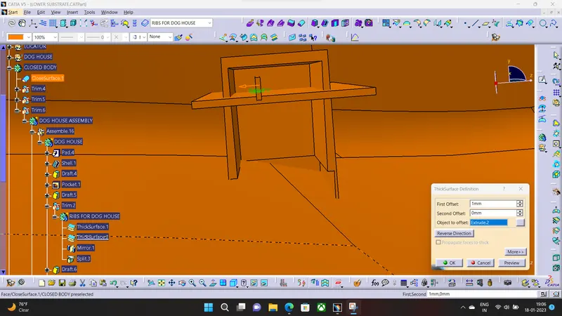
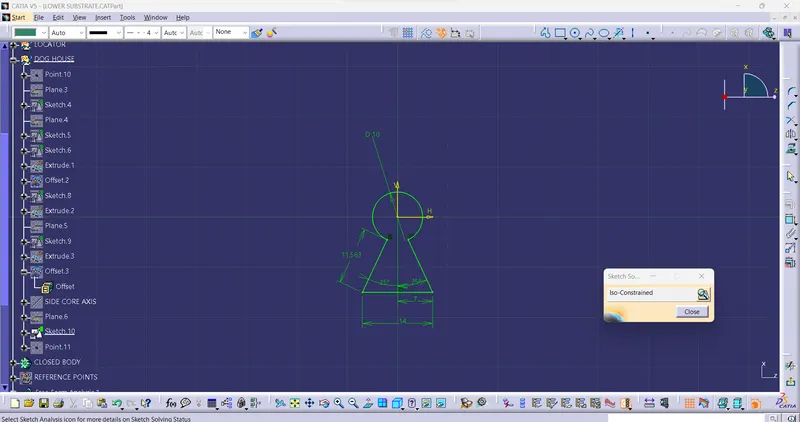
- After this we are going to mirror the Small rib and then Union trim it with Main Body and obtain the Dog house.
Draft analysis on the DogHouse
- We are going to perform draft anlysis on the Dog house outer part with Tooling Axis.
- The Draft angle is between 0°-1.5°
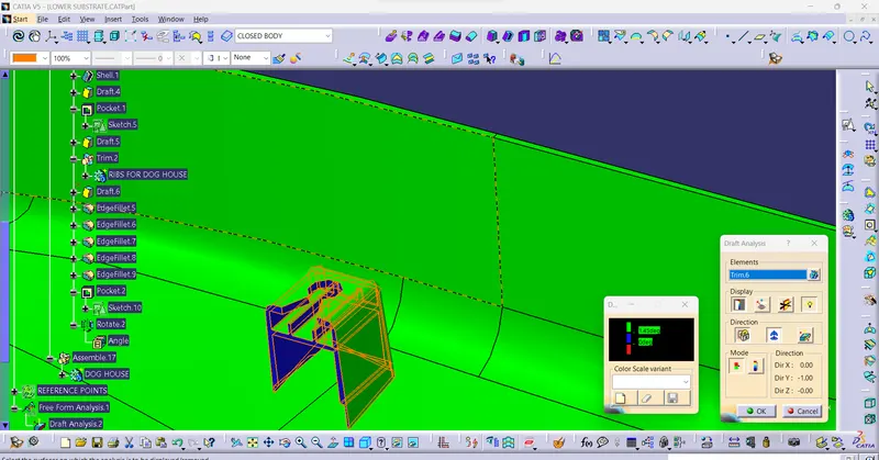
- The Outer part is within our Design Rules.
For the Inside part we are going to create a Side core Axis so that it Clears the Draft.
- The Draft angle is between 0-0.5°.
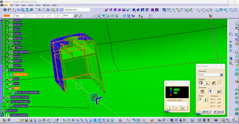
- The inside part is also within our Design Rules.
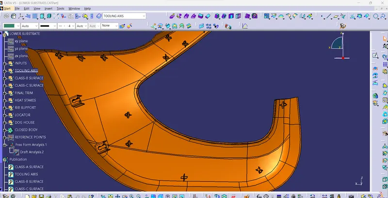
Heat Stakes
- In manufacturing products with thermoplastic components, it is often necessary to join a thermoplastic to a part of dissimilar material, whether it be metal, a dissimilar plastic, or other material.
- Thermal staking is an assembly method that uses the controlled melting and reforming of a plastic stud or boss to capture or lock another plastic or metal component of an assembly in place. The plastic stud protrudes through a hole in the component to be locked in place. The heated thermal tip contacts the top of the stud, which melts and fills the volume of the tip cavity to produce a head, locking the component in place.
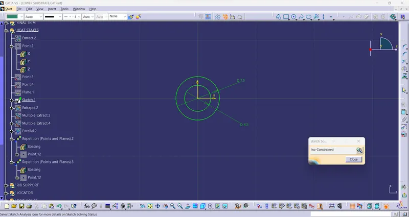
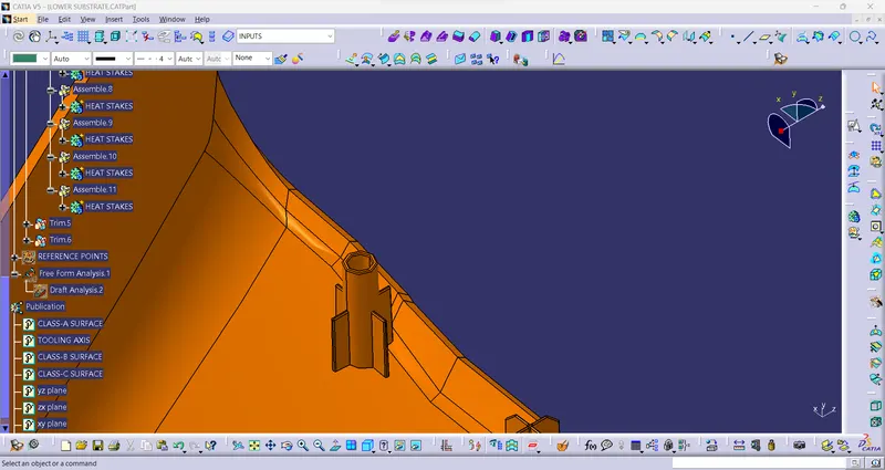
- Here i have create a heat stake of 7.5MM and Hole of 4.5MM according to Master sections and then Pad it to 25MM.
- After this we are going to Five Draft of 0.5°.
- After giving Draft we are going to create Rib support for the Heat stake.
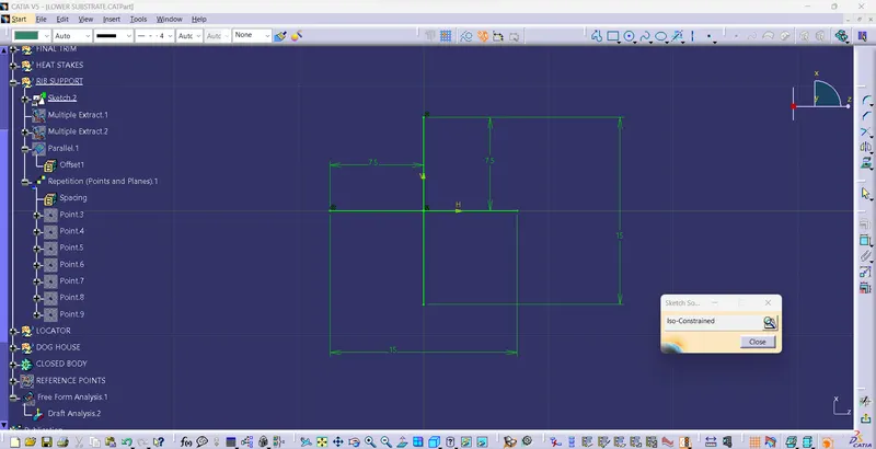
- Then we are going union trim the Rib with Heat stake.
Draft analysis on Heatstakes
- we will perform Draft analysis For heat stakes we will give a Draft of 0-0.5°.
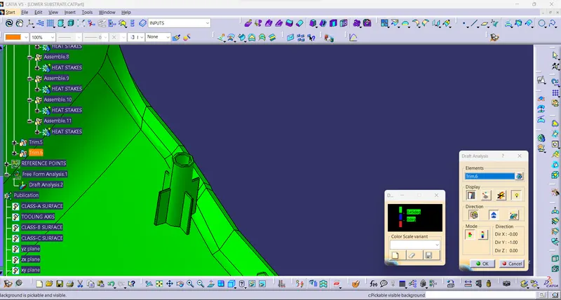
- The heat stake is within our Design Rules.
Locators
- Locators means you prevent movement or degrees of freedom on the plane. Generally, you have cylindrical pin on the fixture and circular hole at workpiece part.
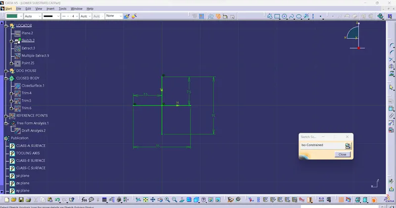
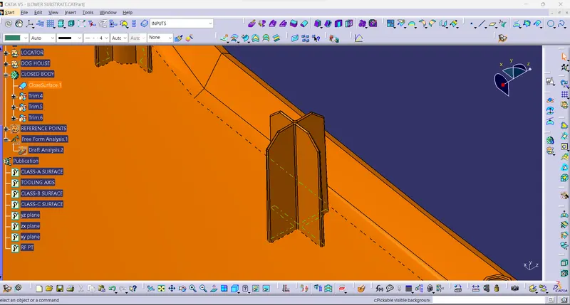
- As the Locators length Should be Greater than Heat stakes we are padding the Surface to 28MM and then we are giving Draft of 0.5°.
Draft analysis on Locators
- We will perform Draft analysis to check it is within our Design Conditions.
- Draft angle is 0°-0.5°.
Heat stakes and locators on Lower Substrate
Flanges
- Flanges are created for the assembly feature to attach with other Closed bodies and to avoid sink marks etc..
- For Creation of flanges we are creating it with reference to class-C surface so that it will align with Closed Body perfectly.
- We creating flanges on Map pocket,Bottle Holder and Arm rest.
- We are going to create it with reference to given Mastersections.
- First we are going to extract the Class-C surface of the Surface and Creating a plane and create intersection of the Surface.
- Then we are going to Coincide the Sketch with Intersection and then we are going to sweep with reference surface.
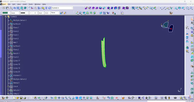
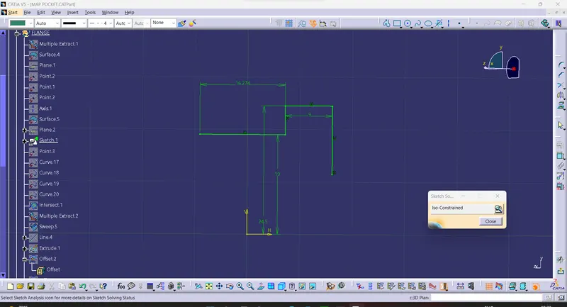
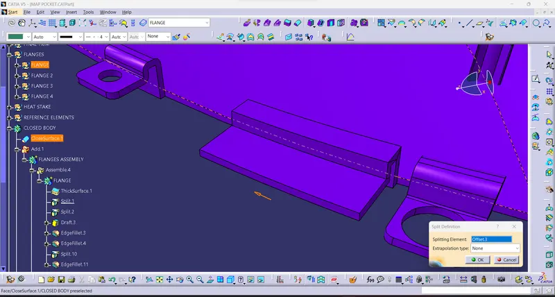
- After Sweep and Then we will create a Extrude in the Z direction and Split it to 10MM and we will get final Flange Surface and this how we create flanfes and we will give Draft of 0.5°.
- After this we are goinh to extract From heat stake the Circle and offset it to 0.5MM and then Split it with The Flange.
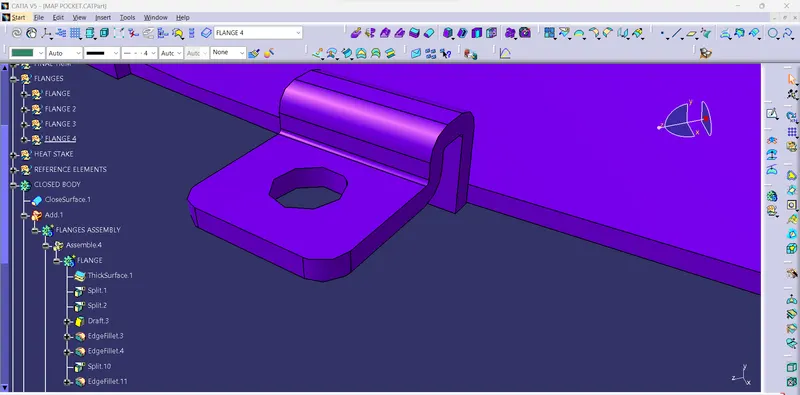
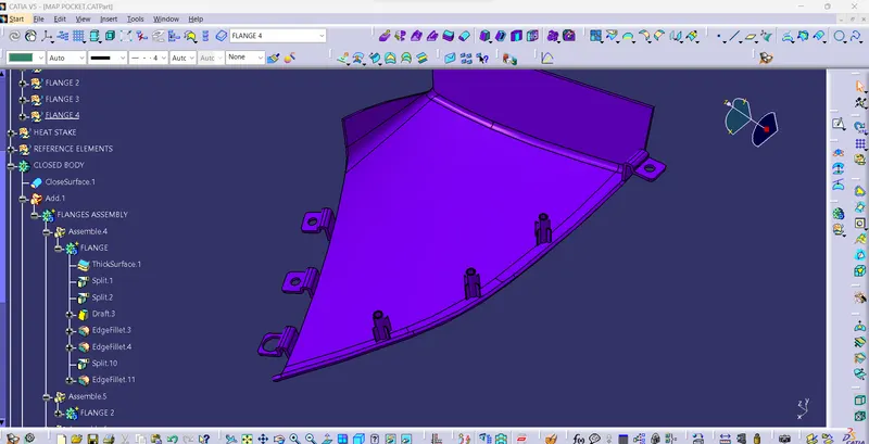
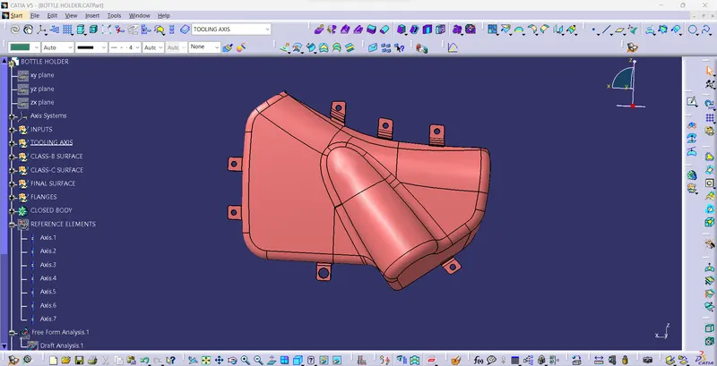
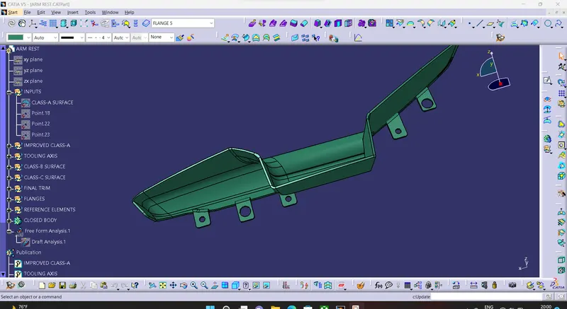
- After Creating the The Flanges and B-Side features we are going to Assemble All the Solid Parts together.
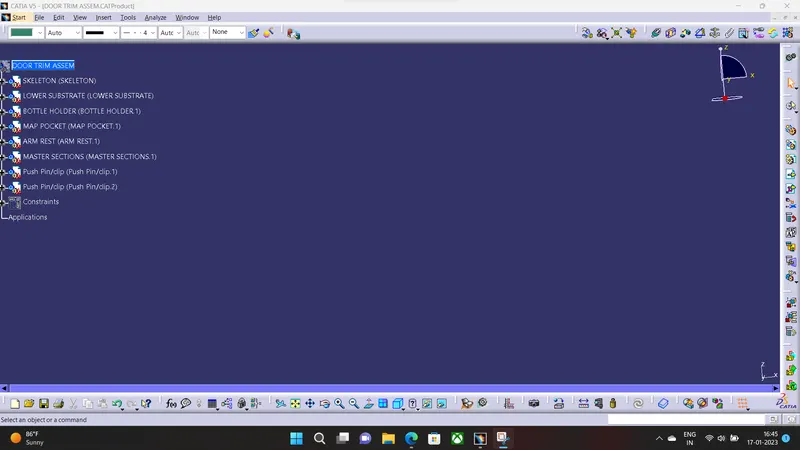
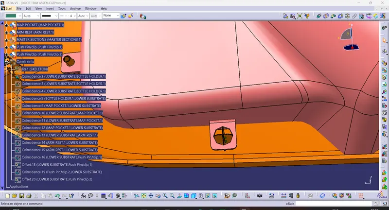
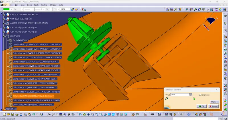
- For this we are going to open the Assembly workbench and we will give Constraints and Attach them.
- We are going to create axis on the flange holes and Coincide it with heat stakes Axis.
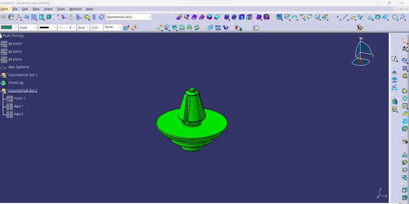
PushpinClip
- It is also a Fixation Part to attach with sheetmetal parts and it will be attached to dog house.
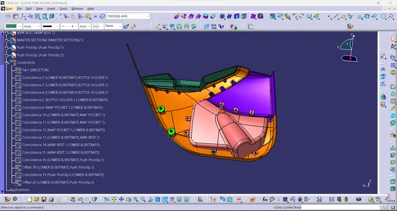
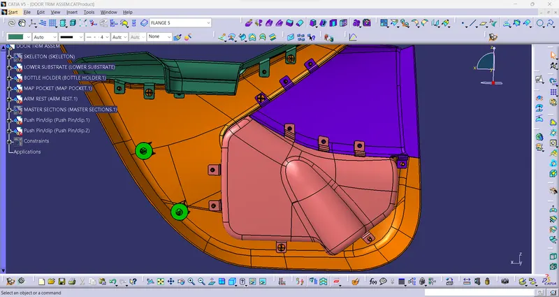
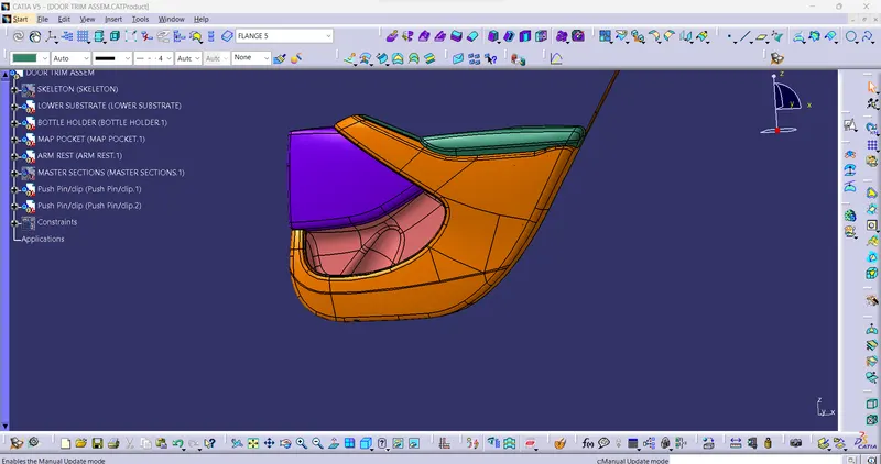
- After this the Whole Assembly will look like the below picture.
Conclusion
- Hence we have created a Solid Body for the Door trim and Created B-side features and Performed Draft analysis which is clearing our Design Specifcations.