Week 11 - Final project
- Development of aDOOR TRIM PANEL using CATIA- V5
Creation of CAD model considering following inputs as like in OEM and tier1 companies
- a) Class A surface
- b) Nominal thickness : Refer master sections
- c) Attachment strategy :
Find a attachment strategy for the door panel complete work.
Use Push pin with Dog house for Lower substrate – Door panel attachment
Use heat stakes for part to part attachment
Output required:
- Create thickened part using master section for reference
- Create the mounting features as per design guidelines in the industry and with master sections
- Apply material details :
- Draft analysis & Tooling analysis
- Creation of parting lines and check tooling feasibility
Output required in attachment
- Submit the CATpart and CATproduct in the attachment
Project Overview:
Door Trim is the interior component attached to the interior side of the door. It's a vital component which provides aesthetic look to the interior of the car and also provides features and functions for the passengers. In this project we are going to design the lower portion of the door trim from the given Class-A Surface. Also we would be designing the B-Side Features on the component by following the industry standards and design rules.
INTRODUCTION:-
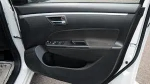
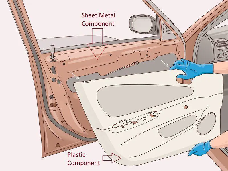
Side Door Plastic Trim
An interior plastic component attached to the inner side of the door. This product improves the appearance of the vehicle intertior and also creates a more comfortable interior by providing a variety of fitments and functions.
Manufacturing Process:
Injection Moulding:
Injection moulding is one of the most commonly used production processes for plastics. It offers a viable solution for the mass production of high-quality injection automotive parts from a broad range of polymers. In the automotive industry, where consistency, safety, and quality are of utmost importance, automotive plastic injection moulding is an important manufacturing process.
Plastic injection moulding is the process of melting plastic pellets that once malleable enough, are injected at pressure into a mould cavity, which fills and solidifies to produce the final product.
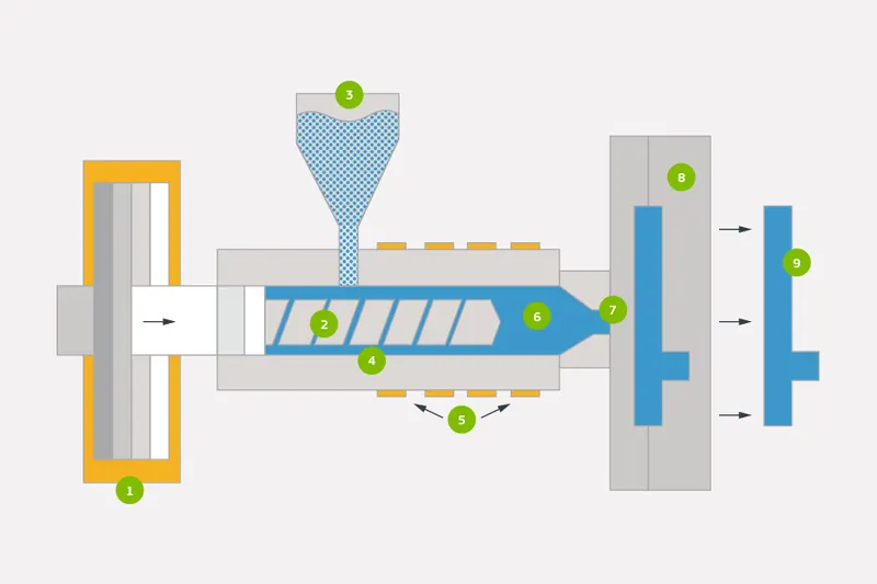
From left to right, the components of a rapid injection moulding press include ram (1), screw (2), hopper (3), barrel (4), heaters (5), materials (6), nozzle (7), mould (8), and part (9).
Workbench and its Toolbar used:
Generative Shape Design Workbench
- Surface Toolbar
- Wireframe Toolbar
- Operation Toolbar
Part Workbench
- Sketch Based Feature Toolbar
- Dress up Features Toolbar
- Surface Based Feature Toolbar
Assembly Workbench
- Constraints (Coincidence ,contact, angle offset)
- Assembly features
- move
- Product Structure Tools
INTRODUCTION
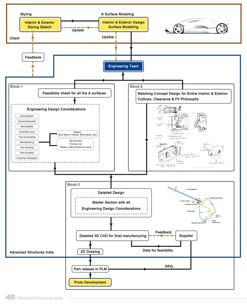
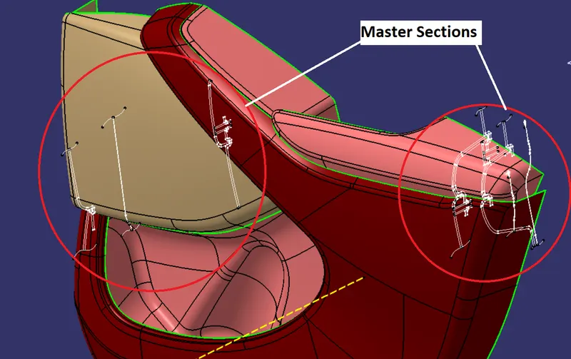
MASTER SECTION: Master sections development takes place during feasibility check and concept validation stages of the product life cycle. These are typically the guides for design requirements and which decides the component packaging after the development of the concept design, i.e class A surfaces.
Master section helps us to decide the feasibility of the concept design, the clearances, the packaging and the fixation strategy of a component before converting the concept design into a solid 3D engineering design.
During the period of vehicle concept design, the evaluation of the master section performance depends mainly on the reference vehicle data and the experience of the structural design engineer.
DESIGNING METHODOLOGY:
IMPROVING THE CLASS A SURFACE
The given class A surface is not a proper surface for Door Arm Rest because it is lacking the side Fillets so first thing that we have to do is to remove smaller Fillet from Class A surface Brcause it is not possible to take offset of it in B surface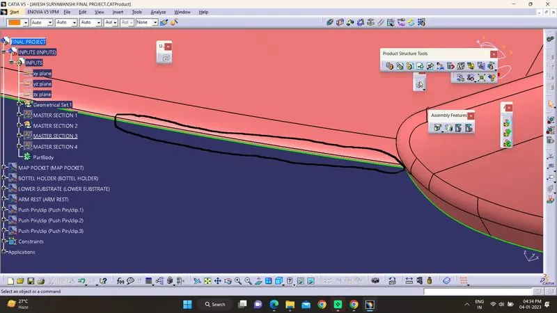 surface.
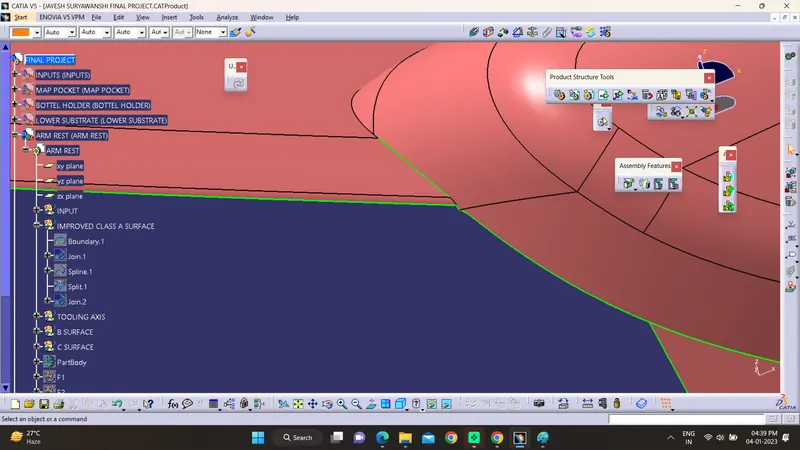
also we are haveing some open Boundries in Given Input Class A surface
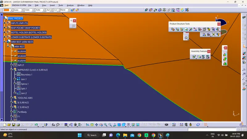
Also We are removing sharp corner from class a surface by Splliting Command.
Steps followed
- The class A surface is checked for the connectivity of the surface and ensure it is completely joined and there will be no gap between the surfaces.
- If it is not join together make it with a minimum tolerance of 0.001 to 0.003 and check for connectivity of the surface.
- Connectivity of the surface can be done by two ways by join method and by boundary method.
- Split the surfaces into multiple profiles then Identify the surface where it is not possible to create a tooling axis by following the minimum draft angle and check on which direction is best fit for tooling axis and then define the tooling axis and draft direction.
- Here for defining the tooling axis first we have created a point at middle of the base surface and create an axis with respect to that point then define the tooling axis using the intersect method by creating a bisecting line.
- Then do a draft analysis on the class A surface and identify the draft angle then give the nominal value for the draft.
Tooling Direction
Tooling direction is the direction the mould takes to make the part. It is basically the direction that the mould pulls apart. The mould is built in two separate pieces, a cavity side and the core side. The core pulls apart from the cavity and that is the Tooling Direction.
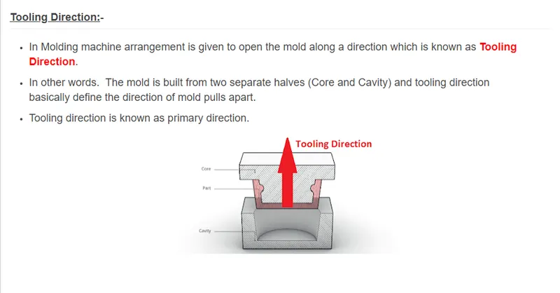
Core is the male part which forms the internal shape of the moulding. Cavity is the female part that forms the external shape of moulding.
Parting line is the line of separation on the plastic part where the two halves of the plastic injection mould meet, i.e. where the core and cavity meet.
Design for Manufacturing & Assembly (DFMA)
Design for Manufacturing and Assembly is an engineering methodology that focuses on reducing time-to-market and total production costs by prioritizing both the ease of manufacture for the product’s parts and the simplified assembly of those parts into the final product – all during the early design phases of the product lifecycle.
Before becoming the singular philosophy it's known as today, DFMA used to be considered as two distinct methodologies: Design for Manufacturing (DFM) and Design for Assembly (DFA).
DFM is concerned with selecting cost-effective raw materials and attempting to minimize the complexity of manufacturing operations during the product design phase in order to reduce the overall manufacturing time and costs for product components. Similarly, DFA is concerned with reducing the product's assembly time, costs, and complexities by minimizing the number of individual parts, assembly steps, and the potential for variability in build quality.
Function of Heat Stake, Locator, Doghouse, and Ribs
Heat staking technology is quite simple in concept. Whenever two or more components need to be attached to one another, and at least one is made of a thermoplastic, a combination of heat and pressure can be used to reform the plastic to the many shapes or profiles to retain or join the parts together.
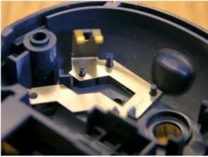
Heat Stake (cylindrical structure on the left)
A 2-way locating pin restricts motion along 1 axis (or 2 degrees of Freedom). Likewise, a 4-way pin restricts 4 degrees of freedom along 2 axes.
Dog house is a 4 sided box attached to a flat surface which usually requires a riser/slider to mould. In other words, it has 3 sides and a roof, where the roof usually has a hole for attachment purposes.”
Ribs can be added to parts to add rigidity or stiffness. Adding ribs allows for a part to increase strength and bear a higher load.
Tooling axis creation
- The direction in which the mould open and closes is called the tooling axis direction.
- Check the connectivity of the surface and ensure there will be no gap between the surfaces and then define the tooling axis.
- While creating a tooling axis please ensure to give the tooling axis on a flat length surface or the surface which have a hole on it.
- Create a point on the middle of the base surface by using point on the surface command then create a intersection for the surface and extract the reference lines which will be helpful for creating the dummy tooling axis using the intersect method by creating a bisecting line..
- Use the line command and draw the lines which is aligned with the extracted lines and extended it to the required length.
Bisecting method
- Identify on which plane we have to do more operations and create the plane or axis on the component area define it on the dummy tooling axis direction.
- Intersect the class A surface with that plane then we will get a intersection sketch. Look for the profile (inclined line) which will create a problem and extract it then extending it by using line command.
- Then create a bisecting lines with reference to the lines we have extended and this will be our main tooling axis.
- In this case we have created tooling axis along with Y direction with reference to the base surface.
But in Our Project We Created Tooling Axis By Extracting The Surface and Drawing line by POINT - DIRECTION
Draft analysis
- Draft allows for the component to release from the mould, most parts or applications require a minimum of 0.5 to 1 degree draft angle and 3 dgree draft angle is widely used as per the norm.
- Change the material mode to customize mode before moving to the draft analysis.
- Insert –analysis-feature draft analysis
- Defining the draft direction Select draft analysis from the tool bar and click on the compass symbol and pull the compass from the right side top corner of the workbench and place it on the component where want to do the draft analysis. ‘W’ of the compass and tooling axis should be aligned on the same line.
- Once the compass is aligned with the tooling axis click on the lock symbol and drag on the surface we will get a wrong mark then select that point a table will appear it shows the draft value on the table we can adjust the draft value and analysis it for all the edges and surfaces.
- By clicking the on the surface and using the flipping tool we can assign the Flipping direction, the color of the surface change as per the flipping direction .
- Analysis under running point and move the mouse on the surface and it will show the details of the surface deg direct at each and every point of the surface.
Pre requisites before creating the tooling axis and performing draft analysis-
- Ensure that the Class A surface imported should be a single surface.
- This can be checked using the Boundary tool in the Operation Toolbar.
- If the surfaces are disassembled, join them using Join command which is also found in the Operation toolbar.
Creating any component from Class A Surface ( Overview ) -
- Decide a suitable tooling axis direction and create the Tooling Axis.
- Perform Draft analysis for analyzing whether the drafts on the component follow the industry standards.
- Create another surface ( B Surface ) offset to the Class-A Surface. The offset distance should be equal to the thickness of the component.
- Create a C- Surface ‘Sweeping’ the boundary of Class-A -Surface along the Tooling Axis.
- Trim Class- A surface with B-Surface and C Surface to create a closed surface.
- Finally create the solid part from this surface to obtain the desired component.
Procedure:
I] Visual Analysis of Class-A Surfaces:
Firstly we observe the Class-A Surface and understand how the component can be manufactured.
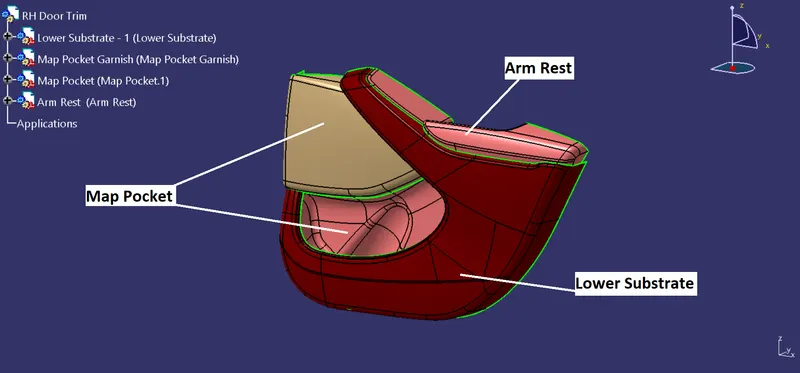
Observing the Master Sections:
The procedure of Draft Analysis is as follows-
- Before starting the draft analysis ensure that the ‘Materials’ option is selected under Customize View Parameters in order to view the results of the analysis.
- Click on Insert >> Analysis >> Feature Draft Analysis.
- Draft analysis window will be opened having three sections - Mode , Display and Direction.
- In the Display section select the compass and drag it onto your component. Place it along the tooling axis.
- Lock the direction of the draft.
- Another window will be displaying ranges of draft on the component. The ranges are - Green for more than zero , Red for zero and Blue for negative draft value.
- Assign the lower limit as 3 deg to the Green range from the value edition dialogue box.
- Once you do it, click on the component to see the results.
- You can also check the draft value at any point using the ‘Analysis under running point' option in the Display Section.
MINIMUM DRAFT FOR THE COMPONENT = 3 DEG
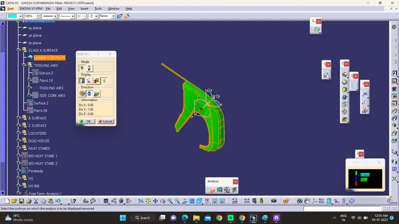
DRAFT ANALYSIS ON CLASS A SURFACE
LOWER SUBSTRATE
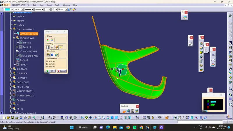
ARM REST WITH MAIN TOOLING AXIS
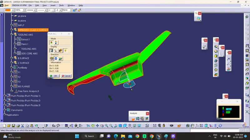
SOME PATCHES ARE NOT CLEARING
WITH SIDE CORE AXIS
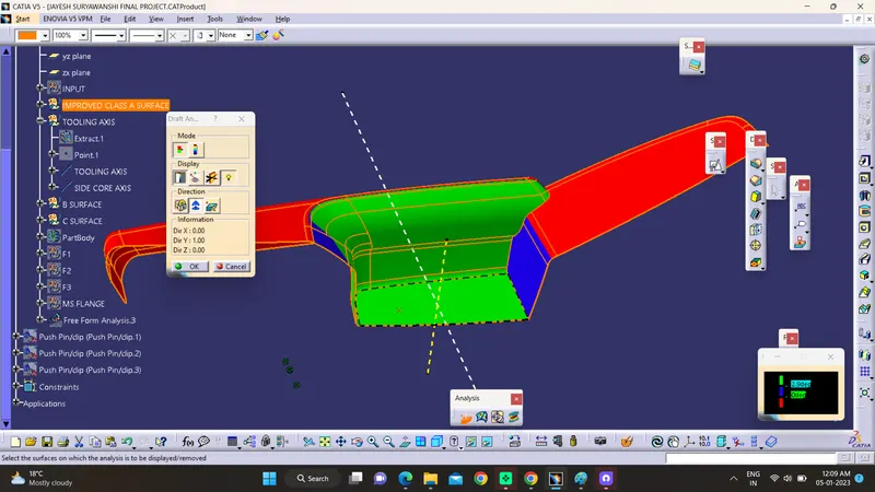
BOTTLE HOLDER
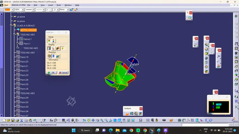
MAP POCKET
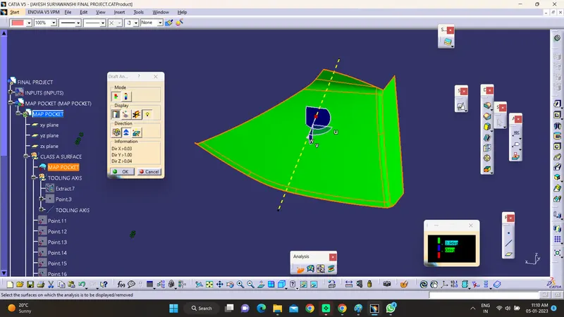
Here ,Now we are going to develope the CLOSED BODY from provided Inputs and Master Section of Door Panel.....
Designing the Solid Component from Class-A:
NOTE: The representation below of the steps mentioned above are for the Lower Substrate only. Similar steps were performed for designing other components
Class-A Surface:
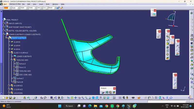
B Surface
offsetting class A surface 2.5mm in correct direction and worked on some patches which not offsetted
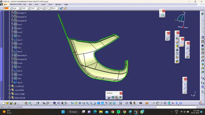
C Surface
by using sweep command with reference to surface and tooling axis direction we created the c surface and then by joining the class A surface with sweep we created and then trimming it with b surface we got closed body
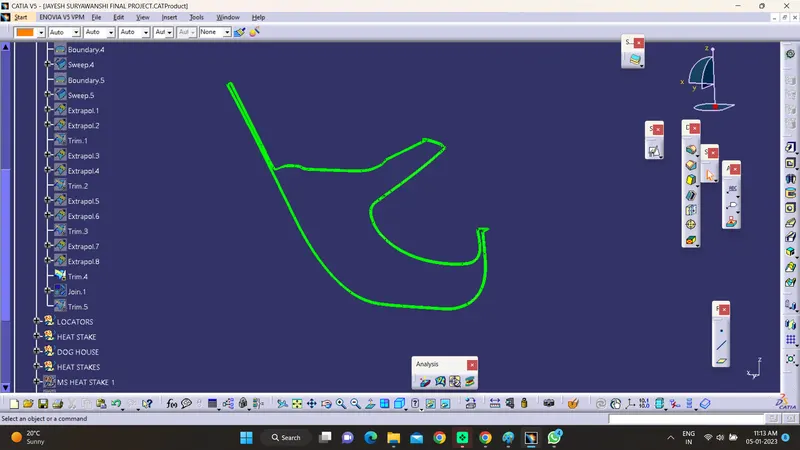
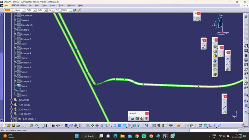
Closed Body Formed
by using sweep command with reference to surface and tooling axis direction we created the c surface and then by joining the class A surface with sweep we created and then trimming it with b surface we got closed body
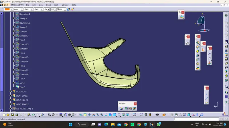
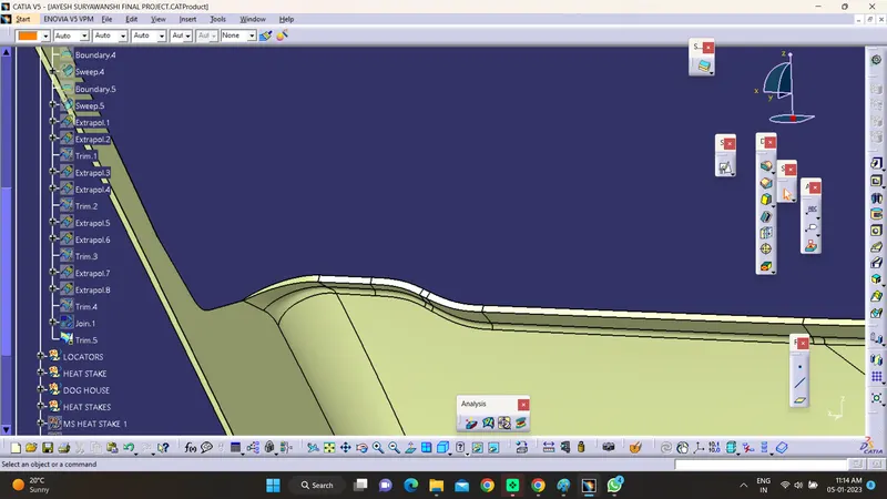
like this only we have created solid bodies for all components
BOTTLE HOLDER
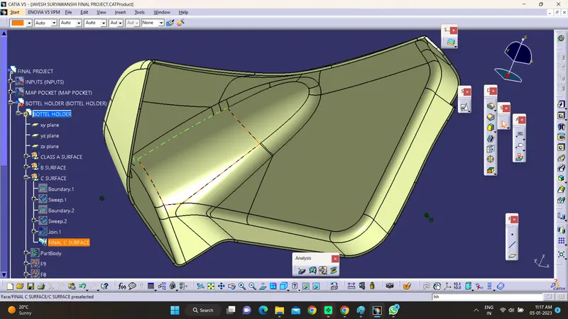
MAP POCKET
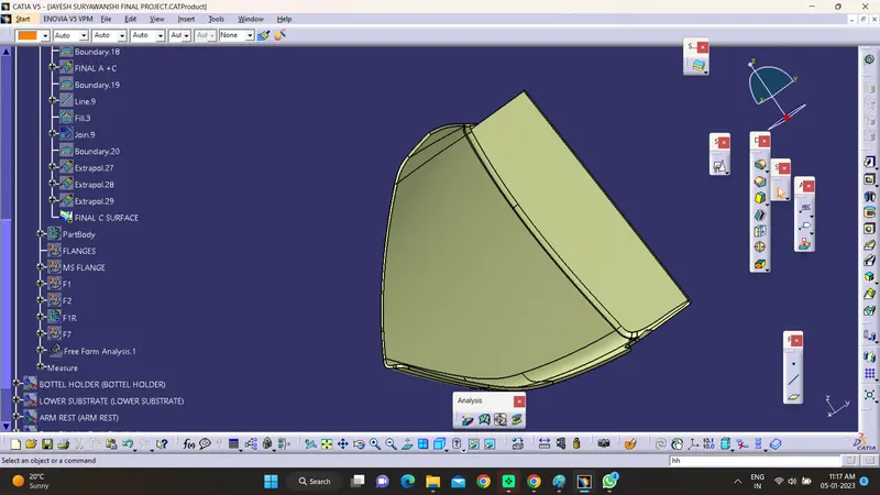
ARM REST
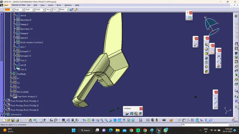
DESIGNING B SIDE FEATURES:
DOG HOUSE: Primary function of the dog house is to avoid sink marks. But it also helps in other things like if the mating part is to be at a greater distance then we cannot make the height of the screw boss of that greater height, thus we make dog house and mount screw boss on it. Hence it helps in solving the probelm of screw boss and also it helps to have perpendicular screw boss.
the exact position and guidelines are not provided for the so minimum design consideration for Dog House we have followed in our project
i.e. min 50 mm clearence in the opening of dog house so that slider will come and do work here.
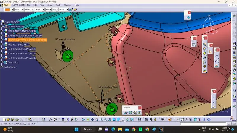
There are certain guidelines to be followed while creating the dog house which followed in the project properly.
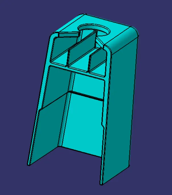
Push clips are mounted on this dog house. But as the push clip are manufactured else where and is not in our zone of concern so we have ignored the rules while making the push clips.
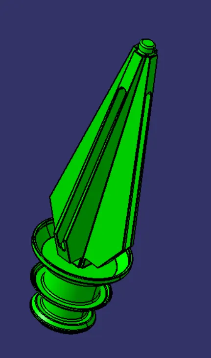
Draft Analysis on Dog House:
They have seperate lifter axis inorder clear the draft analysis inside portoins.
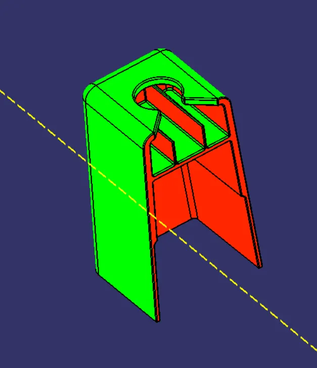
Outer faces are clearing with 0.5deg in main tooling axis.
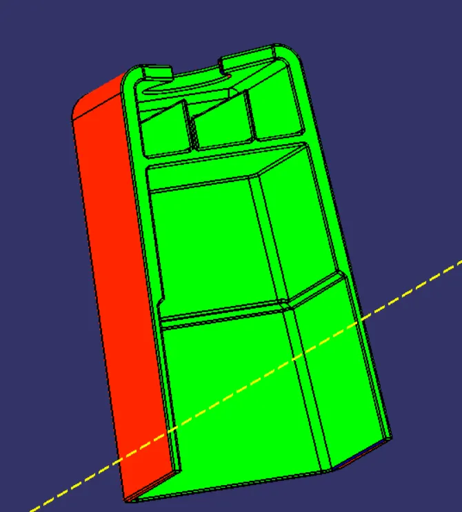
Inside faces are clearing with 0.5 deg in Side Core axis.
Heat Stakes: It is the process used to join two or more parts by deformation of the plastic by applied heat and pressure, for a certain time. The applied heat melts the extruded heat stakes on the primary component and it settles on the secondary component. After cooling both the components are firmly joined.
NOW THE POSITIONING OF THE HEAT STAKE =
this plays very imp role in B side feature that where to position the heat stake we have positioned the heat stake in such a way that 50 mm clearence is there means in row at distance of 50 mm we kept between two heat stakes. we have positioned all heat stakes on LOWER SUBSTRATE
And the height of heat stake by industry rules id 25 mm to 50 mm so we keep it at 27mm of height
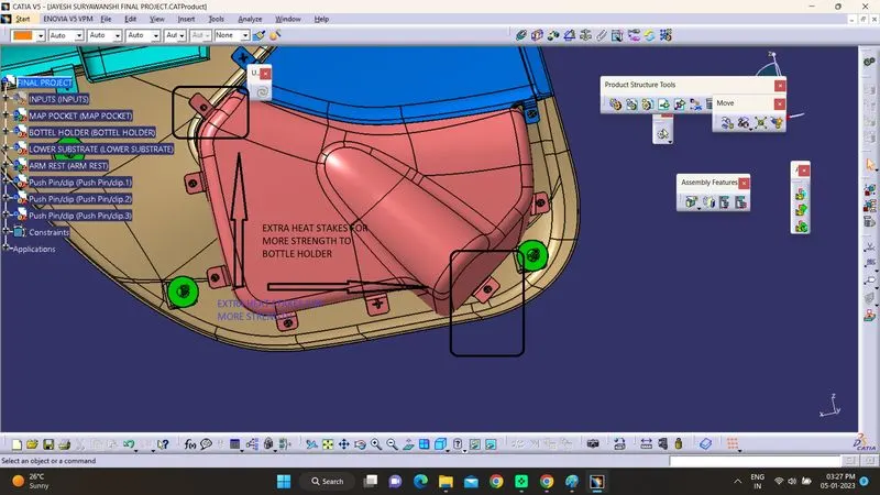
(1) We have created 3 Heat Stakes for joining the ARM REST TO LOWER SUBSTRATE and 1 Locator
(2) In MAP POCKET and LOWER SUBSTRATE joining we created 3 Heat Stake and 1 Locator
(3) In BOTTLE HOLDER and LOWER SUBSTRATE joining we created 6 Heat Stake and 1 Locator
we have given extra heat stakes to bottle holdere because the bottle will be kept in bottle holder so it will need more strength so we have give 6 heat stakes to join the bottrle hoilder and loweer substrate.
Draft Analysis:
MINIMUM DRAFT = 0.5 DEG
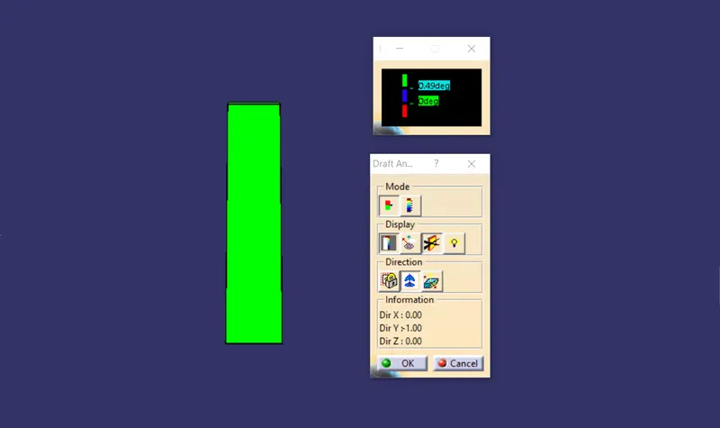
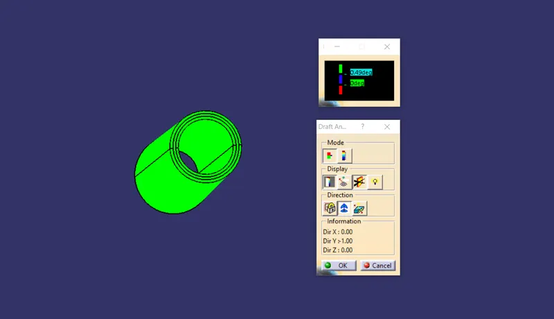
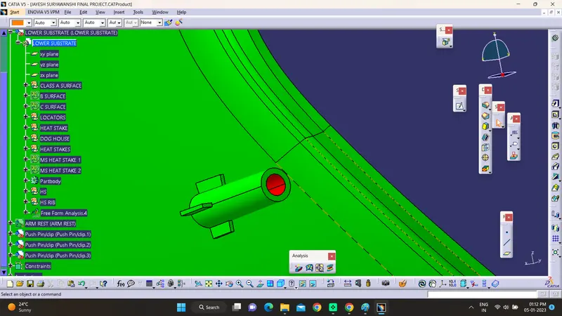
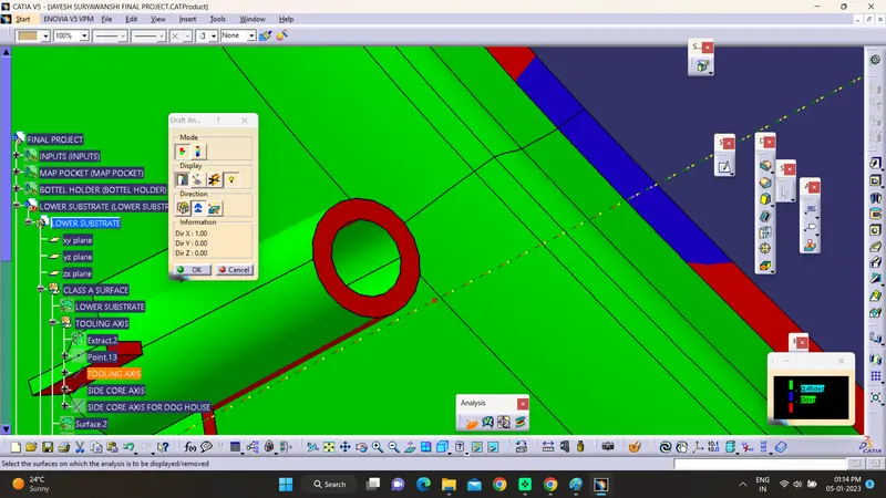
first one is with main tooling axis and second one is with side core axis with both the B side Feature are clearing draft analysis
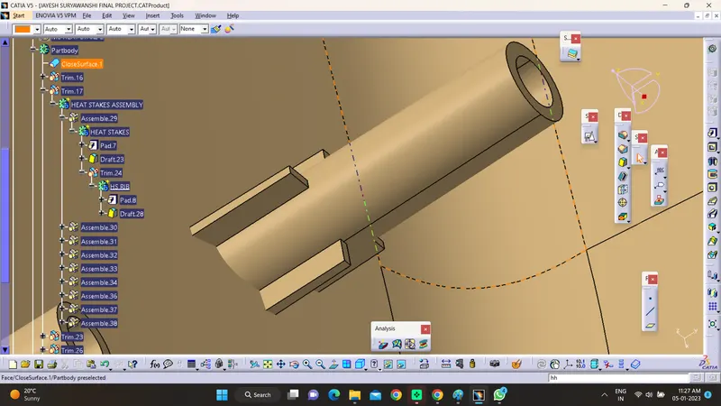
Ribs: Ribs are the features which are used to provide strength and stiffness to the component. Rather than increasing the thickness of the whole component providing ribs reduces cost and also serves as guides for assembly of two components wherever necessary.
Design Rules For Ribs:
- Thickness of the Rib = 0.4 * thickness of the component.
- Rib Root Thickness = + or - 30% of thickness of the component.
- Rib Fillet Radius = 0.25 mm
- Draft = 0.5 deg
- Rib depth < or = 5 * thickness of the component.
- Height / width ratio = 3:1 or 2:1 ( Preferred)
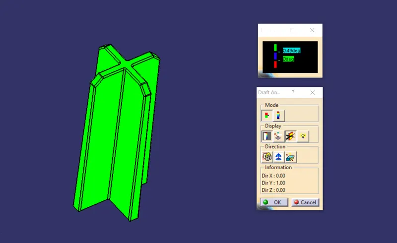
Locators: Locators are the features on the plastic component which enables us to arrest the degrees of freedom of the part and helps in fixation of the component.
The two types of locators used here are:
- 2-Way Locator
- 4-Way Locator
Design Rules For Locators:
- Thickness of the Locator = 0.4*thickness of the component.
- Fillet Radius = 0.25mm
- Draft = 0.5 deg
NOTE: The height of all the locators should be equal.
and the height provided we is 30 mm more than HEAT STAKE because firstly locator will fix and after that heat stake so we keep height of locator is greater than that of heat stake
Draft Analysis:
4-Way Locator
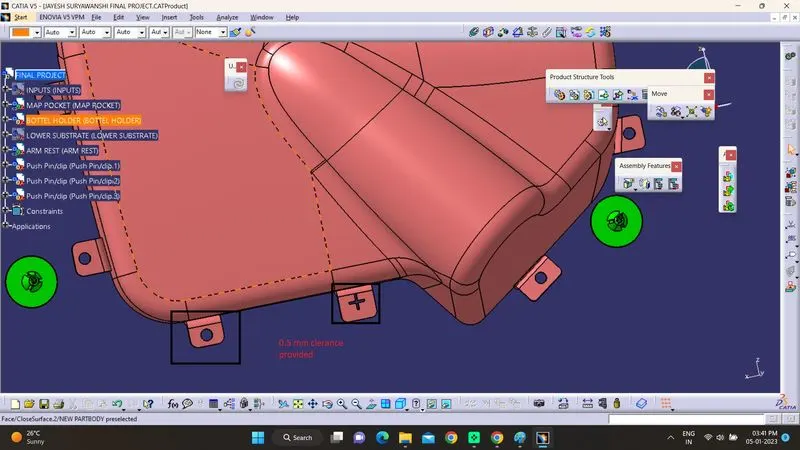
Flanges: Flange is a feature designed for attachment of two component purpose. It has holes in it which helps us mounting one component on the other and carry out the heat staking process.
also we have provided 0.5 mm clerance to theheat stake and locator (holes in flanges)
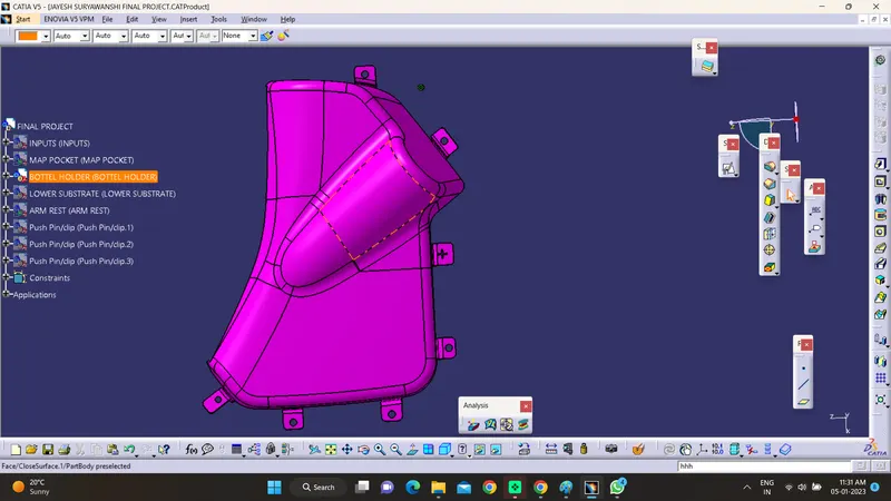
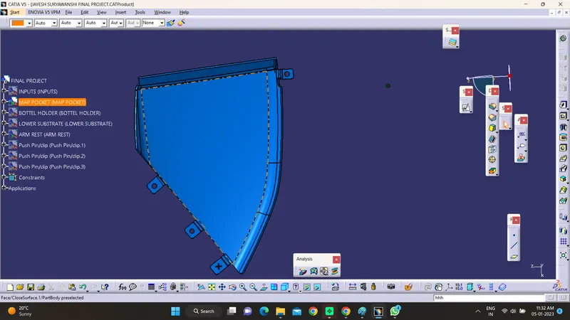
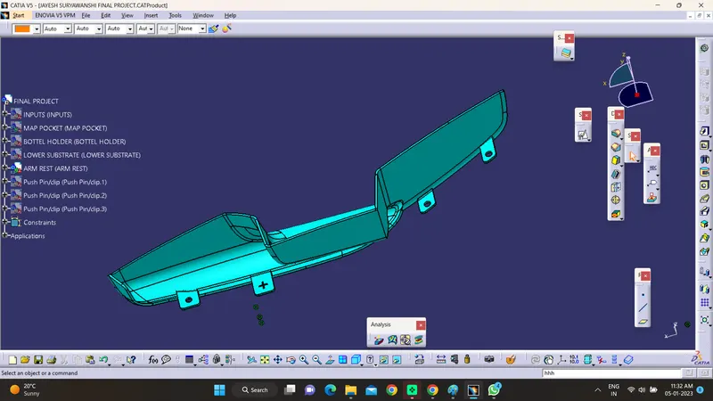
Draft analysis final Component
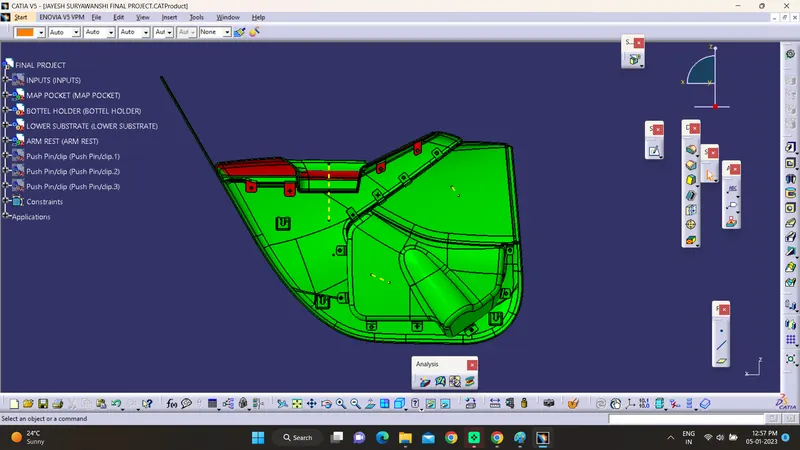
here we can see that some patches of bottle holder and arm rest are not clearing draft analysis with main tooling axis beacuse of gives class A surface is not proper and that is the reason that some patches are not clearing tooling axis direction
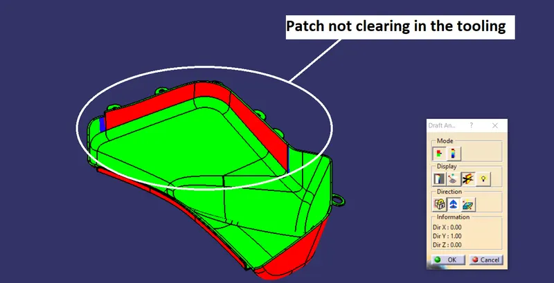
and the flanges of the arm rest are clearing with the side core axis
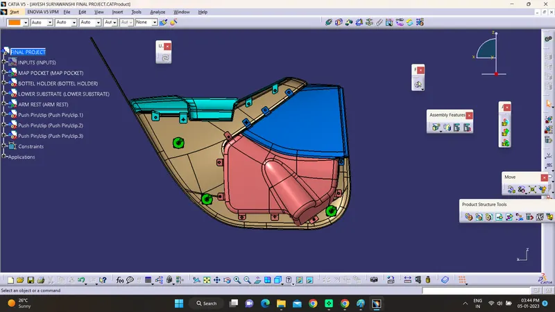
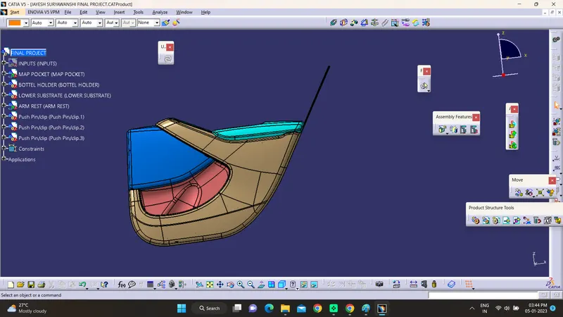
SO THE FINAL COMPONENT OF OUR PROJECTB IS AS FOILLOWS=
RESULTS:
- Class A, B and C surface was created as per the automotive standards using CATIA V5 Software.
- Draft Analysis was performed for the built model and it could be seen the the draft was under permissible limit for the manufacturing of the component.
- B side features were created for the component as per the design Rules.
- We have successfully designed the lower trim for the door panel from a given Class-A Surface in Catia-V5.