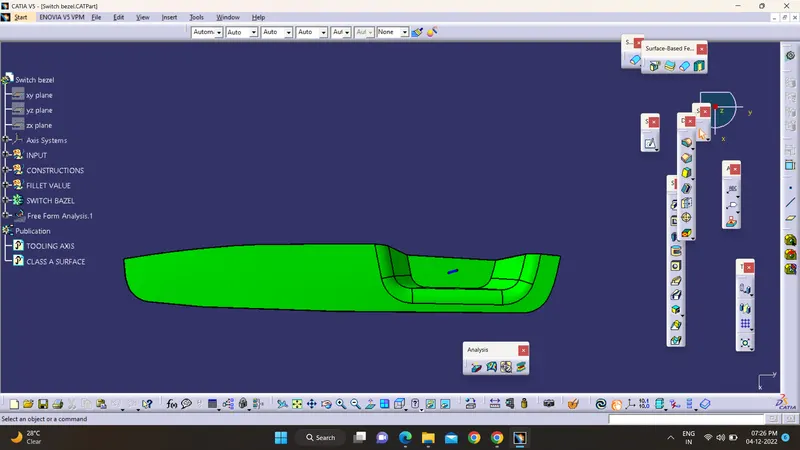
Week 8 - Challenge 2 - Switch Bezel Design
Tooling Axis:-
To Import Class A surface in the drawing.
Using intersection method and bisecting line method created Tooling Axis.
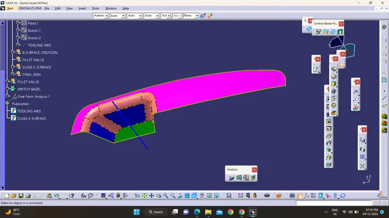
Explaining the Draft Analysis and the Tooling Axis creation.
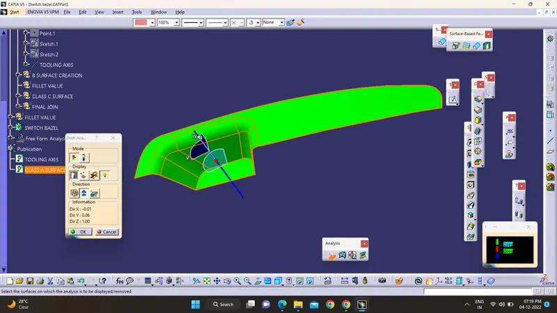
after that we need to perform Draft Analysis on CLOSED PART BODY and for that we need to attach Axis System to TOOLING AXIS after that we need to see the our surface having what Draft angle actually general draft angle ranges from 0.5 degree to 3 degree then we can see two colors on after draft anaysis it is of GREEN and Bottom of BLUE which represents that our Draft analysis is right and if we can see some RED patches on itr then our draft angle needs to be update or change then we need to check suitable draft value for it and need to Rectify that
Draft Analysis:-
The draft analysis will help you quickly gather the draft angle on multiple surfaces manual measurements.The first step is to change your shading style to “Shading with Material”.The next step is to click on the draft analysis icon in the Analysis toolbar.Draft analysis initially assumes a Z axis direction.This can be done with the dragging of the compass with respect to the Tool axis direction.Now that the draft direction is fixed, you can gather the draft angles along different surfaces using the “on the fly” mode. Simply activate the icon within the draft analysis dialogue box and hover your mouse over the surface.using “invert draft direction method” check the color variation in the part and analyze the draft angles in the part.now ok with this position and lock the current orientation.
B Surface:-
Based on Class-A surface, now I'm creating B-surface.now i converted this surface into three different parts like Rib-1, Rib-2 & Base Surface.extracting and untrim this surface after that offsetting 2.5mm.after that create the edge filet for all the edges.

C Surface:-
For creating C-Surface, now take the boundary line for class A surface.To click sweep command based on selected boundary line and tooling axis with the outside angle of 3degree.same method follow for that two holes also.finally join these three surfaces.
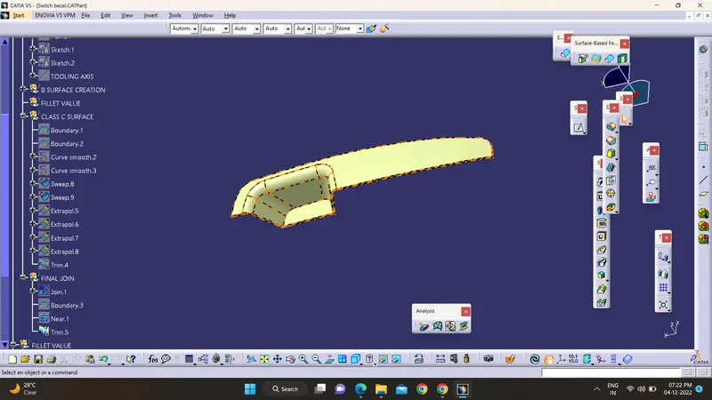
- Screenshots of the Draft analysis report for both the given Class-A surface and the final plastic component
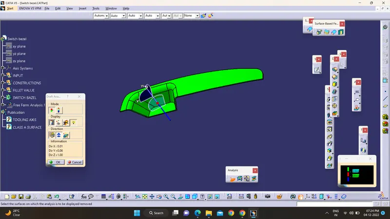
ISO VIEW
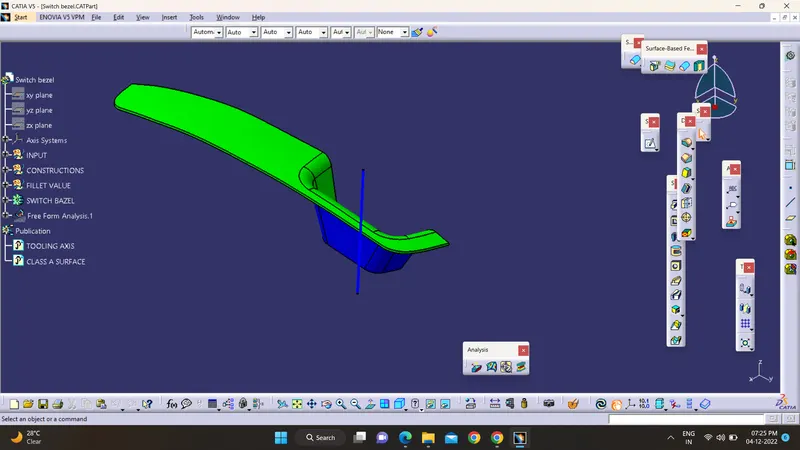
FRONT VIEW
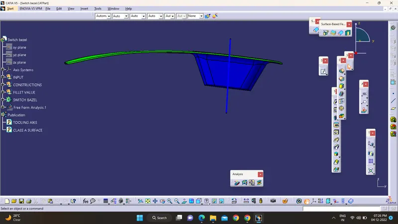
SIDE VIEW
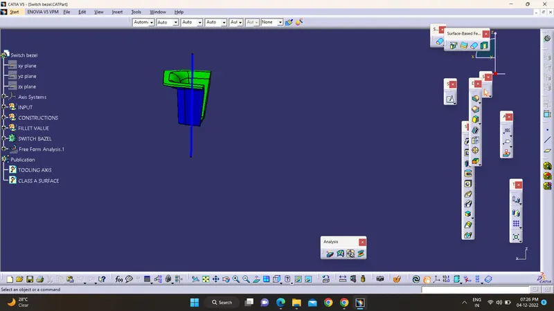
TOP VIEW