Week 11 - Final project
AIM
To create a door interior part from the inputs of class A surface with the master section by following the design rules that has been provided by the skill-lync and also followed in tier 1 and OEM industries in catia v5
OBJECTIVES
- Create a sketch by using positioned sketch
- All the sketches should be iso-constrained
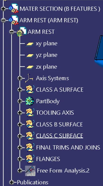
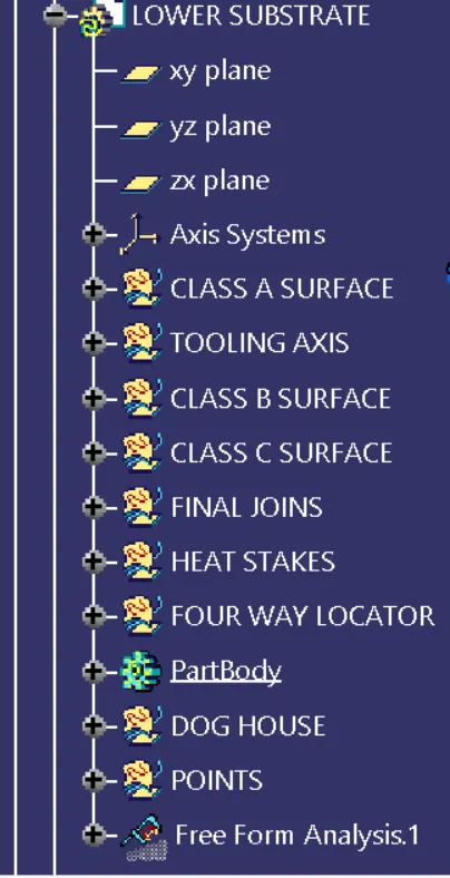
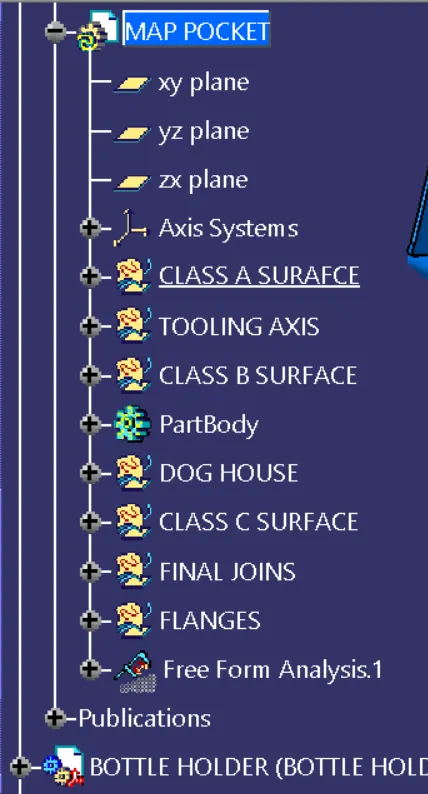
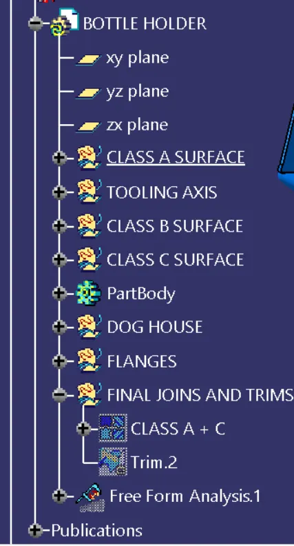
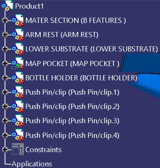
- Ensured Proper tree structure
- Geometrical sets should having a proper name based on the sketches present inside of it
- Create thickened part using master section for reference
- Create the mounting features as per design guidelines with the master sections
- Creation of Draft analysis & Tooling analysis
INPUT OF CLASS A SURFACE
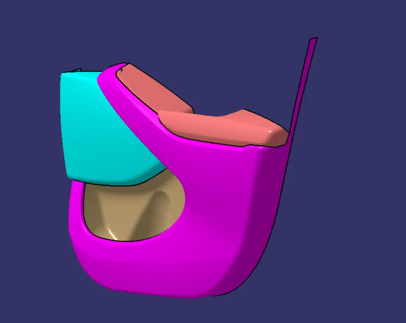
As we can see in the above image the Class A input given to us is in four different parts, So the Class B surface and Class C surface should be created in separate catpart. And we'll have to perform the draft analysis and tooling axis for them separately, and finally all the four parts assembled together in one catproduct file.
CREATION OF TOOLING AXIS - ARM REST
PROCEDURE
- Check the Class A surface with the boundary command that it is connected or not, If it is connected then the Class A surface will only have the outer boundaries, and if it is not there will be boundaries in the middle of the component also.
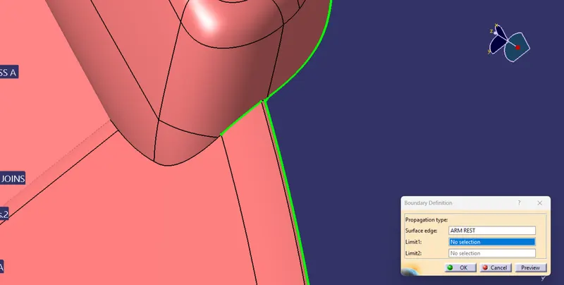
- So after checking the component with the boundary command we found a opening in the class A surface, Generally we don't do any changes in the Class A surface, in the OEM's or tier 1, if there's a problem with the Class A surface we report that problem to the Class A designer and then he'll correct those mistake's and then he'll give us a new class A surface to work on, but for now we can resolve the problem with the class A and move on to the creation of Class B surface
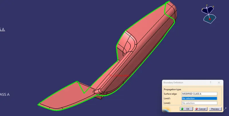
Now we recreated the class A surface according to ourselves.
- Check the model visually & choose the best tooling direction which should be easy for draft.
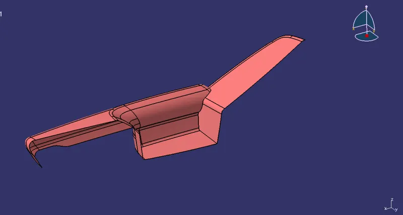
- After analyzing the above model we'll have to make the tooling axis in z direction, but our above component is a bit complicated one so it won't clear all the parts with just one tooling axis we'll have to create the tooling axis in x and y also otherwise it won't clear in draft analysis.
CREATING THE TOOLING AXIS
- Create a point on the Arm Rest and then after that insert a axis system on that point as shown below;
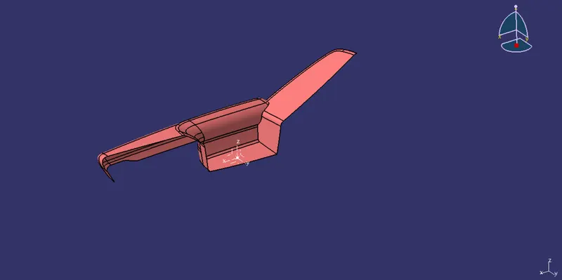
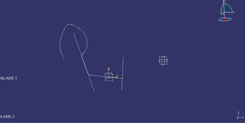
- Create a intersection on ZX plane for the given surface
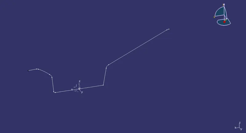
- Create a point to point line as shown below
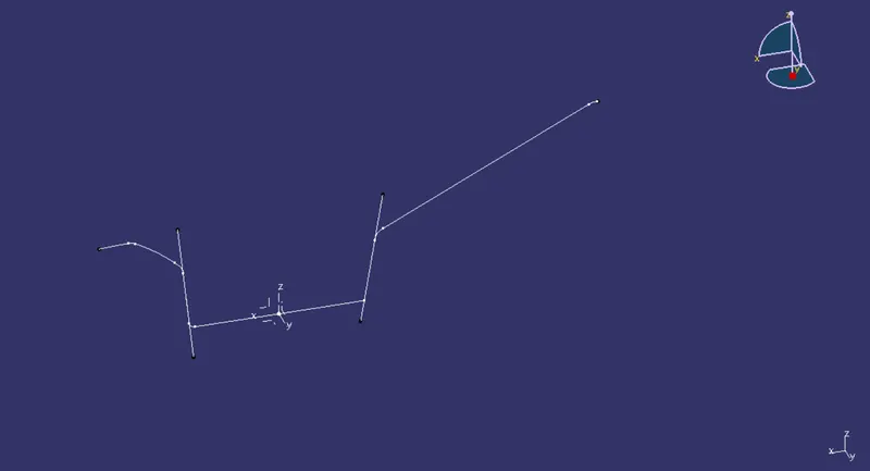
- Create bisecting line, by the the refrence of two lines, as shown in the above image and with the help of the point in the centre of it with these three as the reference we can easily create a bisecting line and after that name it as dummy tooling axis 1.
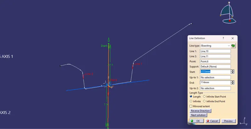
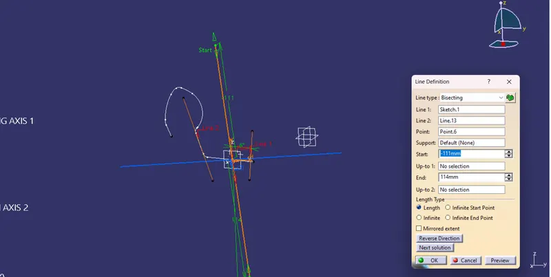
- After that we'll create a intersection on the zy plane for the dummy tooling axis 2.
- Now again with the help of two lines and a point, taking them as a refrence and then againg creating a second bisecting line with that, and name that line as dummy tooling axis 2.
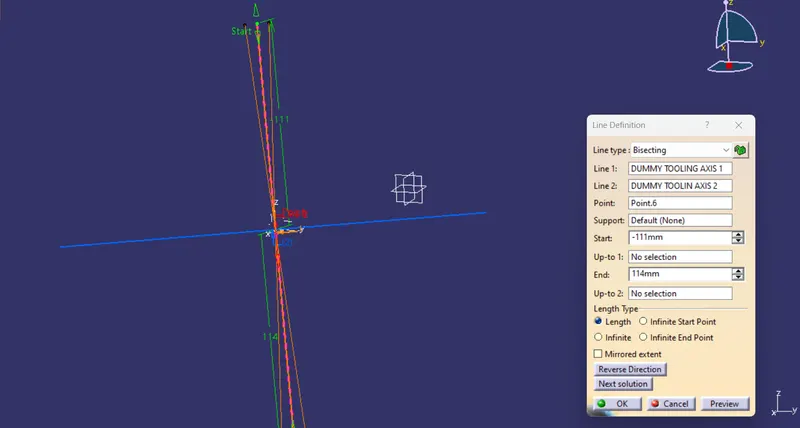
- Now with the help of two dummy tooling axis we can easily create the main tooling axis for our arm rest easily by yusing the bisecting method in it and the two dummy tooling axis as refrence and a point to to create the bisecting line.
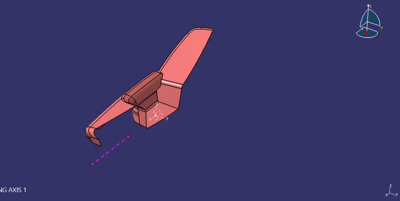
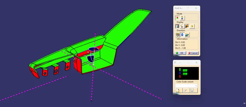
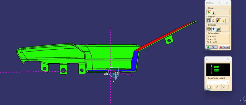
- In the Arm rest one tooling axis isn't enoung to clear in the draft analysis so we'll have to crate two more tooling axis in other two directions also,
CREATION OF SIDE TOOLING AXIS X
- Create a point on surface and create a line using point direction, use direction as X axis.
- Drag a compass and place it on axis that we created. Adjust the compass till we get correct view. lock the orientation of the compass.
- Modifythe above line by changing the direction along compass
CREATION OF SIDE TOOLING AXIS Y
- Create a point on the surface and create a line using point direction, use direction as y axis.
- Drag a compass and place it on axis that we created. Adjust the compass till we get correct view. lock the orientation of the compass.
- Modify the above line by changing the direction along compass
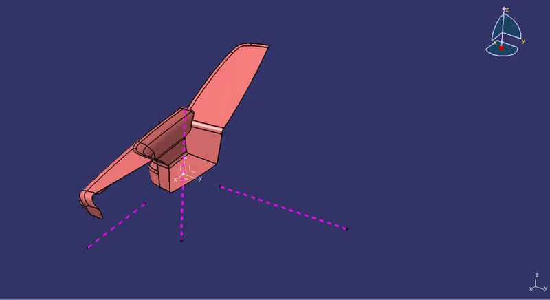
- Now with the help of these three tooling axis we can easily clear the draft analysis for the arm rest
CREATION OF TOOLING AXIS ON LOWER SUBSTRATE
PROCEDURE
- Check all the boundary whether it is connected properly or not and while checking the Class A surface with the boundary command we also need to keep in mind that the surface is properly closed and it is not creating any boundaries on the inside and if it is creating any boundaries on the inside of the surface that means the surface isn't properly closed, and if the class A surface isn't proper than we should inform the class A engineer to correct the surface properly.
- Check the model visually & choose the best tooling direction which should be easy to draft.
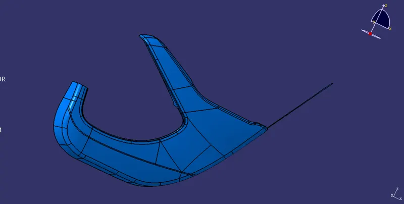
- After analyzing the above model the best tooling axis is y direction
CREATION OF TOOLING AXIS
- firstly extract a surface from class A surface and after that we'll create a point on that surface
- Create a point on centre of gravity of part by using measure inertia command and insert a axis system on the point as shown below
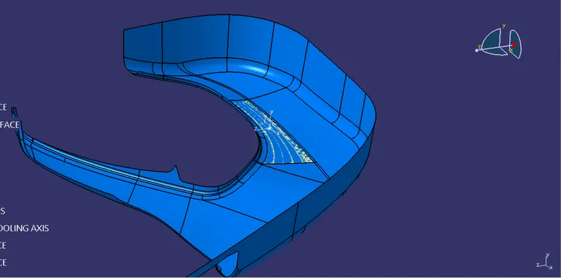
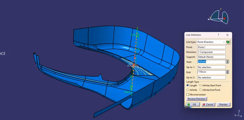
- create a point-direction line parallel to the y axis and named as Tooling Axis as shown below
CREATION OF TOOLING AXIS FOR BOTTLE HOLDER
- Firstly we need to check that the surface is a close one or not by using boundary command
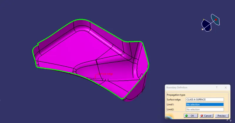
- After that extract a surface from class A and then create a point and a Axis System on that extracted system
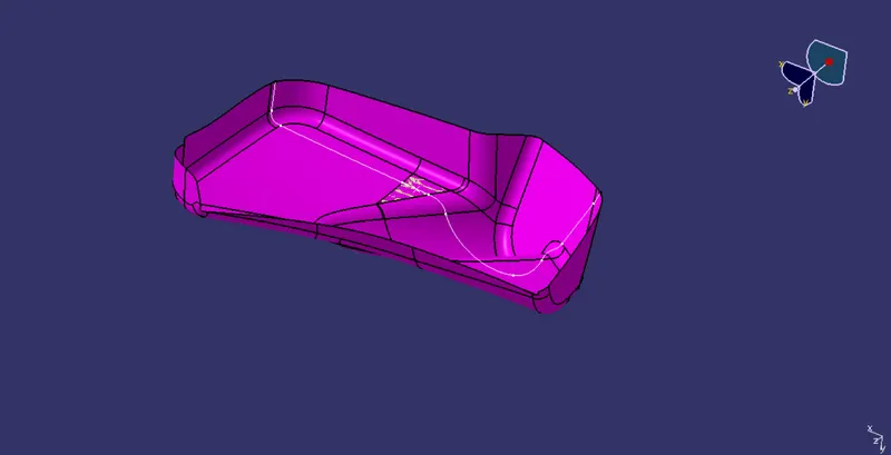
- After that we can just use point - direction for creating the tooling direction for the bottle holder
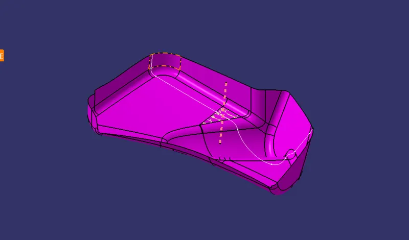
CREATION OF TOOLING AXIS - MAP POCKET
PROCEDURE
- Check all the boundary whether it is connected properly or not.
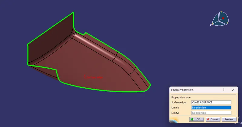
- Check the modle visually & choose the best tooling direction which should be easily draft.
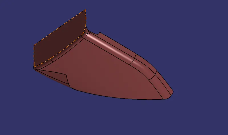
CREATION OF TOOLING AXIS
- Extract a component from the Map pocket, try to extract from the centre of the component and after that create a point on that extracted portion as shown below
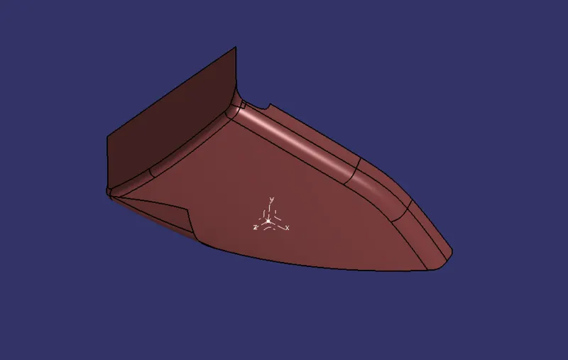
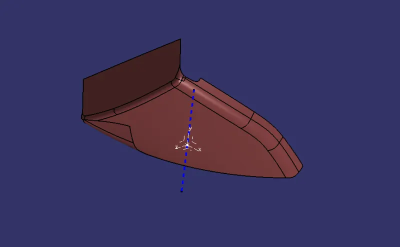
- Create a line using point - direction command and the line should be parallel to the Y axis and named as TOOLING AXIS as shown in the below image
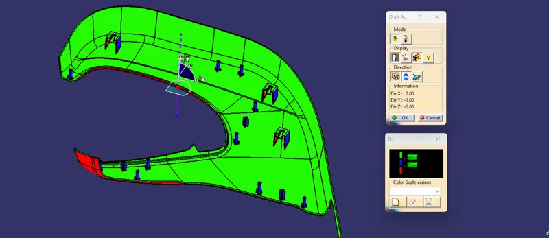
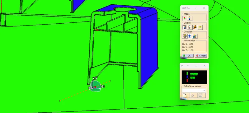
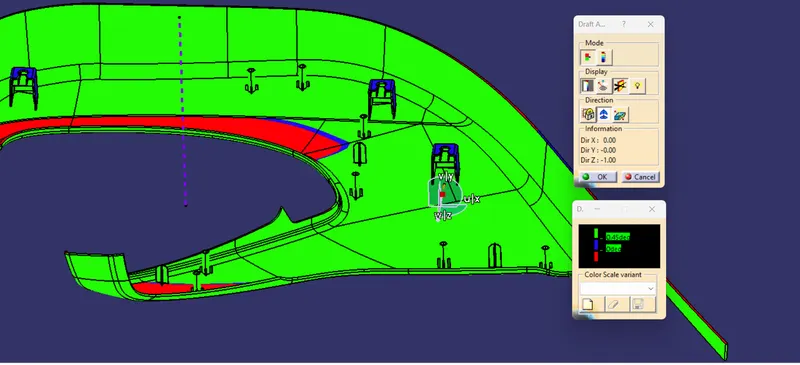
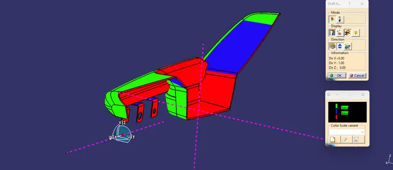
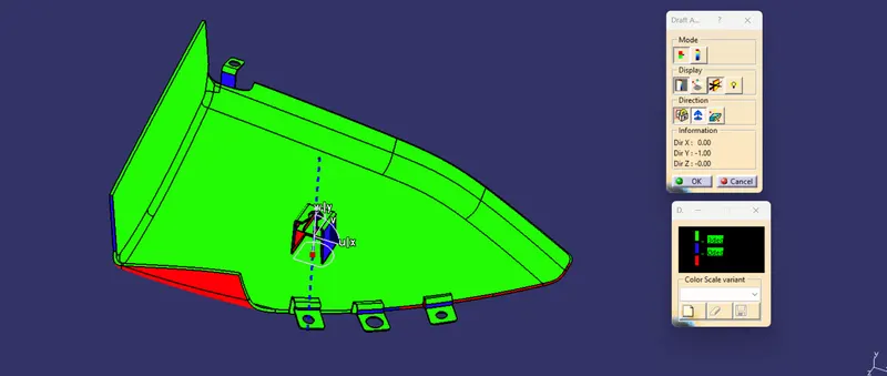
PERFORMING DRAFT ANALYSIS ON MODEL
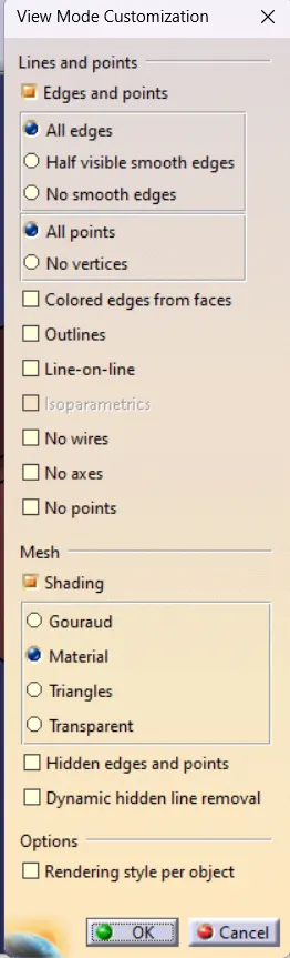
- To perform draft analysis on the model firstly we should open customize view parameters and then a dialogue box will be opened ( View mode customization ) and then in that we need to choose the mode as material
- After that insert a feature draft analysis by following these commands
insert>analysis>feature draft analysis
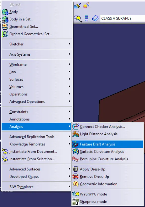
- Then our feature draft analysis dialog box will look something like in the below image
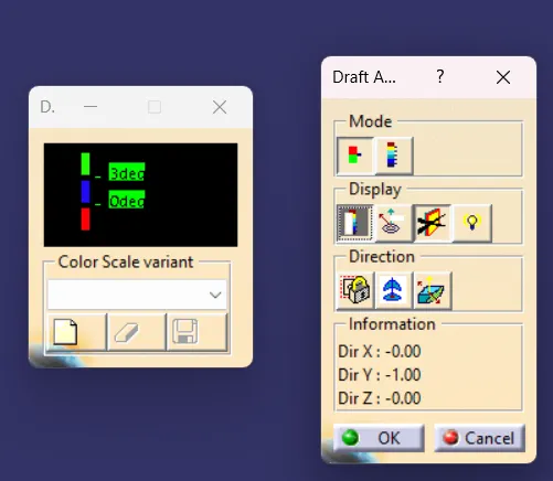
- Align the compass on tooling axis that we created
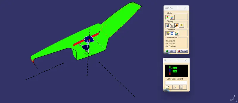
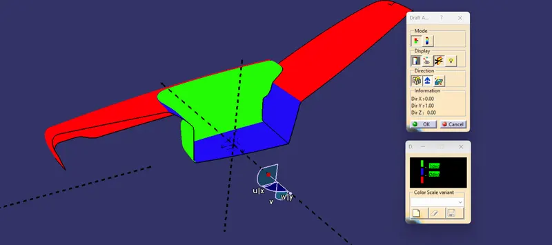
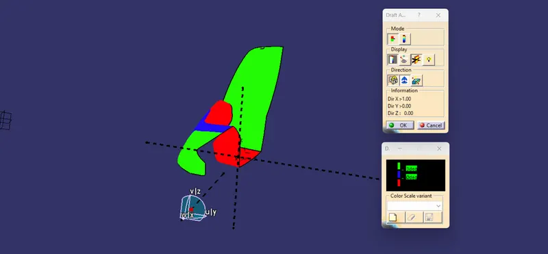
- Open the color scale and enter the value as 3 & 0 deg.
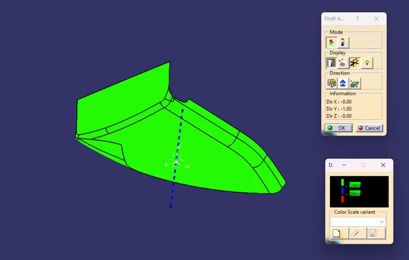
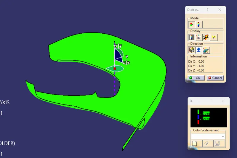
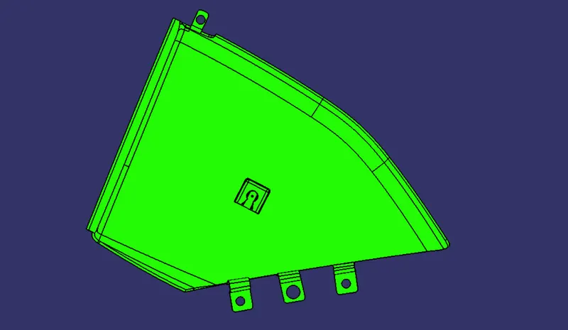
- If the whole body is green that means all the faces is greater than the provided angle
DRAFT ANALYSIS REPORT OF CLASS A - MAP POCKET
DRAFT ANALYSIS REPORT OF CLASS A - LOWER SUBSTRATE
DRAFT ANALYSIS REPORT OF CLASS A - BOTTLE HOLDER
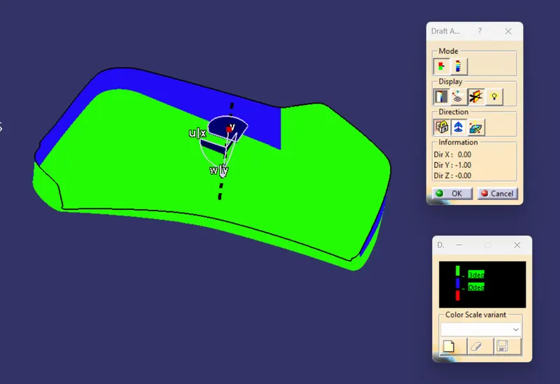
DRAFT ANALYSIS REPORT OF CLASS A - ARM REST
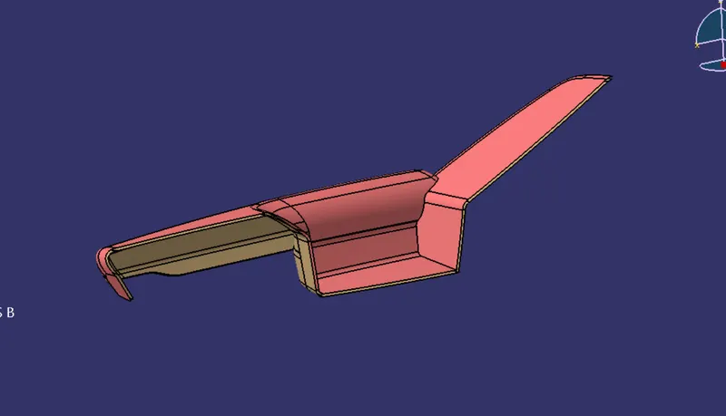
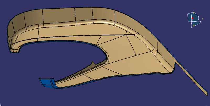
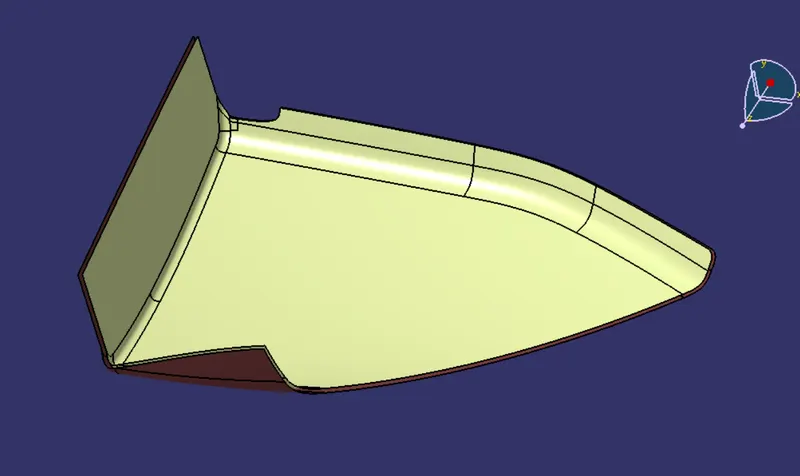
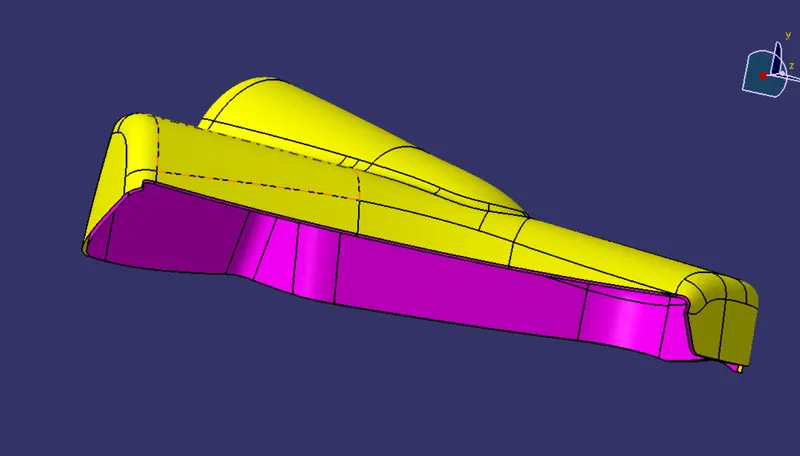
CREATION OF CLASS B SURFACE
- Insert a new geometrical set
- Measure the thickness of the components in master section, The value is 2.5mm
- Offset the Class A surface to 2.5mm
- Check all the sub elements are formed, if not try to fix it locally
ARM REST CLASS B
LOWER SUBSTRATE CLASS B
MAP POCKET CLASS B
BOTTLE HOLDER CLASS B
CREATION OF CLASS C SURFACE
- Analyze the class A, and try to to find where the sweep is easier to create towards tooling direction
- In most of the surfaces the sweep won't happen in one go, for that we'll have to create seprate boundaries for the sweep and then perform it
- Create the boundary using limitation points where the sweep is possible.
CLASS C SURFACE OF ARM REST
- Firstly create the outer boundary of the Class A surface, and then try to sweep in one go
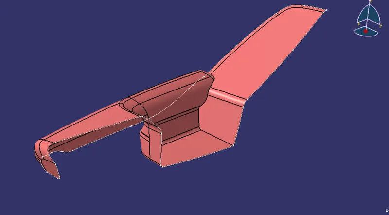
- For the Arm rest the sweep won't happen in one go, so we'll have to create seprate boundaries and then try to sweep it, and for some areas the sweep won't happen at all for that we can use multiple options; like extrapolating class C surface and then triming it with each other or using multi-section command to create the sweep with the help of other sweeps
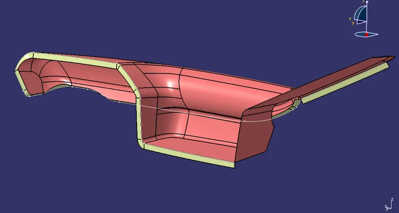
- We are creating seprate boundaries and then sweeping it, as you can see in the above image
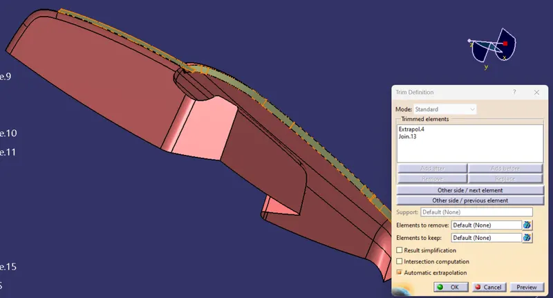
- Then we'll trim the extra sweep that is happening, we can see in the above image for the reference
- And for the remaining surface we'll use multi- section surface command to create the missing patches,
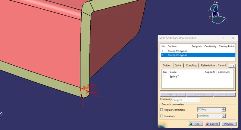
- At last we'll use the join command for joining all the sweeps together
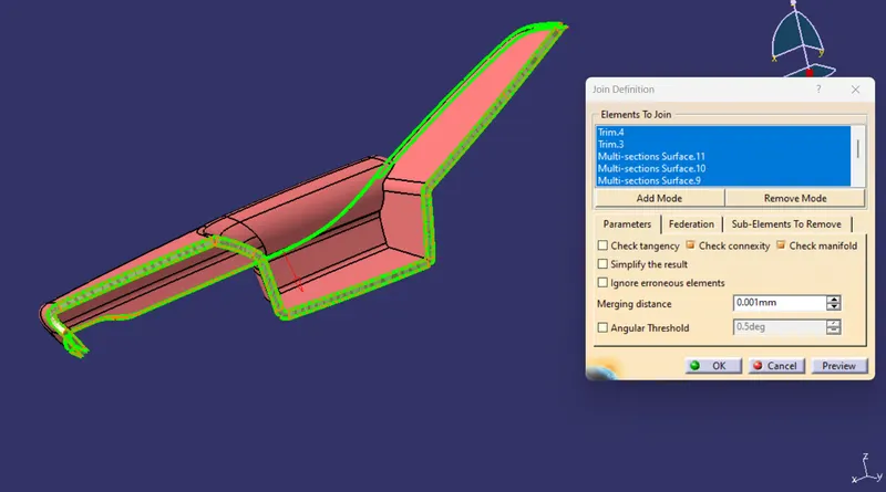
- By using all these commands and following all these features we'll have our Class C surface
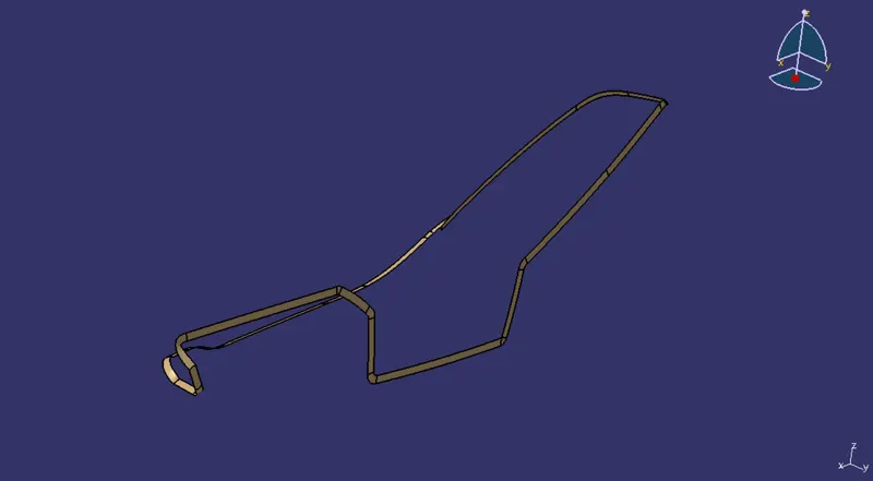
LOWER SUBSTRATE CLASS C SURFACE
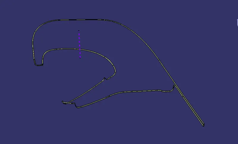
- For the Lower substrate; firstly we'll extract the outer boundary of the class A surface
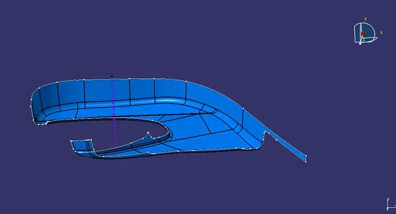
- In this component as we can see the sweep is happening, in one go and there is no missing patches, so we don't have to use multi-section command or trim command to create the C surface
- And we'll be giving the angle as 87 degree and for creating C surface the subtype we'll be using is with reference surface, and giving the Guide curve as the boundary we created on Class A surface and the Reference surface as the the Class A itself; as you can see in the below image
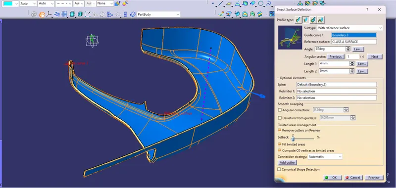
- And our Class C surface will be created easily
MAP POCKET CLASS C SURFACE
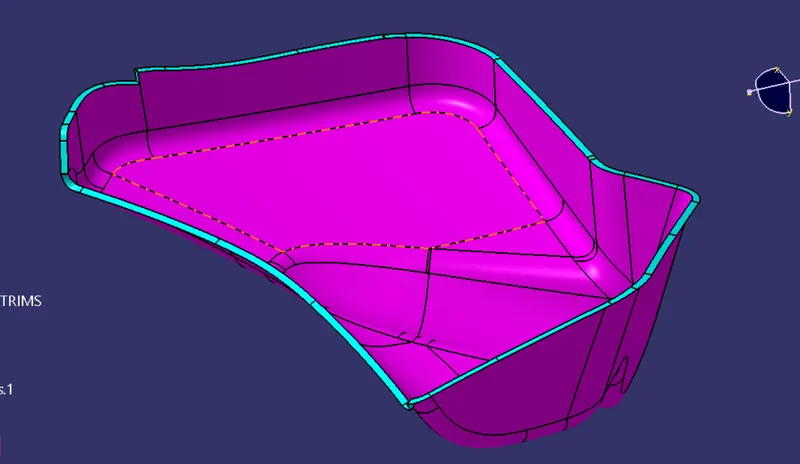
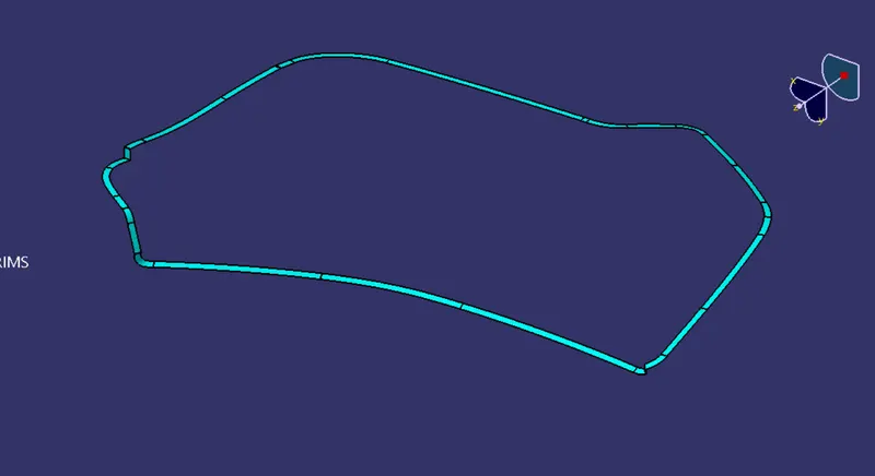
- We'll create the boundary on Class A surface, for reference as the sweep
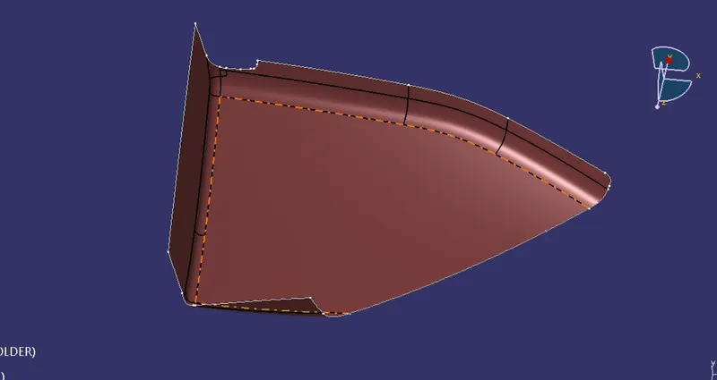
- And the sweep will happen in one go for all the Class A surafce
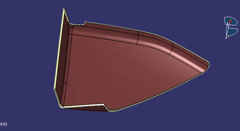
- As we can see there is no patches missing in our sweep so, we can join it with class A surface and then trim it with class B surface for a closed surface
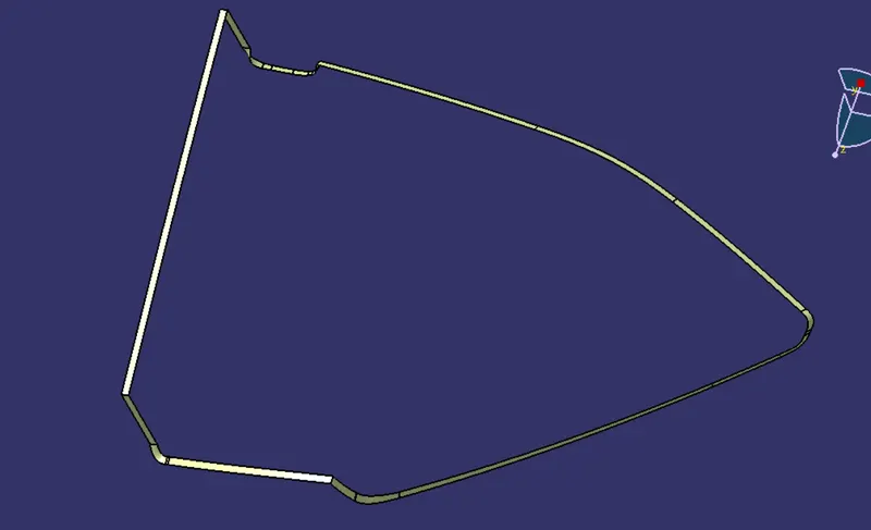
BOTTLE HOLDER CLASS C SURFACE
CREATION OF B SIDE ATTACHMENT FEATURES
Dog House
- Extract a surface from the closed body and then create a point on that extracted surface then create a sketch for the the dog house walls
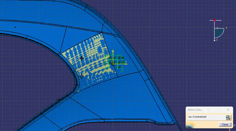
- Well we can just extract that line and then we can give the draft angle to the dog house or we can just use the sweep command to extract the dog house that way we can give the draft that is needed in the tooling direction
- Insert a axis sysytem, use positioned sketch and draw a dog house sketch
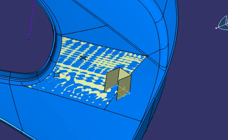
- For the top wall we'll use the extrude command to create the top wall and extruding the top surface in Z axis, after that we'll join all the dog house surfaces
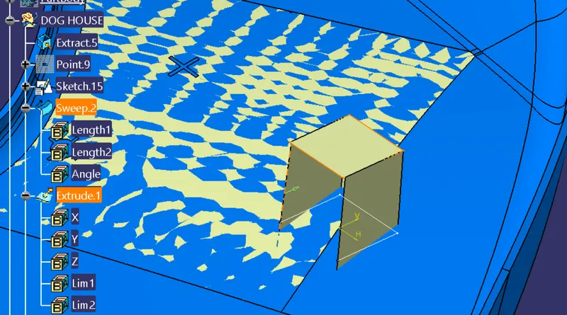
- Add thickness to the above sketch of 2.5mm by using thicken surface
Dog House Creation Rule
Height of B = 6mm
Thickness = 2.5mm
C = 0.4 * t
- Now let's consider "C" is where the doghouse contacts the backside of the surface, so we'll extract the sweep and offset to B=6mm and C=.8mm on all direction like the below
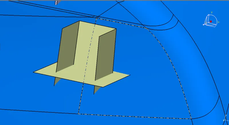
- Trim the portion to get the required sketch
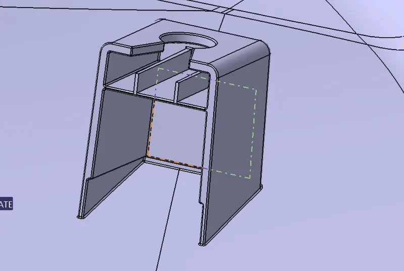
- Draft to 0.5 degree along side core tooling axis
- Add fillet to all faces
- assemble the dog house to lower substrate solid
- Translate the dog house where we need
HEAT STAKES
Heat stakes are mainly known as thermoplastic staking, it is the process of joining two dissimilar metals or non-metals together
- Extract the surface on which we are going to create heat stake
- Insert a point on that extracted portion
- And then use a positioned sketch and draw a heat stakes sketch
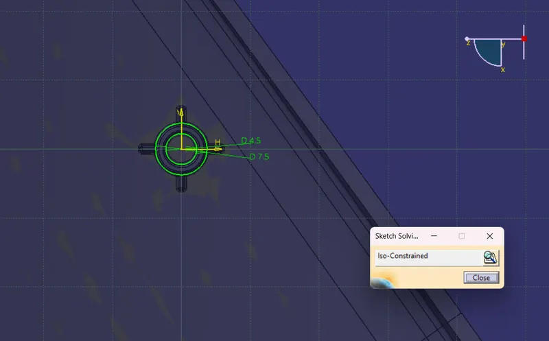
- Use pad command for the sketch to the height we require
- Draft the heat stakes to a 0.5 degree
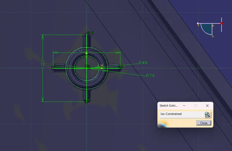
- We also need Ribs for the heat stakes cause if the height of the heat stakes increases the Ribs will provide support to it
- For the Ribs Thickness will be 1 mm
- Draft the Ribs to 0.5 degree
- Add fillet of 0.25 mm to all the faces
- And then add the heat stakes and ribs to lower substrate solid and then use bolean operation to remove extra components
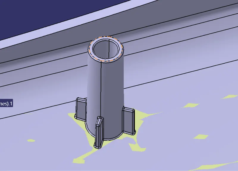
- Maintain a 50mm minimum distance between two heat stakes
- Translate the heat stakes to wherever we need
- Trim all the heat stakes with lower substrate solid
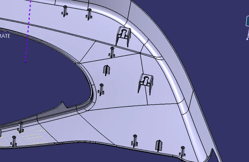
LOCATOR
- Extract the surface the surface were we are going to create locator
- Add a point on that extracted surface for the refrence of positioned sketch
- Use positioned sketch and draw a locator sketch
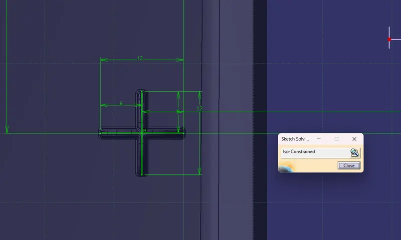
- Use pad command for the sketch till the required height
- Draft the locator for minimum of 0.5 degree
- Add Chamfer of 3mm on every edges and add 3 mm fillet to it
- Add 0.25 mm fillet to all faces
- Assemble the locator to lower substrate
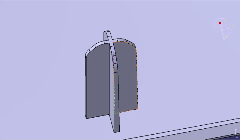
- Maintain a 50 mm minimum distance between the two locators
- Translate the locator to where we need
- Trim all the locators with the lower substrate solid
- Maintain a height more than heat stakes
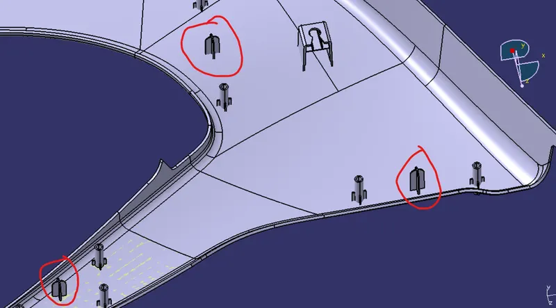
- Circle components are four way locators
FLANGE
Create a flange for attachment of heat stakes and 4 way locators at lower substrate
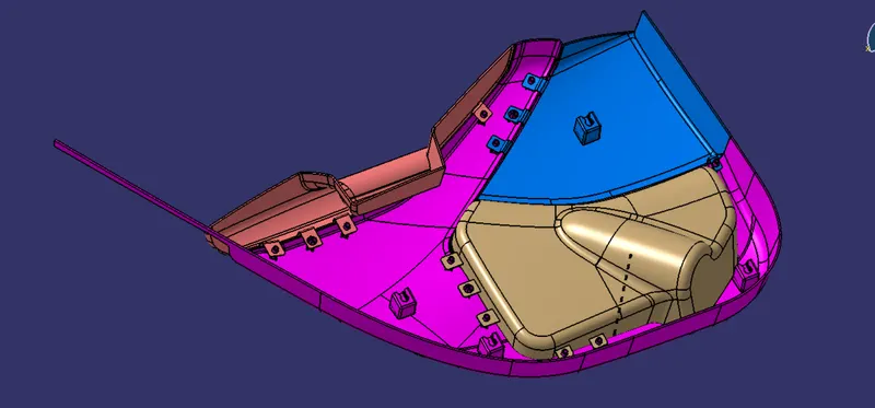
- Add fillet to the flanges also
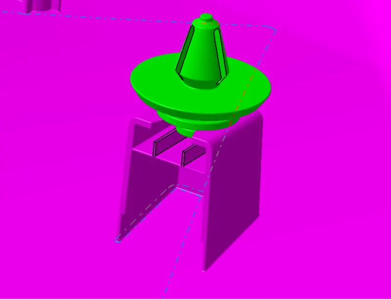
PUSHPIN
- We don't have to create the push pins on this one, it is already provided to us we can just use Insert existing components in the assembly work bench
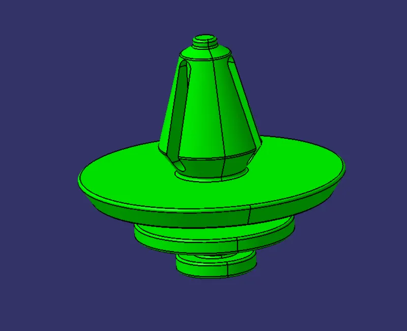
- Then use the axis to axis constraint option to align the push pin to dog house
- After that we will use offset constraint option to join these two together that way we can easily move the pushpin
- And after doing all the constraints The push pin will only rotate on the place its siting
DRAFT ANALYSIS REPORT OF LOWER SUBSTRATE
DRAFT ANALYSIS REPORT OF BOTTLE HOLDER
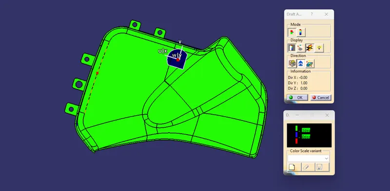
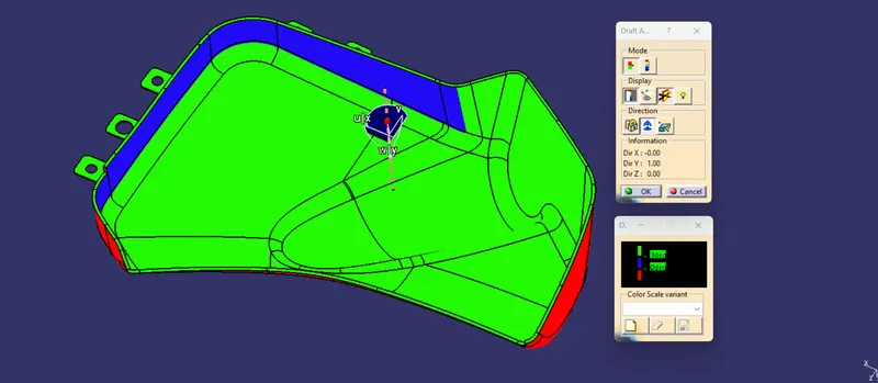
DRAFT ANALYSIS REPORT OF ARM REST
DRAFT ANALYSIS REPORT OF MAP POCKET
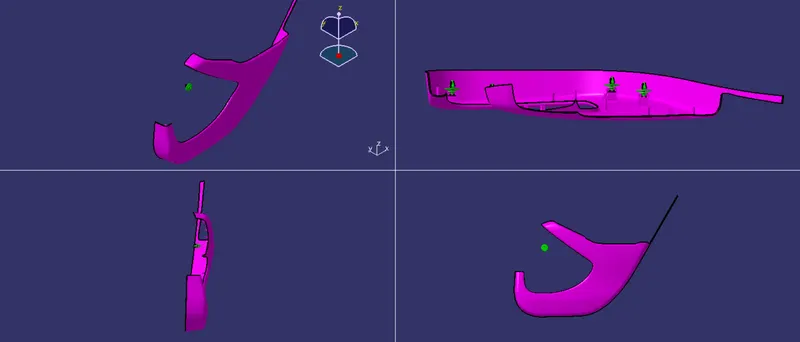
MODELS IN VARIOUS ORIENTATIONS
LOWER SUBSTRATE
ARM REST
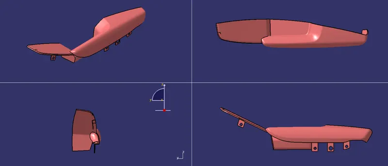
BOTTLE HOLDER
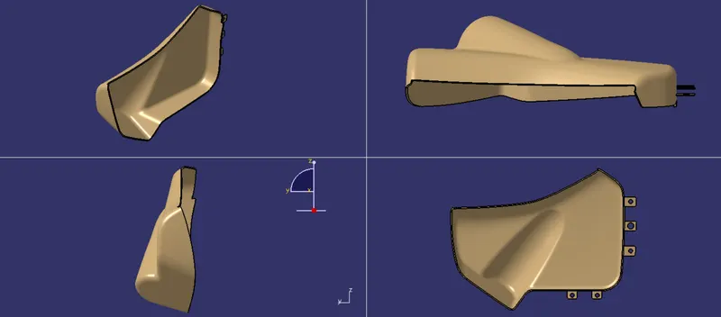
MAP POCKET
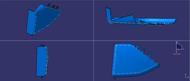
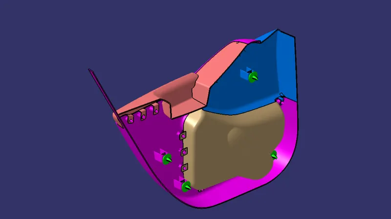
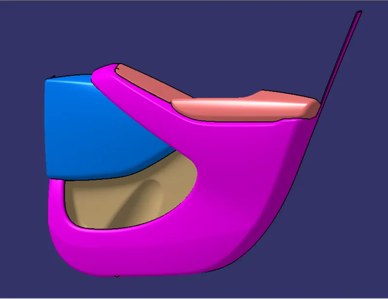
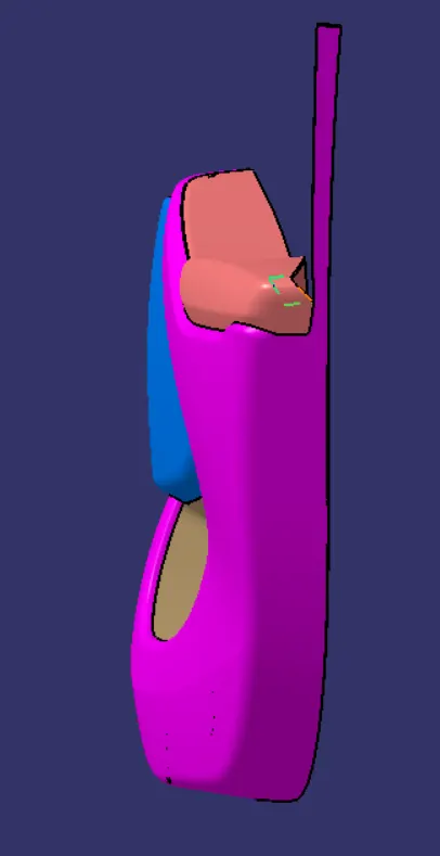
DOOR INTERIOR
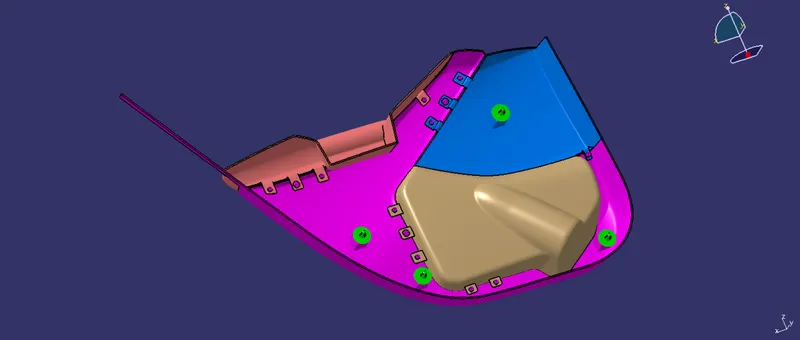
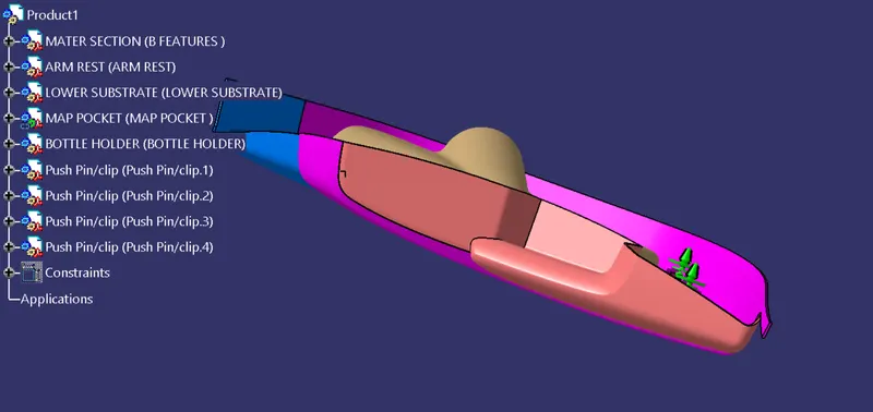
TREE STRUCTURE
CONCLUSION
Thus, the door interior part hasbeen created with the help from the inputs of class A surface along withthe master section that has been provided and by following the design rules in tier 1 and OEM industries in catia v5
We could also have created outer flange in this door interior that would have been provided strength toh the the door
And with that if there were ribs in those portions then it could have been acted as the support to the doors.