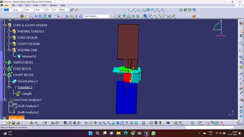
Week 8 - Challenge 6 - Core & Cavity Design
CORE AND CAVITY
AIM:
- To create the core and cavity blocks for the switch bezel component.
Description:
Creating Tooling Axis :-
The tooling direction is basically the direction the molds separates or in which direction it opens. So the mold is basically built in two seprate pieces, the first one is core and the second is cavity side. The core pulls apart from the cavity and that's the dye line or tooling direction.
- Check for gaps between the surfaces for that click on join and the preview.
- If there's a gap between the surfaces join them without a maximum tolerance of 0.003mm.
- Check for the correct position of the tooling axis
- then extract tye surface of which the tooling axis doesn't interfere with thw other elements nd new elements can be created easily.
- Create an axis system in the centre of the switch bezel.
- Then take an intersection between the yz plane and the switch bezel Class A surface.
- As we understand from the Class A surface the tooling Axis can be created by Bisecting method so for that we create two lines for the bisecting line to perform.
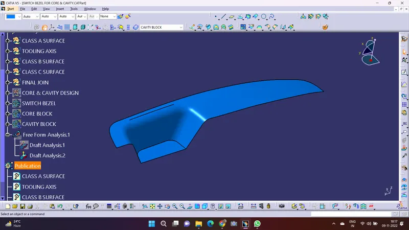
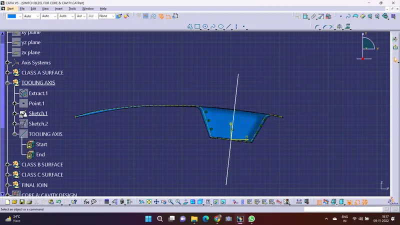
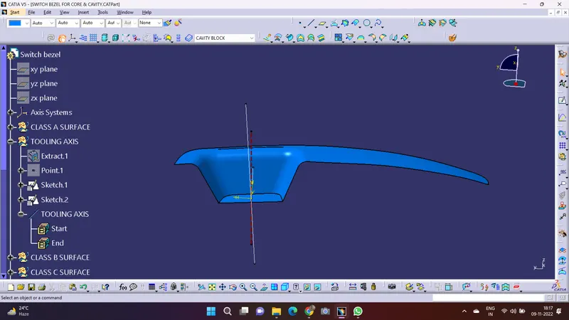
TOOLING AXIS
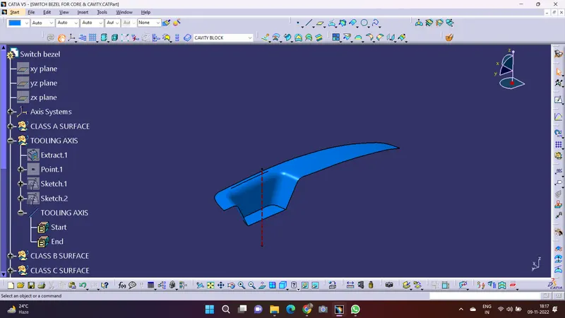
DRAFT ANALYSIS
The Draft Analysis command enables you to detect if the part you drafted will be easily removed. Draft Analysis like this is performed based on the color ranges identifying zones on the analyzed element where the deviation from the draft direction at any point, corresponds to specified values.
- Before going to the draft analysis command we need to make sure that the view parameter command is selected in materials for the draft analysis.
- Now Now for the draft analysis command we go to insert > analysis > feature draft analysis.
- Use the compass to define the draft analysis direction by placing the compass on the tooling direction.
- In the color change the draft angle should not be more than 3 degree angle.
- After that click on the class A surface in action to that the component changes to green in indicate of passing draft angle.
- use running point to check the angle on the component.
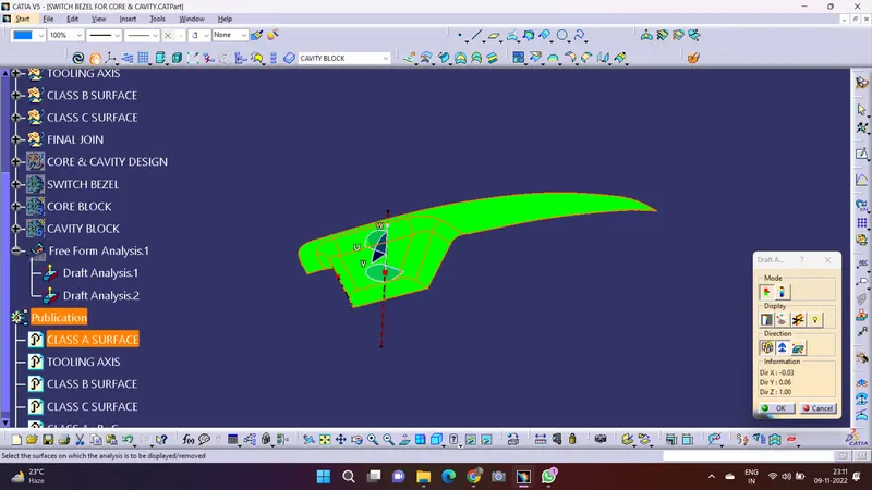

The Draft Analysis is complete now
PARTING LINE
- A Parting Line is a really important part of the injection molded products.
- In other words it can also be said that it is the line that separates the mold into two parts or the two half's of the mold meet Core & Cavity.
- It manifests itself on injection molded parts as a line that runs the entire perimeter of the part.
- In most of the parts, it is just a line that runs straight down the middle.
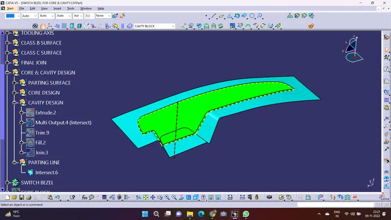
CORE DESIGN
Core:- A portion of the mold that goes inside a cavity to form the interior of a hollow part.
Core-Cavity:- A term used to describe a mold created by mating A-side and B-side into mold half's.
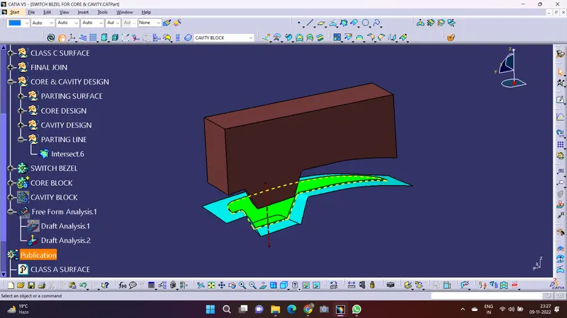
CAVITY DESIGN
- A mold is a hollow form typically made from stainless steel that has plastic injected into it to manufacture a plastic part.
- The plastic is inserted into the mold cavity, which is a hole in the mold shaped like the desired part.
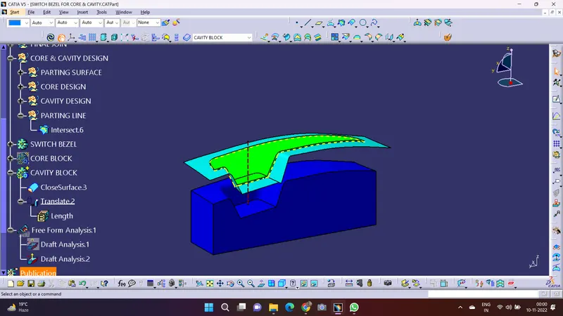
Views of the surface model in various orientation:
- Isometric View
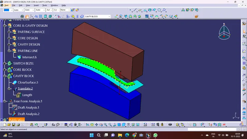
- Front View
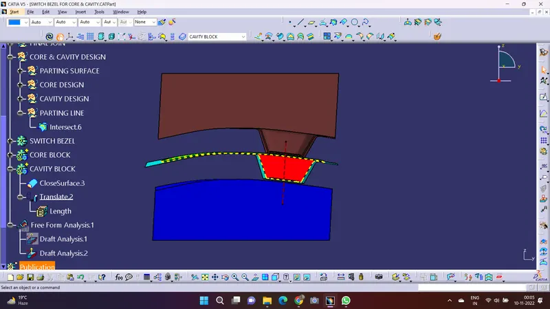
- Top View
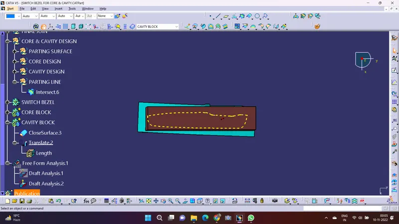
- Side View