Week 11 - Final project
AIM : AIM: To design the car door inner panel with reference to given Class-A surface by using given mastersection, creating attachment features and performing draft analysis to check the manufacturing feasibility of the component by using software CATIA V5.
INPUTS:
- CLASS A surfaces of the DOOR ARM REST, MAP POCKET, BOTTLE HOLDER and LOWER SUBSTRATE.
- Master section for the attachment features.
- Push clips for the assembly.
OBJECTIVES:
- Analysing the class A and performing necessary modification to obtain the modified class A.
- Creating the tooling axis for all the components .
- Performing draft analysis of class A surface.
- Creating the class B surface with the help of surface workbench.
- Creating the class C surface with necessary draft.
- Trimmimg the CLASS A,B AND C Surface for obtaining the final trim for all the components.
- Creating the closed body for all the components.
- Creating the attachments on the LOWER SUBSTRATE for assembly like DOG HOUSE, HEAT STAKES, AND RIBS.
- Creating the flanges on the other three components for the assembly purpose.
- Creating the Side core tolling axis.
- Performing the vigrous draft analysis and make sure all parts are clearing with positive and required draft.
- Assembly of the push pins over the dog house in assembly workbench.
- Final submission.
ANALYSING THE PROJECT:
- DOOR TRIM DEVELOPMENT IN CATIA V5.
About the software: CATIA V5
CATIA is the world’s engineering and design leading software for product 3D CAD design excellence.It is used to design, simulate, analyze, and manufacture products in a variety of industries including aerospace, automotive, consumer goods, and industrial machinery, just to name a few. It addresses all manufacturing organizations, from OEMs through their supply chains, to small independent producers.
If you stop and take a look around, CATIA is everywhere. CATIA is in the plane that just flew over, the car that just went silently by, the phone you just answered, and the bottle of water that you just finished.
Here, we have used the PART , SHAPE(GENERATIVE SHAPE DESIGN ) AND PRODUCT/ ASSEMBLY WORKBENCH.
DOOR TRIM OF THE AUTOMOBILE:
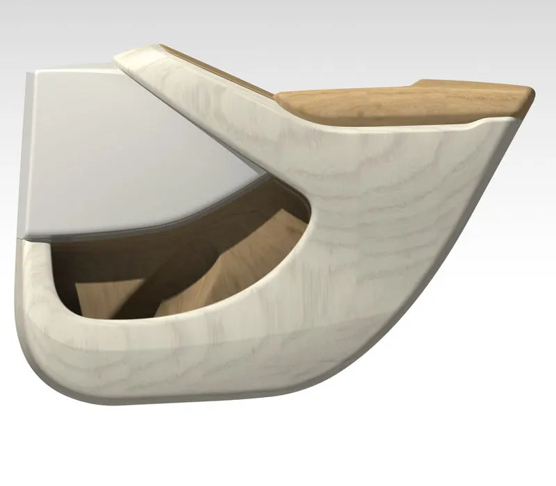
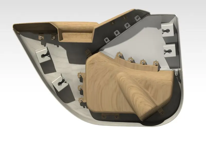
- Door panels serve as an interface between the interior of the car and the inner workings of the door, and between vehicle occupants and the door.
- They are expected to meet a variety of design specifications regarding safety, aesthetics, and functionality. In addition, they are expected to continue the materiall theme of the dashboard and pillars while concealing intricate electrical and mechanical components for operating locks, windows, and other features.
- The door panel has evolved from a simple two-part system of latch and simple winding mechanism to a more sophisticated enclosure. Doors currently have an inner full-width panel consisting of electronic windows, central locking system, and speakers.
- These panels typically consist of a foamed core covered with either textiles or plastics.
- Plastics is the core and soul of the door trim interior, one must have knowlege about the plastic being used and its cost associated with the molding and manufacturing.
CLASS A SURFACE :
- In automotive design application Class A surfaces are created on all visible exterior surfaces (ex; body panels, bumper, grill, lights etc.) and all visible surfaces of see-touch & feel parts in interior (ex: Dashboard, seats, door pads etc.).
Material Selection
The material can be used for manufacturing Door Panel is Acrylonitrile Butadiene Styrene (ABS). Because of its some features such as:
- The styrene provides the copolymer with a shiny, tough exterior.
- Provides quality surfaces and good resistance to chemical agents.
- A wide variety of adjustments can be made to enhance impact resistance, durability and heat resistance.
Also the Polyoxymethylene material can be used to manufacture the Door trim. It has the features called: high rigidity, yield strength and high stability in cold temperatures. Highly chemical- and fuel-resistant. Also POM is used to fabricate interior and exterior trims.
For manufacturing Door Trim component the injection molding method can be adopted. It would be the right manufacturing method. Because it is a right way to create the exact moulding for the required product. This is a common method is used to produce a high volume of plastic parts of automobiles. Products can also be made with increased flexibility to suit the needs of designers or engineers.
Class A,B & C Surface
Class A Surface:
It is the outermost aesthetic surface which is visible to customers (the outermost visible surface of a product).
Class B Surface:
It is the offset of the class A surface at a particular distance. The offset distance depends on the thickness between Class A and Class B surface. In Class B Surface, where the attachment features are built in and attached.
Here, the thickness given is = 2.5mm.
Procedures to build class B surface:
- Offsetted the joined surfaces from class A to 2.5mm inorder to create class B surface.
- Extrapolated the offseted surfaces inorder to make sure all the surfaces are in contact.
- Trimmed the offsets to get an output same as class A surface
- Fillets are given to the required edges based on the thickness and curvature of the class A fillets.
Class C Surface:
This surface connects the Class A and Class B surfaces. (Surface in between Class A & B surfaces)
Procedure to build Class C surface:
- Boundary of class A surface is extracted and then smoothcurved the boundaries if its required
- Also if needed Multi-Section Surface command can be used to create the Class C Surface
- Then that boundary is swept along with respect to Tooling Axis until it gets coincided with the offseted class B surface.
- Or else the boundary is swept perpendicular to the Class A Surface until it gets coincided with the offseted class B surface.
- Both the sweep surface and multi-section surface are joined together to form as a single one.
Joined and Closed Class A,B & C surface:
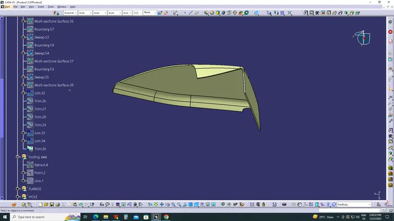
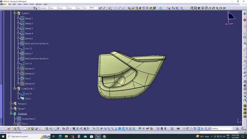
After creating class B & C surfaces, joining operation is done between class A and class C surfaces. Then, Class B surface is trimmed with joined Class A & C surfaces to get a whole closed single surface. Then in the part workbench using closed body command, a solid body is generated.
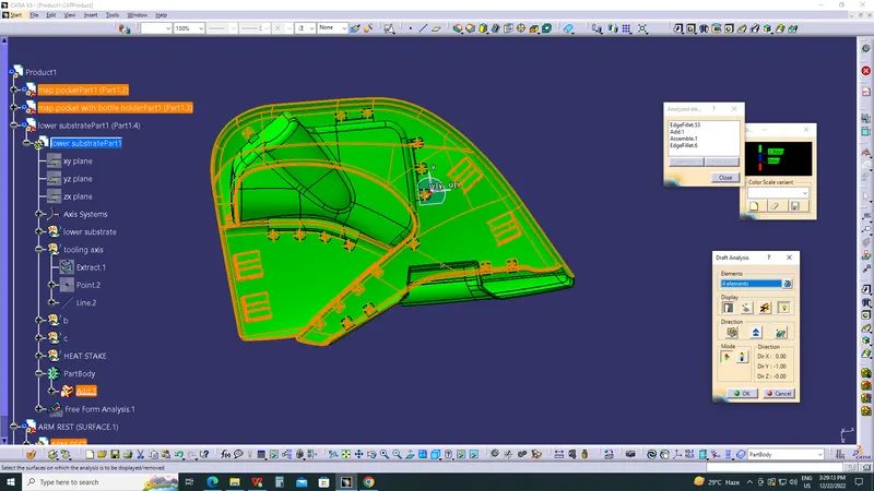
Draft Analysis:
In the criteria of making a plastic material, the mold should release the material when finished. if the mold surfaces are 90 degrees the material won't release from the mold because of friction due to contraction of material when cooled.The ejection of the part from mold depends on the draft. A zero draft can result in difficult or no ejection. It is recommended to add a draft of 3 degree or above inorder to remove it from the mold without any damage.
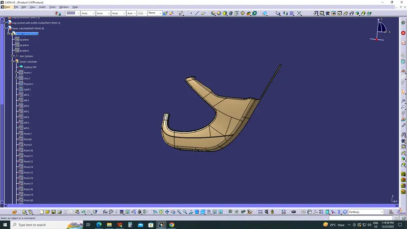
LOWER SUBSTRATE.
DOOR ARM REST.
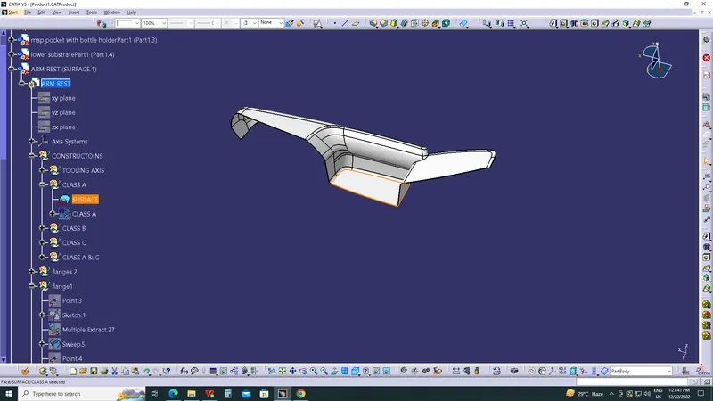
BOTTLE HOLDER .
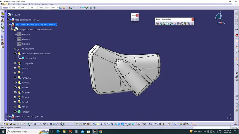
MAP POCKET.
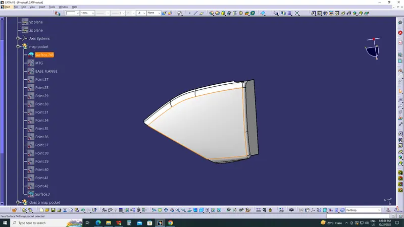
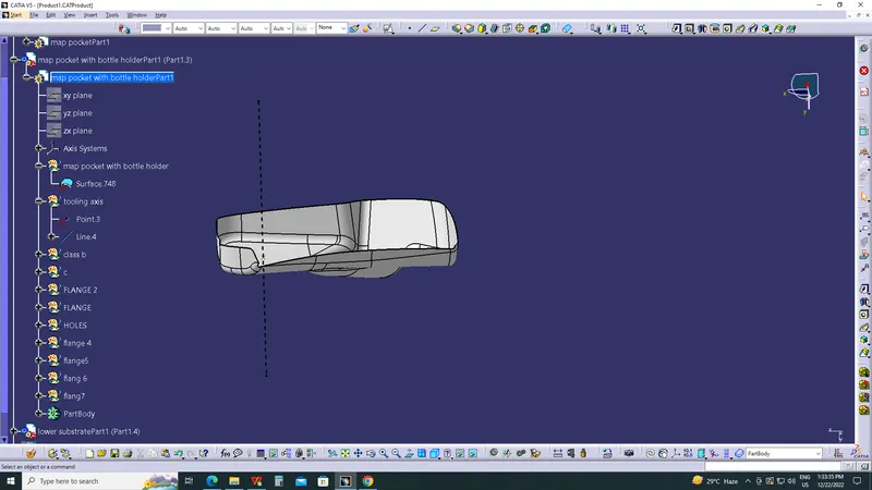
2)TOOLING AXIS CREATION :
- Tooling axis plays important role in plastic product manufacturing and designing, this axis decides the direction in which mould is going to work while production of the component.
- The main focus while deciding the tooling axis is clearing the component in the moulding in the same axis with the minimum use of the side core for producing the component, the side core usually adds up to the cost of the component.
- For the particular component X,Y and Z can be the possible direction for the tooling axis.
- You must specify the axis system by creating the point on the surface.
- With the help of the intersect in the YZ plane create the tooling axis in YZ plane .
- With the help of the intersect in the ZX plane create the tooling axis in ZX plane.
- The last step is to bisect the two tooling axis to obtain the main tooling axis of the class A surface.
TOOLING AXIS FOR LOWER SUBSTRATE
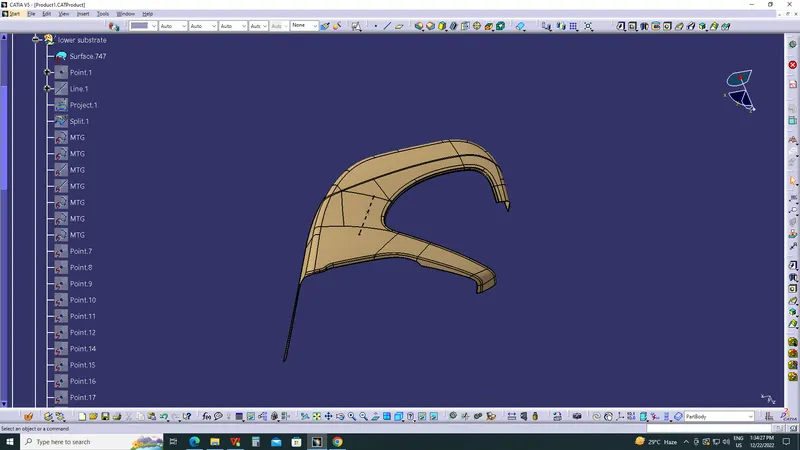
TOOLING AXIS FOR DOOR ARM REST
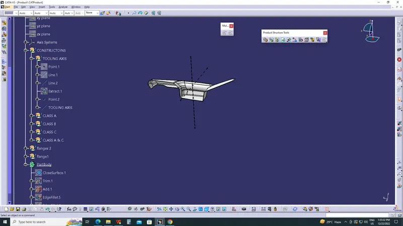
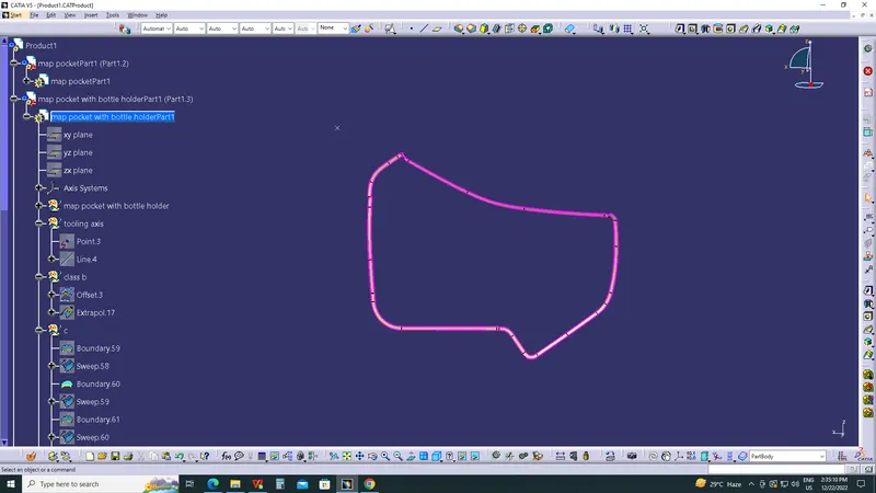
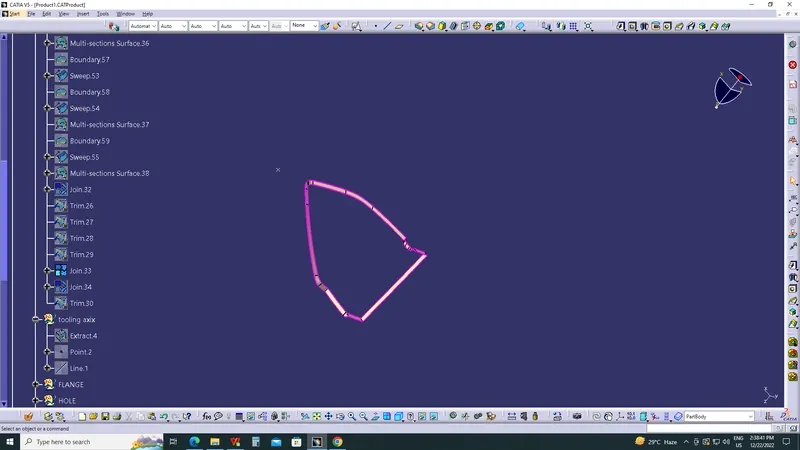
TOOLING AXIS FOR MAP POCKET
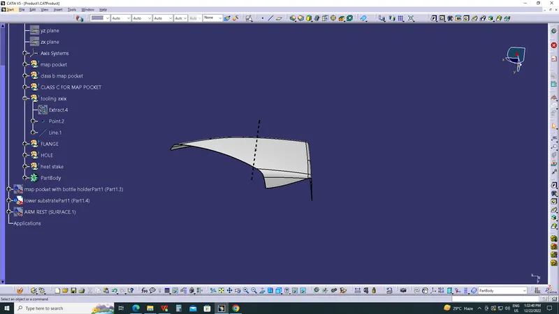
TOOLING AXIS FOR MAPPOCKET WITH BOTTLE HOLDER
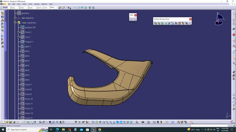
CREATING THE CLASS B SURFACE:
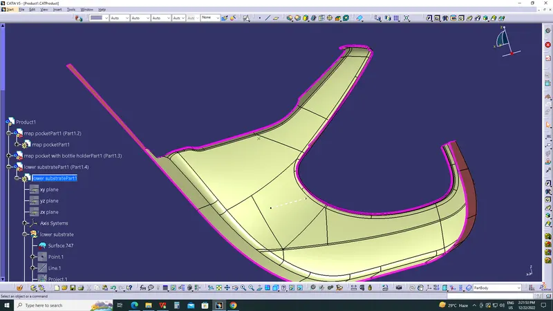
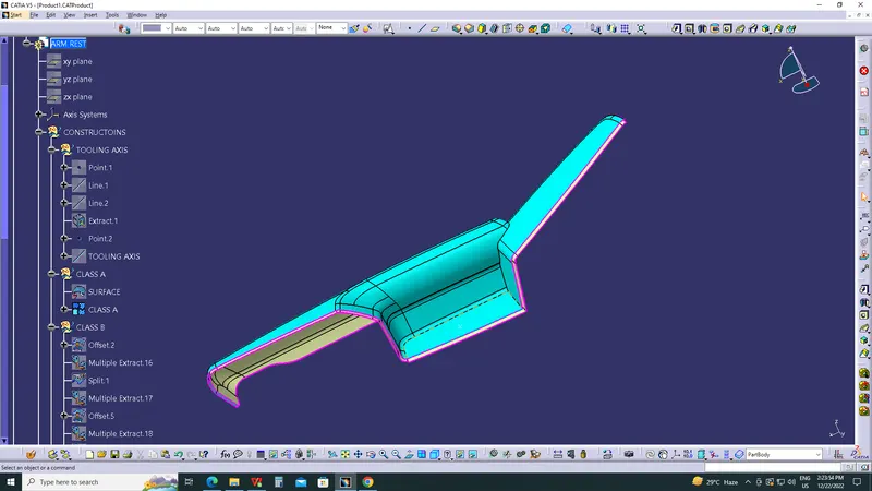
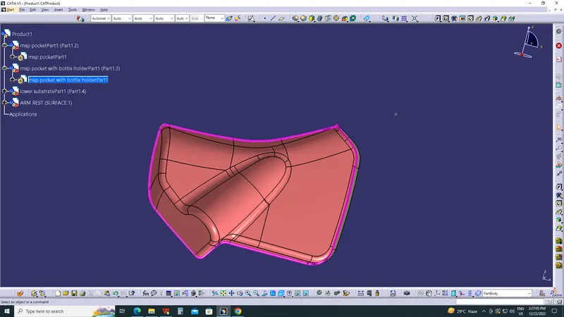
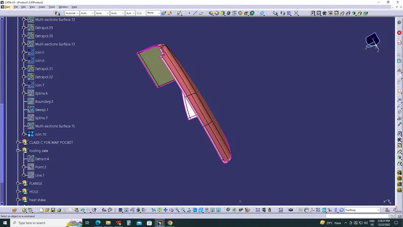
- Class B surface is the surface which is created with the help of class A surface as the reference.
- The the class B surface is the surface where all the necessary attachments and supports of the component is made .
- The main parts without the edge fillets are extracted and untrimmed and then they are extrapolated for better view.
- The extrapolated parts are then made offset with reference to the class A with the thickness of the component, here thickness of the component for base bracket is 2.5 mm.
- The offset surfaces are then trimmed to attain the class B surface.
- You can even directly offset the class A for obtaining the class B surface.
- The final class B surface must have the edge fillets similar to the class A and fillets must be given properly with a thought of maintaining same thickness throughout avoiding the flow line defects.
LOWER SUBSTRATE.
DOOR ARM REST.
MAP POCKET WITH BOTTLE HOLDER.
MAP POCKET.
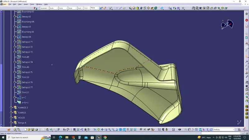
5)CREATION OF CLASS C SURFACE AND TRIM :
- The class C surface is the surface which is created to provide thickness to the class A surface with the help of class B surface.
- The class C surface is the middle portion of the class A and class B surfaces.
- The class C is created with the help of the sweep command in surface workbench.
- The class A surface's boundary is taken as profile (guide curve) and then tooling axis created is taken as direction of the sweep in subtype draft direction
- The draft angle for the sweep is 3 degrees.
- The holes are created using the same axis and draft angle.
- The attained sweep is joined with class A surface to obtain the class C surface.
- The final trim is obtained by trimming the class B with the class C surface.
- The final check to ensure the proper clossness of surface with the boundary command .
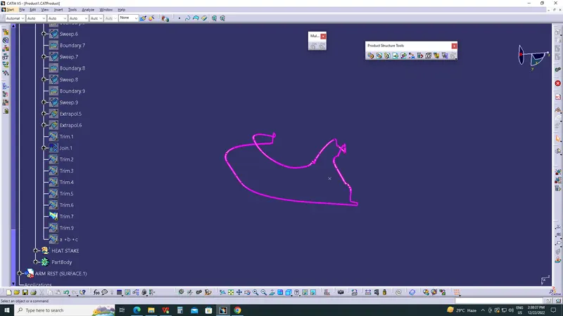
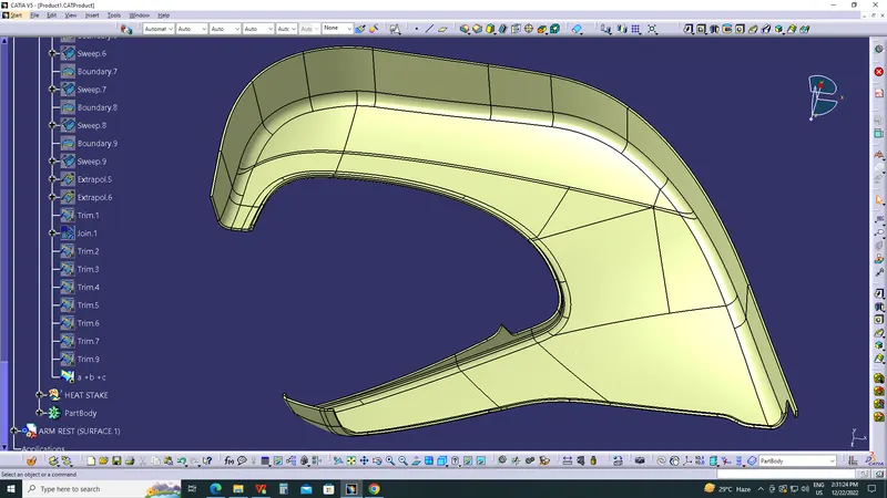
LOWER SUBSTRATE
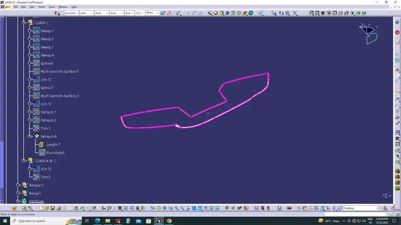
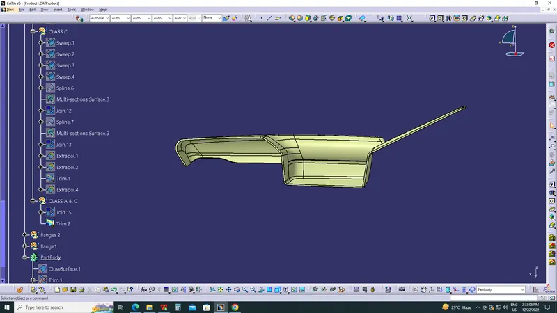
DOOR ARM REST
MAP POCKET WITH BOTTLE HOLDER
MAP POCKET
CLOSED BODY
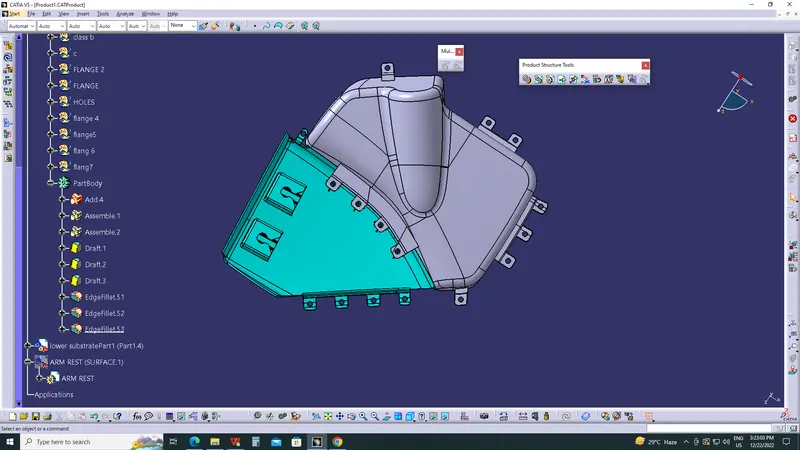
CREATING THE ATTACHMENT FEATURES FOLLOWING THE MASTER SECTION.
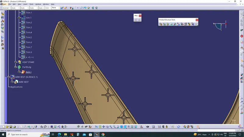
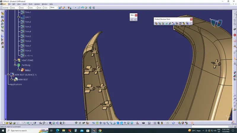
HEAT STAKES
- Heat Staking is a pulsed-heat process to join two or more parts out of which one at least is made of plastic.
- The process is to deform the plastic material using heat and force at a set process time.
- The bond is made by partially de-forming the plastic part in order to fix the other.
- Heat Staking makes it easy to bond metal to plastic and is commonly used in high volume/low cost applications such as automotive, IT and consumer appliances.
- Similar and dissimilar materials may be joined: metal to metal, plastic to plastic, metal to plastic
- Accurate control operating within a small process window
- Local heating resulting in no damage to surrounding materials
- Processing of glass-filled materials
- No mechanical vibration
- Many heat-stake shapes possible through custom designed tools.
RIBS
- The ribs provide economical stiffness and strength to the part without increasing the overall thickness of the part.
- The ribs are used as locating and arresting in the assembly as locators.
- Proper allignment in mating parts, slot and rib pair is long lasting other than screw pair which loosen up with time.
- Acting as stops or guide for mating the tilted headlamps.
- Rib designs includes.
- thickness, quantity, height , manufacturibility and location.
HERE WE HAVE USED THE LOWER SUBSTRATE FOR THE APPLICATION OF THE HEAT STAKES AND RIBS.
DOG HOUSE
- Dog house is the attachment feature which helps you to assemble things at certain heights and also resolve the plastic defects.
- There are plenty dog house design which can be used for assembly purpose but we will be using the one provided to ous by the resources.
- The master section or the enginnering drawing must be followed for creating the dog house.
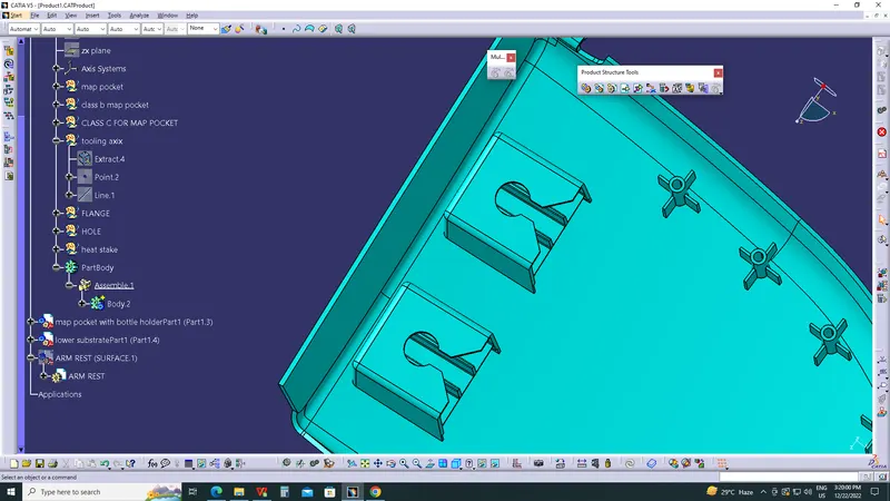
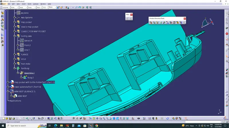
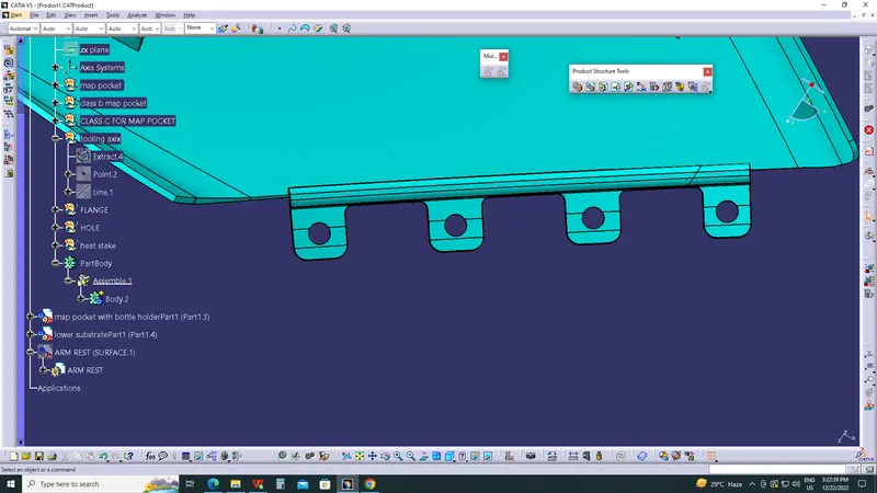
FLANGES ON THE COMPONENT
- These flanges will be build on the components for the fittment purpose with lower substrate.
- The hole at center will be guided along the heat stakes.
- Later top portion of the heat stake will be melted over it.
- The flange should rest on the supporting ribs on side .
DRTAFT ANALYSIS OF CLASS A SURFACES
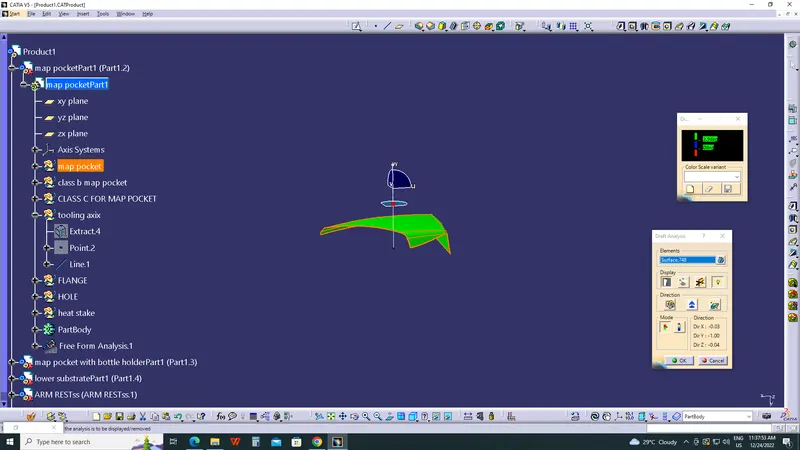
MAP POCKET
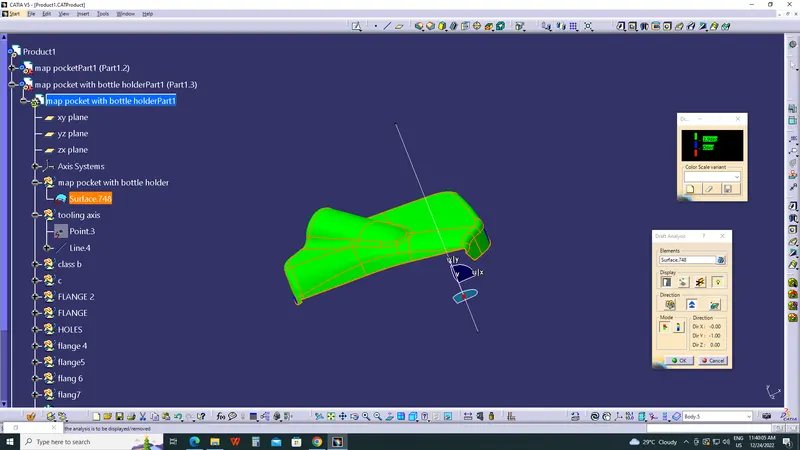
MAP POCKET WITH BOTTLE HOLDER
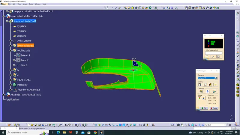
LOWER SUBSTRATE
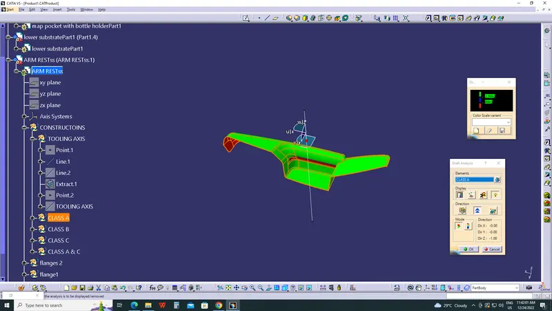
ARM REST
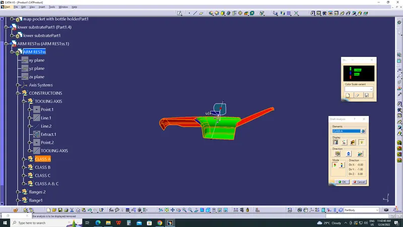
DRAFT ANALYSIS OF BSIDE FEATURES
MAP POCKET ENGINEERING FEATURES
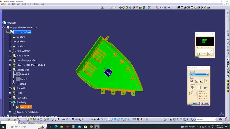
MAP POCKET WITH BOTTLE HOLDER ENGINEERING FEATURES
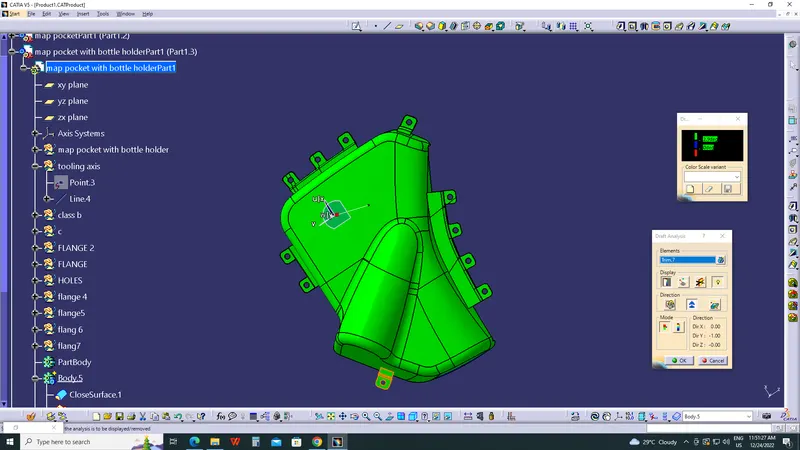
LOWER SUBSTRATE ENGINEERING FEATURE
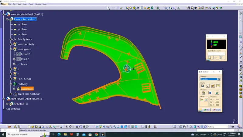
ARM REST ENGINEERING FEATURE
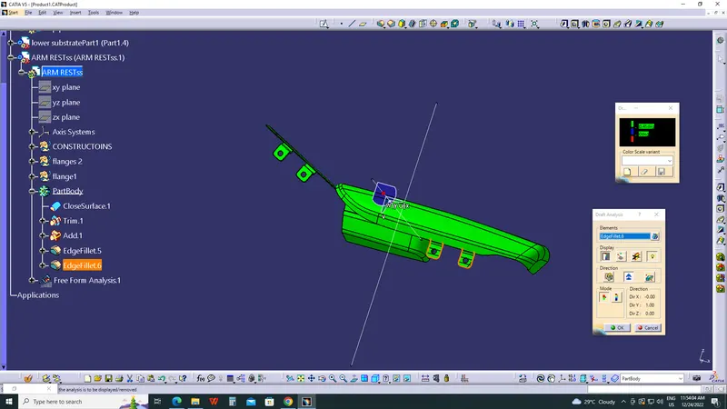
DRAT ANALYSIS of WHOLE BODY
- The draft analysis is done to ensure that the draft in permeasible with the design consideration.
- The draft analysis is done by changing the visualization mode to customize and select shading as material.
- The draft based feature enables us to visualize and examine the draft.
- The draft window is has two tables one is for examining the draft and other one is the colour code.
- The draft value is set in the colour code window with each colour having their own significance.
- The red colour indicates the positive draft less than minimum draft where as the green colour indicates the minimum draft.
- The blue colour indicates the negative draft.
- For visualizing the draft the compass is aligned with the tool axis direction and the cursor is then made clicked upon the surface for viewing the draft.
- The quick view in display window enables to examine the draft value throughout the surface.
- Here both class A and closed body are given the minimum draft as 3 degrees.
- The attachment feature are given draft of 0.5 degrees.