Week 8 - Challenge 4 - Bumper
AIM : To create the Bumper Design Plastic component through the given Class-A surface.
Objective
- To create a tooling direction.
- To perform draft analysis for given A-Surface and prepare the final close body.
- To design the Bumper plastic component by creating the B-Surface and C-Surface using the given Class-A surface.
- Take the Thickness of the component to be 3 mm.
Introduction :
The input of the product designer is in the form of the A-class surface. The job of the product designer is to create the B and C surfaces keeping all the aspects for the mold.
Class A Surface is
- Visible surface and aesthetic look.
- Surface with textures.
- Surfaces provided by customer(OEM).
- Don't have any features like(rib, snap, bosses, etc) on class A surface.
- Class A surface is made from scanned data with different software like alias etc.
- Surfaces which are having CURVATURE CONTINUITY IS CALLED class-A..
Class B surface is
- Invisible Surfaces.
- Surface mostly don't have textures.
- Surface needs to be created according to the class-A surface.
- Having all features(Rib,boss,snap etc) in B-side surface only.
- Surfaces which is having TANGENT CONTINUITY IS CALLED class-B.
Class A Surface : Check the connectivity of the Class A Surface Ensure that there is no gap between the component, using join command. We can visually check it or by clicking boundary command. It has a boundaries outer. Therefore first check completed.
Below fig 1 shown the given A-class surface.
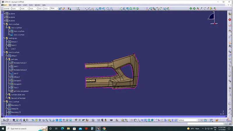
The given A-Surface having No gap as above fig shown. Hence boundary generated at the edges.
Procedure :
Tooling Direction for Plastic Part : Tooling direction is main consideration for plastic part and mold parts because it defines movement of mold part and possibility of plastic part to come-out from mold part (Core and Cavity).
- In Molding machine arrangement is given to open the mold along a direction which is known as Tooling Direction.
- In other words. The mold is built from two separate halves (Core and Cavity) and tooling direction basically define the direction of mold pulls apart.
- Tooling direction is known as primary direction.
Preparation of Tooling Direction
i just extracted the surface where number plate get placed and created a point exact centere of the extracted surface and through that point i draw a line in such a manner it should be normal to surface
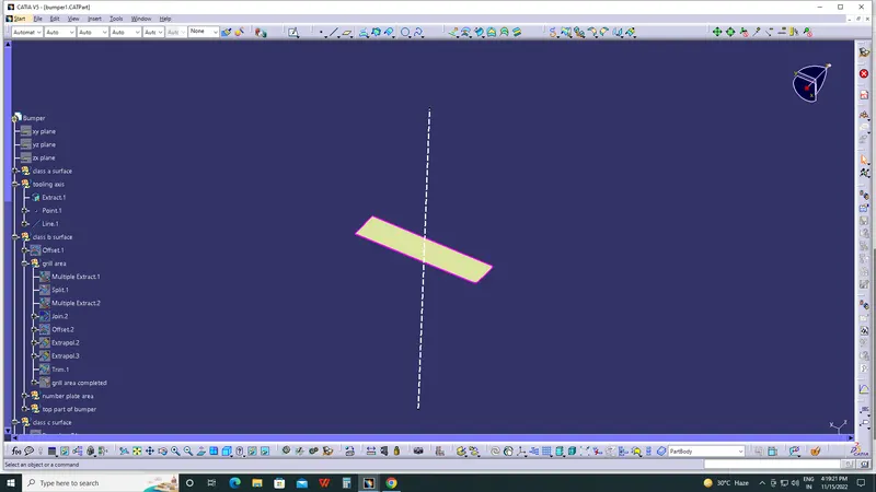
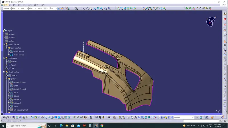
DRAFT ANALYSIS OF CLASS A SURFACE
The Draft Analysis is a command enables you to detect if the part you drafted will be easily removed. This type of analysis is performed based on colour ranges identifying zones on the analysed element where the deviation from the draft direction at any point, corresponds to specified values.
Draft analysis is done after determining the tooling axis, draft analysis is used to check whether the minimum draft (3 degrees) is maintained or not.
- Procedure for performing the draft analysis are as follows
- Change the view mode of the component to be in customized parameter mode and then select the shading mode as materials.
- Then click on use the compass to define the current drafting direction and then drag and align the compass on the Tooling axis.
- Then lock the draft direction and perform draft analysis by clicking on the component.
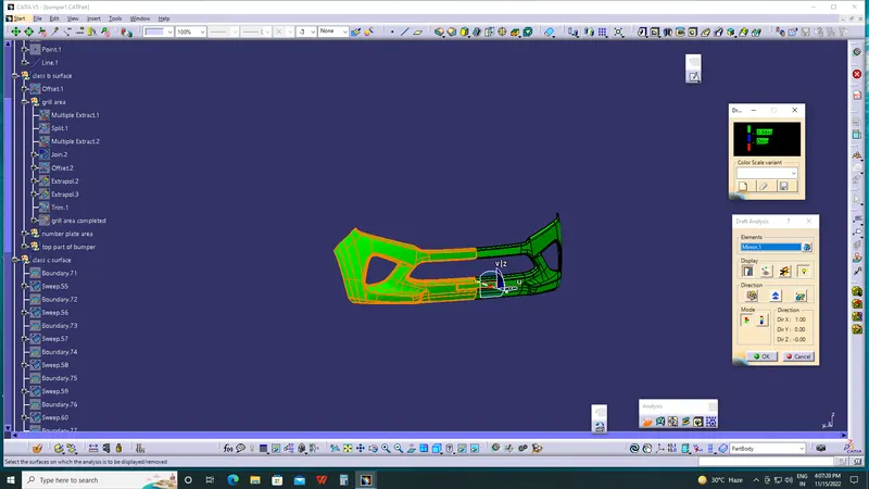
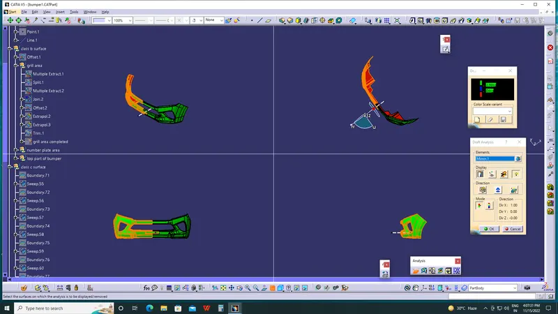
- The green colour shows the positive daft tooling direction and the given surface passes the draft analysis.
- Click on the analyses under the running point to check the draft analysis on the individual faces. It shows how much draft on specific points when we move the cursor point.
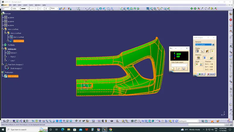
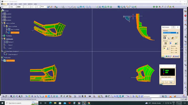
- Then lock the draft direction and perform draft analysis by clicking on the component.
SURFACE-B CREATION
Class-B surface means thickness of a part it is not visible and is inside part. In other words, Class-B surface is a surface below a certain thickness from the class-A surface. This is the surface that contains engineering aspects of a model.
- Offset the class-A surface to 3mm inward direction.
- Rework on the patches and discontinuity of the offset surfaces using the features like extract, multi-extract, sweep, multi-section surfaces, extrapolate.
- To ensure the continuity of the Class-B surfaces check the boundary command to find out the boundary.
- Hence class-B surface creation is done.
- First i done operation on grill area
- secand on number plate
- third on top portion of bumper
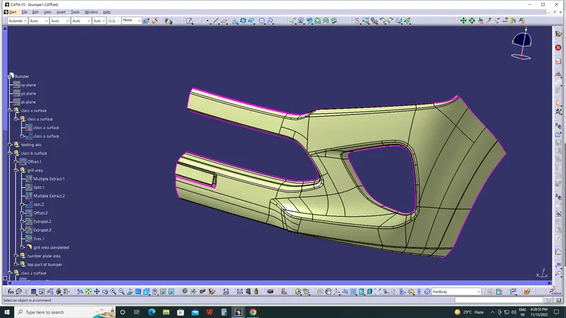
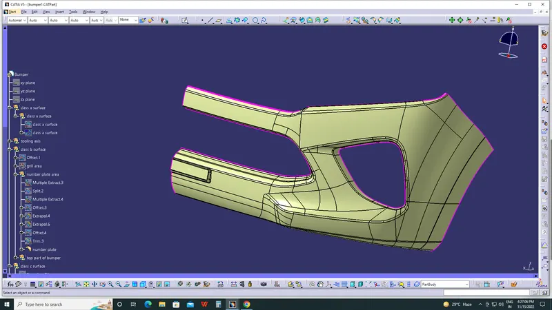
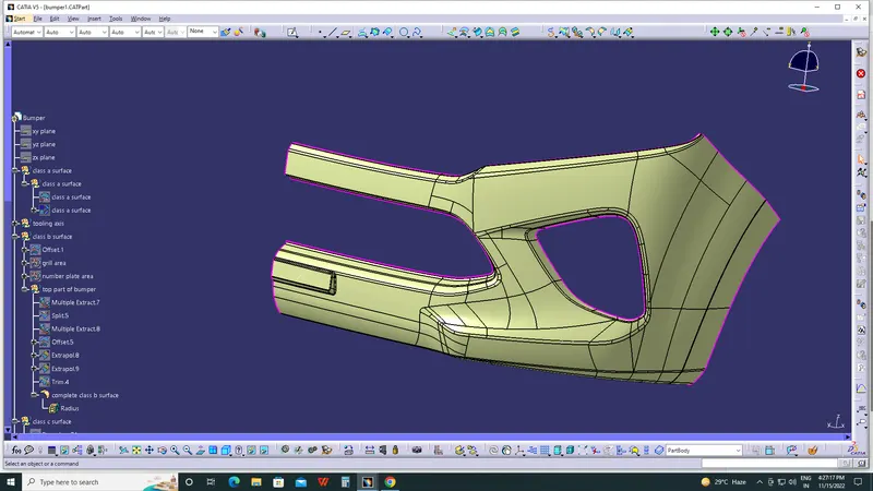
SURFACE-C Creation
Surface that joins class-A and class-B surfaces is class-C surface. Class C is often specified for interior surfaces not readily visible, surfaces that will be covered by another part when assembled
C-Surface connects the class A-Surface and B-Surface. It is created using Sweep command. Boundry of the class A-Surface is swept in 90 degree angle
- Extrapolate and trim off the sweep surface corners at the required edges.
- Join the sweeps using the join command and the class-c surface is created.
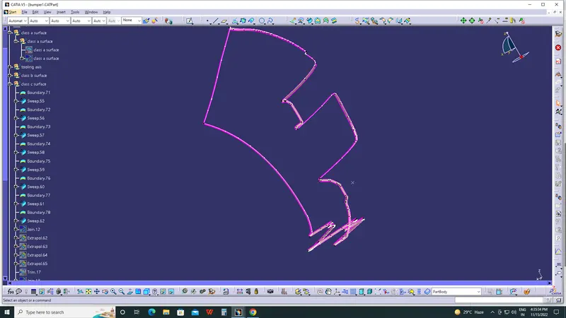
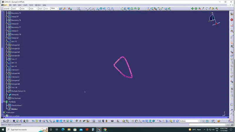
Creating the final surface of Bumper
- First step is to join the CLASS-A surface with CLASS-C surface.
- Then Trim the Joined surface with CLASS-B surface to achieve the final Bumper surface.
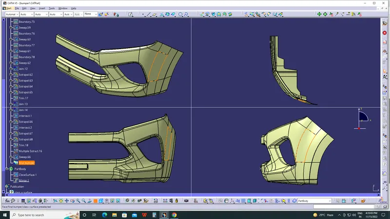
Go to the part design work bench and using the close surface command create the base bracket solid part body
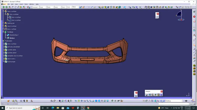
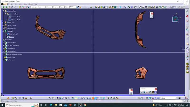
3D Part model in various orientations (Isometric, Front, Side, and Top View)
Draft analysis of the Final part body
Same procedure for the draft analysis of CLASS-A surface is followed.
- Change the view mode to material shading
- Align the Compass with Tooling axis.
- Lock the draft direction and perform the Draft analysis.
Conclusion
I have successfully created the class-B and Class-C surfaces of Bumper using the given Class-A surface along with the tooling axis in the CATIA surface workbench.
PLASTIC MATERIAL WHICH USED IN MANUFACTRUING OF BUMPER
ABS plastic is chemical- and heat-resistant and offers good protection against dents, it's widely used by automobile manufacturers as original equipment for trim, bumper covers, and some body panels.
ABS is an acronym for acrylonitrile butadiene styrene. This is a strong thermoplastic polymer commonly used on the exterior of vehicles in the form of mud flaps, fender flares, trim, and so on.