Week 11 - Final project
AIM:
To create a door interior part from the inputs of class A surface along with master section by following the design rules followed in tier 1 and OEM industries in catia v5
SOFTWARE USED:
CATIA V5
OBJECTIVES:
- Create a sketch by using Positioned sketch
- All the should be sketches should be Iso-Constrained
- Ensured Proper Tree Structure
- Geometrical sets should having a proper name based on the sketches present inside of it
- Create thickened part using master section for reference
- Create the mounting features as per design guidelines in the industry and with master sections
- Creating of Draft analysis & Tooling analysis
- Creation of parting lines and check tooling feasibility
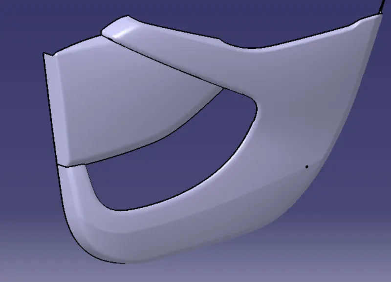
- INPUT OF CLASS A SURFACE
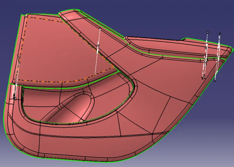
DRAFT ANLAYSIS:
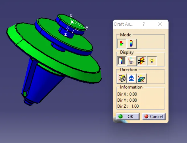
Draft analysis in catia is a command that is used to detect if the part you drafted will be easily removed from the mold. it is performed based on color ranges identifying zones on the analyzed element.
Most of the industries is using minimum draft angle is 3 degree
CREATION OF TOOLING AXIS – LOWER SUBSTRATE
Since the input class A surface is containing four different parts(class A). So class b and c for all the surface has been created in separate catpart. Also performing draft analysis and tooling axis separately. finally all the surface have assembled together in one catproduct.
PROCEDURE:
- Check all the boundary whether it has connected or not.
- Check the model visually & choose the best tooling direction which should be easy for draft.
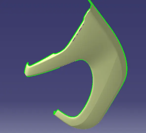
CREATION OF TOOLING AXIS – BOTTLE HOLDER
PROCEDURE
- Check all the boundary whether it has connected or not.
- Check the model visually & choose the best tooling direction which should be easy for draft.
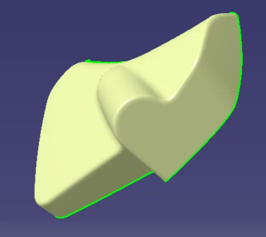
CREATION OF TOOLING AXIS – ARMREST
PROCEDURE:
- Check all the boundary whether it has connected or not.
- Check the model visually & choose the best tooling direction which should be easy for draft.
After analyzing the above model, there is an chance for undercut when we consider tooling axis from z.so we have to create tooling axis on x,y and also z.
PUSHPIN:
- Draw a sketch of pushpin by using positioned sketch command.
- Ensure that the sketch is iso constrained.
- Shaft the sketch to 360 degree by using shaft command.
- Add minimum fillets to pushpin.
- Create a sketch to groove the pushpin for 30 degree.
- Use ciruclar pattern command for groove
FINAL PRODUCT: