Week 11 - Final project
Aim:- To development of a Door Trim panel solid body from the class A
Objective:- To create a solid Door Trim panel from a class A surface with a master section. Create the side attachment feature as well, adhering to design principles.
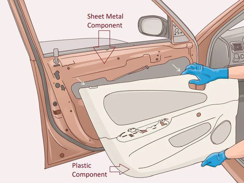
Introduction The door panel serves as a conduit between the car's interior and the door's internal mechanisms. For ease of design, the door panel is typically separated into components like an arm rest, a map pocket, and a lower substrate. These have one of the strictest specifications among the car's interior components. This needs to be built to withstand the weight while having a thickness of no more than 2 mm and protecting the occupants in crashes.
Class A surface
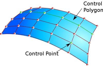
In the design of automobiles, Class-A surface in any of a number of high-quality, efficient surfaces. Digital applications that are computer-aided are used to create Class-A surfaces. Digital sculptors are another name for class-A surface modellers used in the business.
Class B surfaces
Class B surfaces are engineering surfaces that are either hidden from view or frequently found behind Class A surfaces.The primary engineering elements, such as screw bosses, ribs, snaps, stiffeners, and fixations, are present on these surfaces. Since B surfaces are invisible to the eye, they also lack any attractive styling content and textures.
Class C Surface:
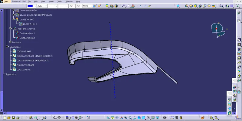
Connectors between Class A and Class B surfaces are Class C surfaces. Along the tooling axis, this surface links the A and B surfaces. It includes the design-approved drafts. In essence, it is the surface that is thicker between surfaces A and B.
Tooling Axis:
The direction in which the Mold opens and closes is known as the tooling axis. Typically, part draughts are provided along this axis.
Design Methodology to create door trim :-
1. Draft Analysis of class A surface
2. Creating class B surface
3. Creating class C surface
4. Creating Solid body
5. Creating Master section (Flanges, Heat stake, Locators)
6. Draft analyis of the components.
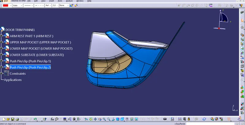
The door panel is divided into four parts for easly to design. There are,
- Door Arm Rest.
- Lower substrate.
- Upper Map Pocket.
- Lower Map Pocket.
1. Door Arm Rest
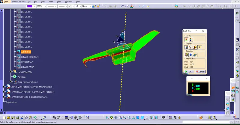
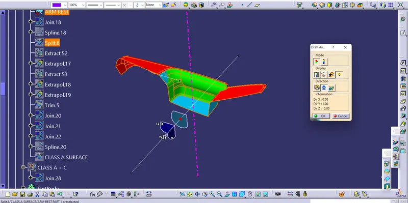
As we receive the Class A surface from the team, Check the discontinuity in the surface using the boundry command. create tooling axis by extracting a plain surface and create a point on its center for Axis system creation.Additionally, the walls of the input Class A are at a negative angle to the tooling axis.As it would be extremely challenging to draw from the moulds, this might be a problem for producing the component.Therefore, this design must take into account several side tooling options.
the below image shows the draft analysis of class A surface
Class B surface
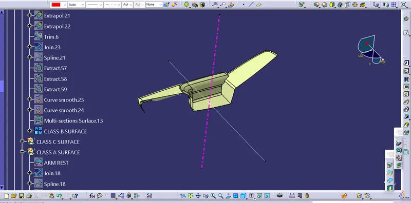
The B surface is given an offset to the thickening of the component and then inspected and patched if any surface irregularities exist in according with the Class A.
Class C surface
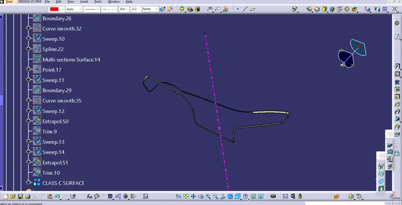
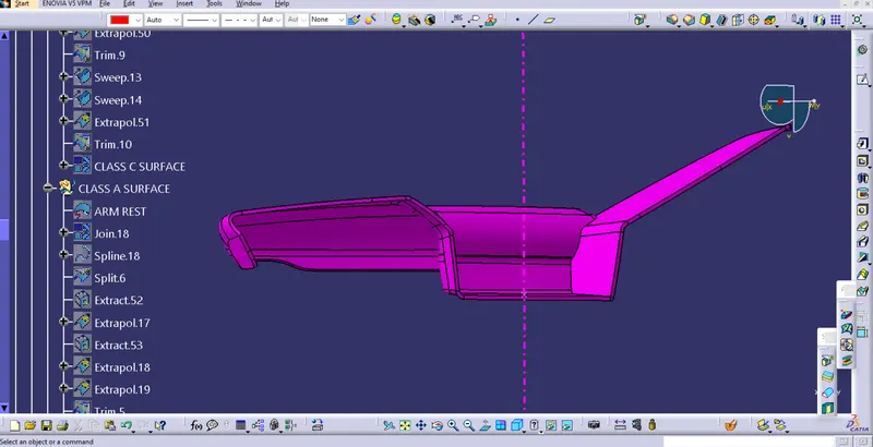
Convert the Class A border to a Smooth Curve.To the Class A, sweep the curve sweep value must be higher than the necessary portion thickness.Figure displays the sweep that was achieved.
To establish a single surface entity, join the Class A Surface and the Class C Surface together.
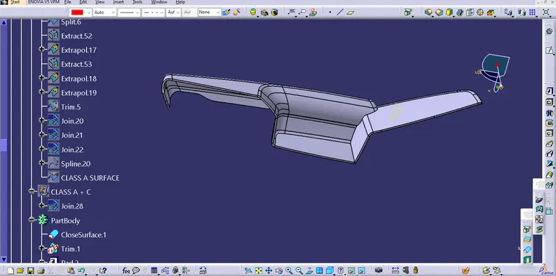
The enclosed surface is created by firts joining the class A and C surface and then triming the extrapolated surface of B from the class A and C
Closed Surface :-
Make the final trim to solid part using close surface.
2) Lower Substrate :-
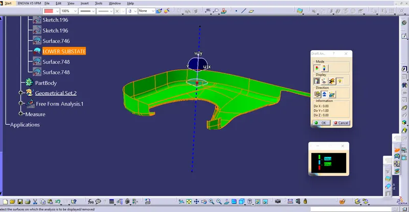
Check the discontinuity in the surface. Create the tooling axis by extracting and create the point to check the draft analyis
Class A surface
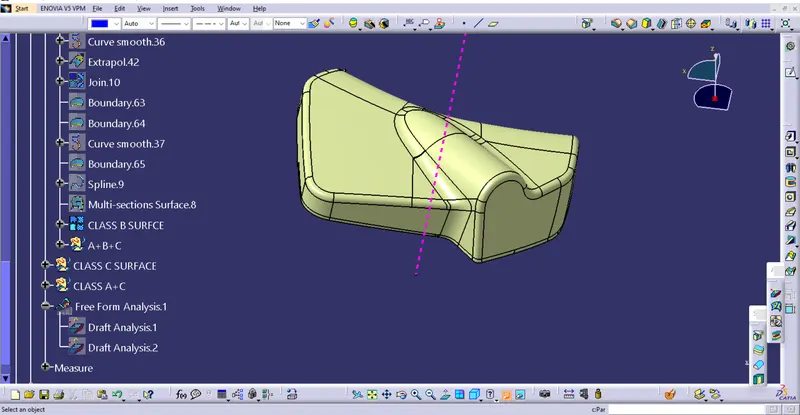
Class B surface of lower substate
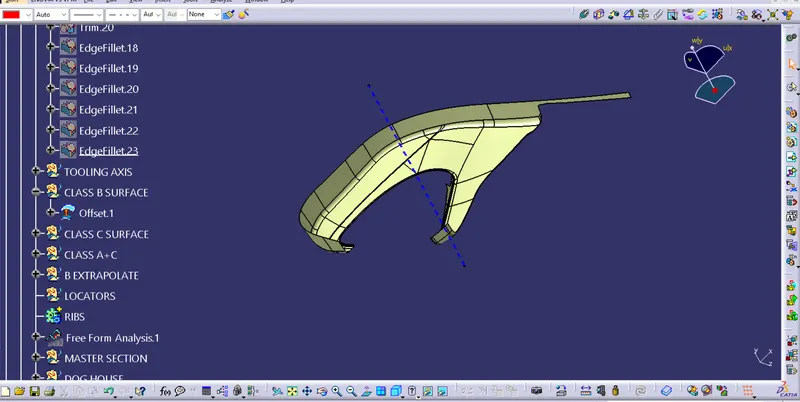
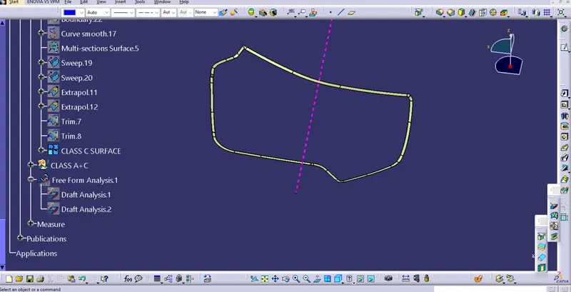
class C surface
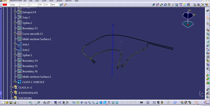
Enclosed body of lower substate
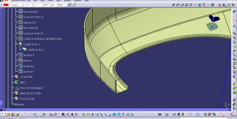
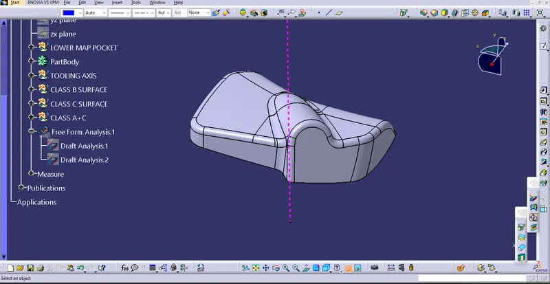
solid body
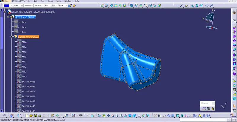
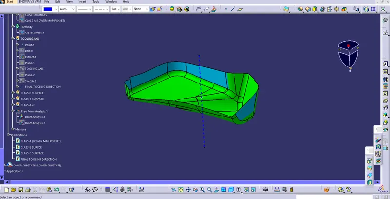
Lower map pocket
class A surface
Draft analysis of class A surface of lower substate
Class b surface
Class C surface
Solid body surface
4. Upper Map Pocket
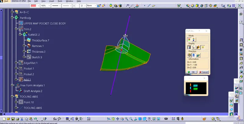
Draft analysis of class A
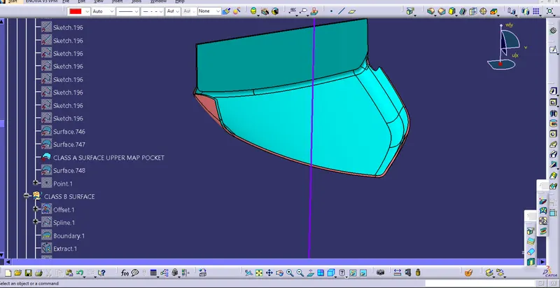
Class b surface
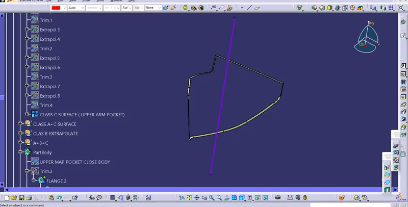
C surface
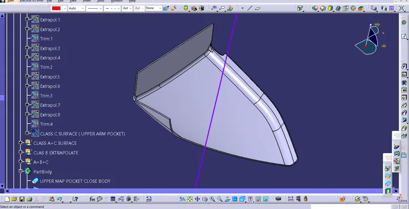
Solid body of the upper map pocket
B SIDE FEATURES:
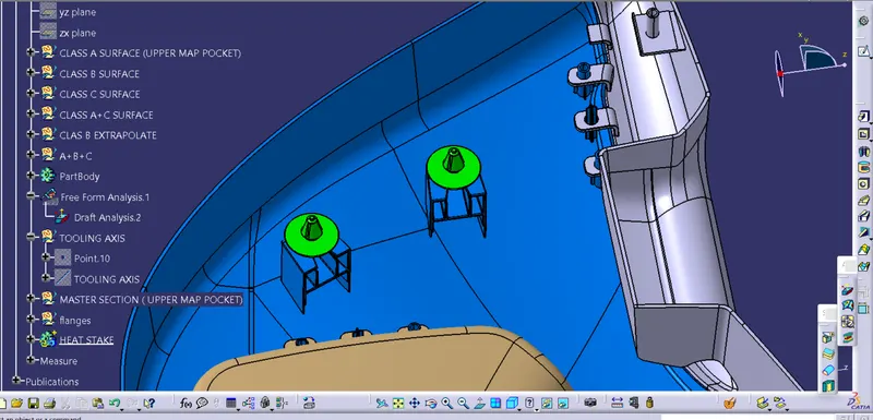
The engineering features are now being produced on the component's B side surface. These are created using the master section's already provided input. Below is an illustration of the master section and its components.
We can understand the characteristics that need to be created by breaking down the master section into its component parts
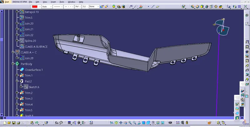
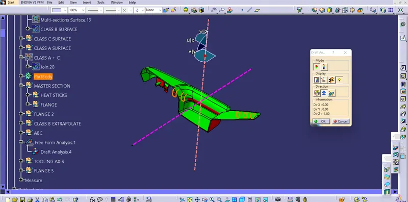
Arm rest feature
In arm rest the3 flanges are created with the hole that are to be extruded from the B surface These serve as a place to keep the heat stakes as well as the locators to find and mate the components
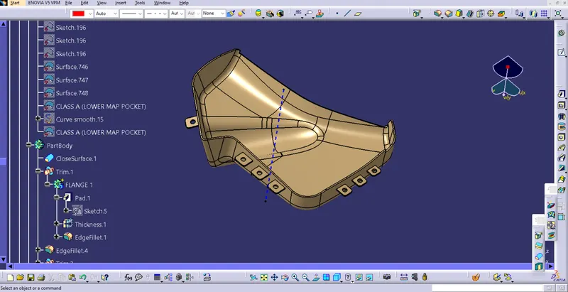
Lower map pocket feature
here & flanges are created in which heat stake and locators are attached
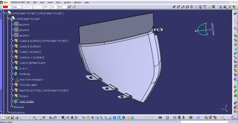
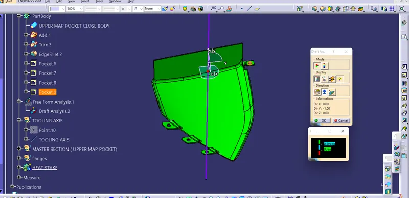
Upper Map pocket
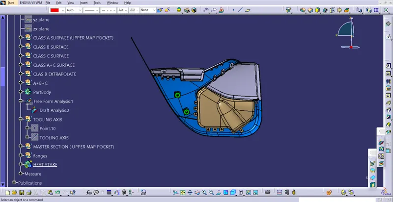
In upper map pocket the heat stake and flange is extracted from master section and provided with 3 flanges on one side and 1 on other side
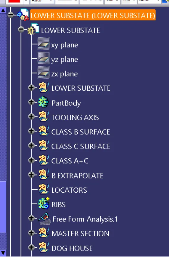
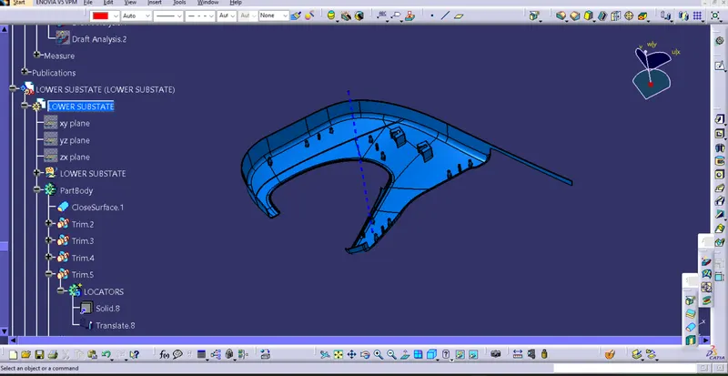
Lower Substate
The lower substate is provided with the heat stake and locators features and 2 dog house
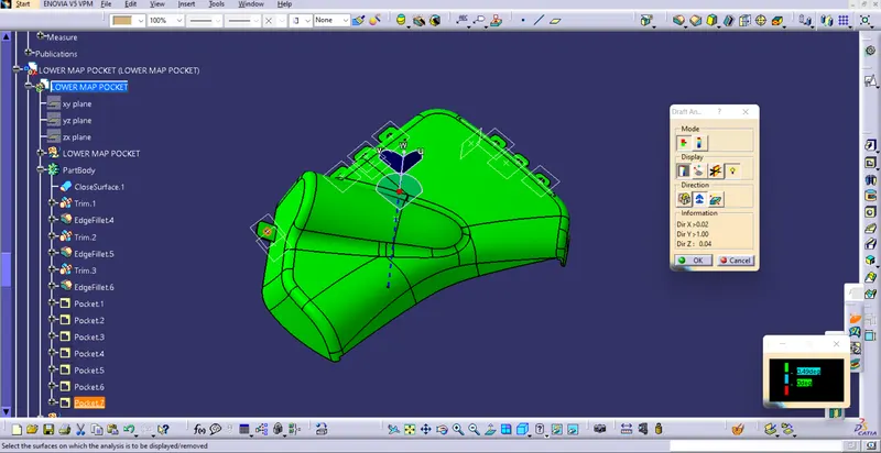
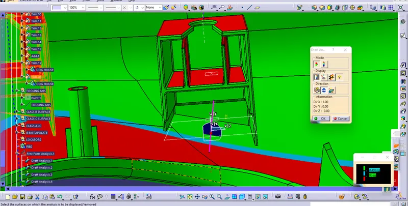
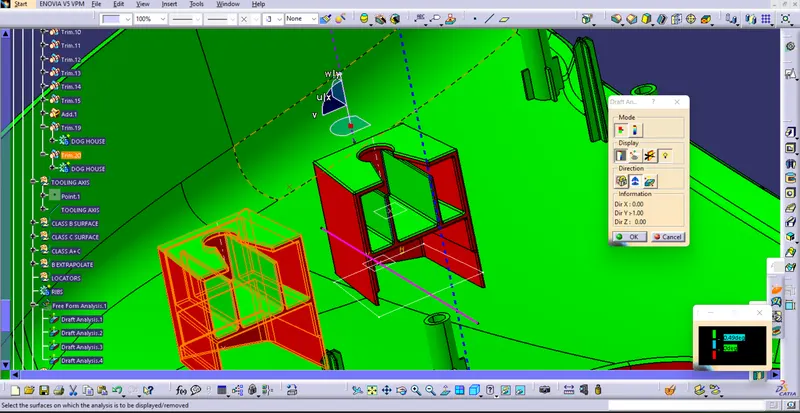
Draft analysis of engineering features
Then, in order to adhere to the design requirements and the drafting angles, engineer features are also required.
As we can see, the tooling direction is being cleared by the lower map pocket with the engineering characteristics.
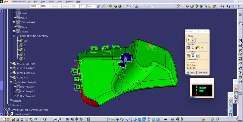
Draft analysis of lower substate
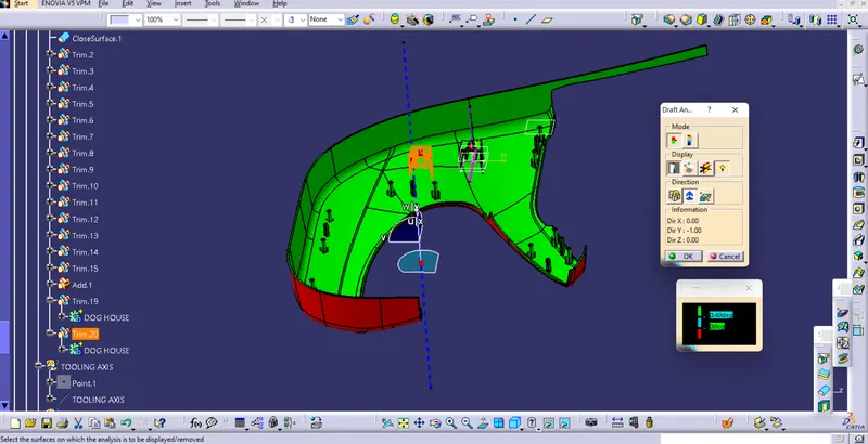
Upper map pocket features draft
Arm rest engineering features draft analysis
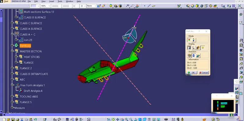
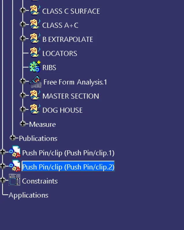
The dog house and push pins are then matched and coincided for the final assembly.
DOOR TRIM PANEL:
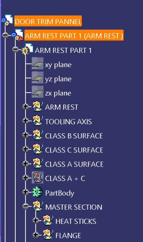
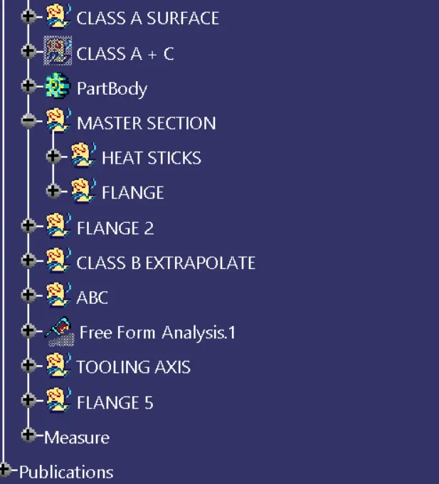
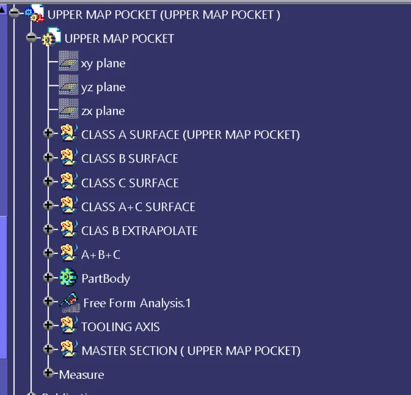
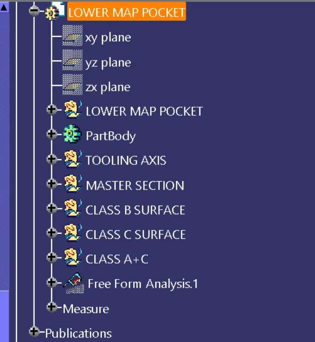
Tree structure