Week 11 - Final project
FINAL PROJECT REPORT
In this project i was provided with Class A surface of door trim panel which is consisting of 4 parts namely Armrest, Map pocket, Bottle holder and Lower substrate , these Class A surfaces are converted into part body and assembly features like flanges, heatstakes , locators and doghouse are created on top of these parts for the assembly.
ARMREST CREATION
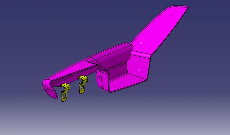
Class A of the armrest is offsetted to 2.5mm to obtain B surface, then the B surface is fixed by doing necessary patchings using multisurface and extrapolation + trimming. After this Class C surface is created with reference to the Class A by creating a boundary and using sweep function to obtain Class C surface and later this surface is joined together to get combined AC surface , after this the B surface is extrapolated to the required extend to obtain a exeeding intersection with the AC surface which is later trimmed together to obtain a closed part, this part is later converted into a body by using closed body function. Assembly features like flanges are then drafted on the desired surfaces and made into a part by closed body function and then union trimmed with the main body keeping the required surface.
DRAFT ANALYSIS OF ARMREST
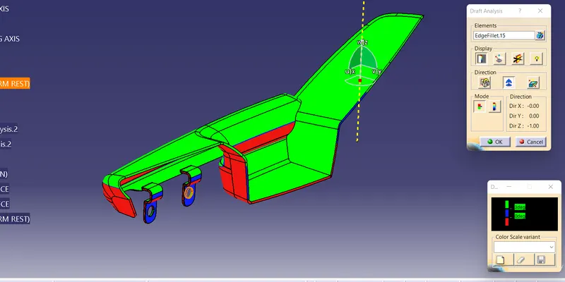
Draft analysis is done to check if the body is drafted with a nominal draft angle and if only this will go through the manufacturing process, to carry out the draft analysis we take the draft analysis option and click on the axis symbol to obtain an axis which is then dragged and placed on the tooling axis and locked, after this the main body is clicked to get a diffrent color than the main body this is according to the color scheme given, here green color shows 3 degree draft and is perfect for manufacturing.
BOTTLE HOLDER CREATION
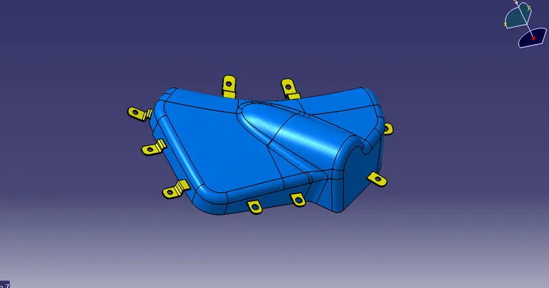
Class A of the bottle holder is offsetted to 2.5mm to obtain B surface, then the B surface is fixed by doing necessary patchings using multisurface and extrapolation + trimming. After this Class C surface is created with reference to the Class A by creating a boundary and using sweep function to obtain Class C surface and later this surface is joined together to get combined AC surface , after this the B surface is extrapolated to the required extend to obtain a exeeding intersection with the AC surface which is later trimmed together to obtain a closed part, this part is later converted into a body by using closed body function. Assembly features like flanges are then drafted on the desired surfaces and made into a part by closed body function and then union trimmed with the main body keeping the required surface.
DRAFT ANALYSIS OF BOTTLE HOLDER
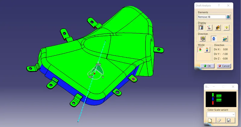
Draft analysis is done to check if the body is drafted with a nominal draft angle and if only this will go through the manufacturing process, to carry out the draft analysis we take the draft analysis option and click on the axis symbol to obtain an axis which is then dragged and placed on the tooling axis and locked, after this the main body is clicked to get a diffrent color than the main body this is according to the color scheme given, here green color shows 3 degree draft and is perfect for manufacturing.
CREATION OF MAP POCKET
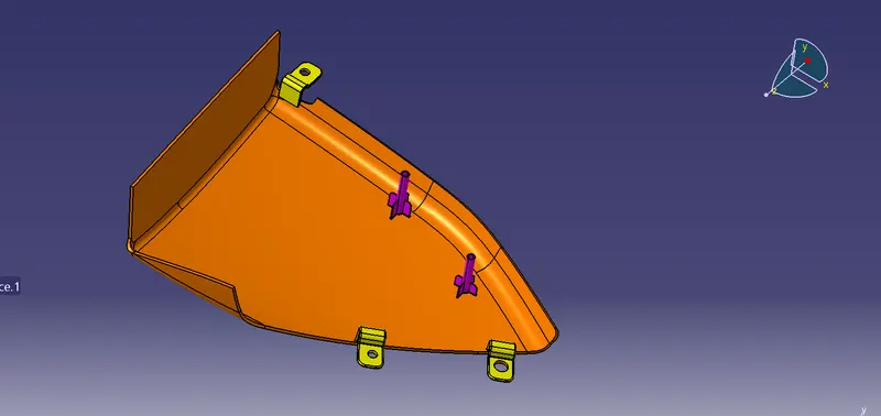
Class A of the bottle holder is offsetted to 2.5mm to obtain B surface, then the B surface is fixed by doing necessary patchings using multisurface and extrapolation + trimming. After this Class C surface is created with reference to the Class A by creating a boundary and using sweep function to obtain Class C surface and later this surface is joined together to get combined AC surface , after this the B surface is extrapolated to the required extend to obtain a exeeding intersection with the AC surface which is later trimmed together to obtain a closed part, this part is later converted into a body by using closed body function. Assembly features like flanges and heatstakes are then drafted on the desired surfaces and made into a part by closed body function and then union trimmed with the main body keeping the required surface.
DRAFT ANALYSIS OF MAP POCKET
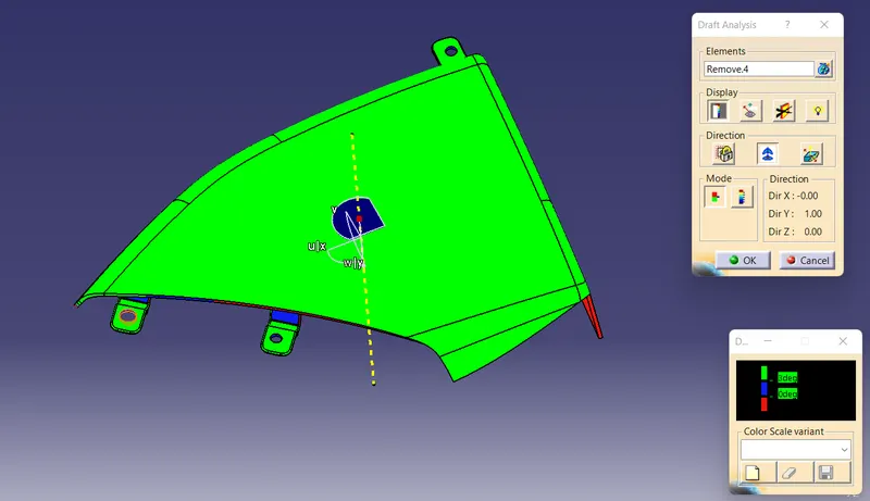
Draft analysis is done to check if the body is drafted with a nominal draft angle and if only this will go through the manufacturing process, to carry out the draft analysis we take the draft analysis option and click on the axis symbol to obtain an axis which is then dragged and placed on the tooling axis and locked, after this the main body is clicked to get a diffrent color than the main body this is according to the color scheme given, here green color shows 3 degree draft and is perfect for manufacturing.
LOWER SUBSTRATE CREATION
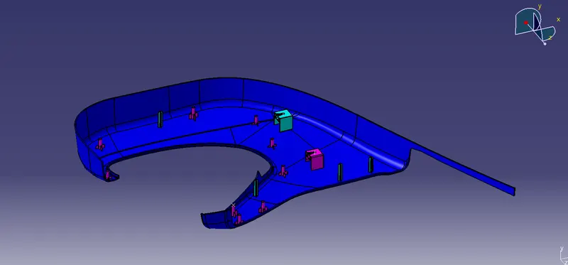
Class A of the bottle holder is offsetted to 2.5mm to obtain B surface, then the B surface is fixed by doing necessary patchings using multisurface and extrapolation + trimming. After this Class C surface is created with reference to the Class A by creating a boundary and using sweep function to obtain Class C surface and later this surface is joined together to get combined AC surface , after this the B surface is extrapolated to the required extend to obtain a exeeding intersection with the AC surface which is later trimmed together to obtain a closed part, this part is later converted into a body by using closed body function. Assembly features like flanges and heatstakes, locators and doghouse are then drafted on the desired surfaces and made into a part by closed body function and then union trimmed with the main body keeping the required surface.
DOG HOUSE CREATION
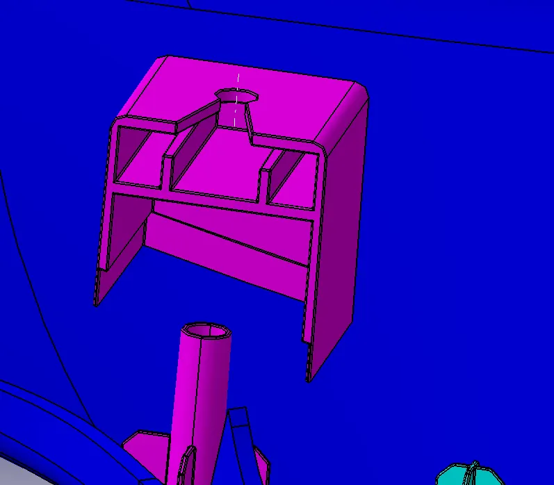
Doghouse is created by extracting a point in the surface and creating a plane on it , then a rectangle is drafted, extruded and thickened and after this the part is shelled and later a inside surface is drafted by creating a new plane inside and then this sketch is extruded, thickened and union trimmed with the doghouse and on top of the dog house the pushpin hole is sketched and removed to get a final body and then the doghouse is union trimmed with the main body.
DRAFT ANALYSIS OF LOWER SUBSTRATE
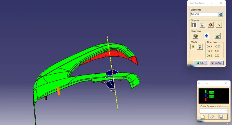
Draft analysis is done to check if the body is drafted with a nominal draft angle and if only this will go through the manufacturing process, to carry out the draft analysis we take the draft analysis option and click on the axis symbol to obtain an axis which is then dragged and placed on the tooling axis and locked, after this the main body is clicked to get a diffrent color than the main body this is according to the color scheme given, here green color shows 3 degree draft and is perfect for manufacturing.
DRAFT ANALYSIS OF DOG HOUSE WITH MAIN TOOLING AXIS
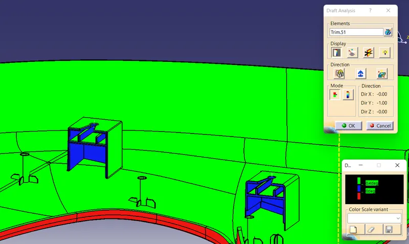
This draft analysis is done with the main tooling axis , as it is shown in green the body is given 0.5 degree draft angle and it is suitable for manufacturing
DRAFT ANALYSIS OF DOG HOUSE WITH SIDE CORE AXIS
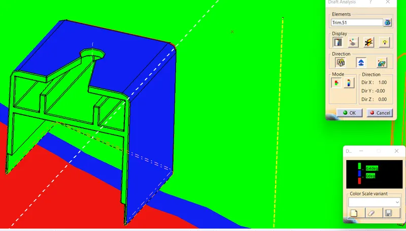
This draft analysis is done with the side core axis , as it is shown the inside area in green is given 0.5 degree draft angle and it is suitable for manufacturing.
CREATION OF FLANGE
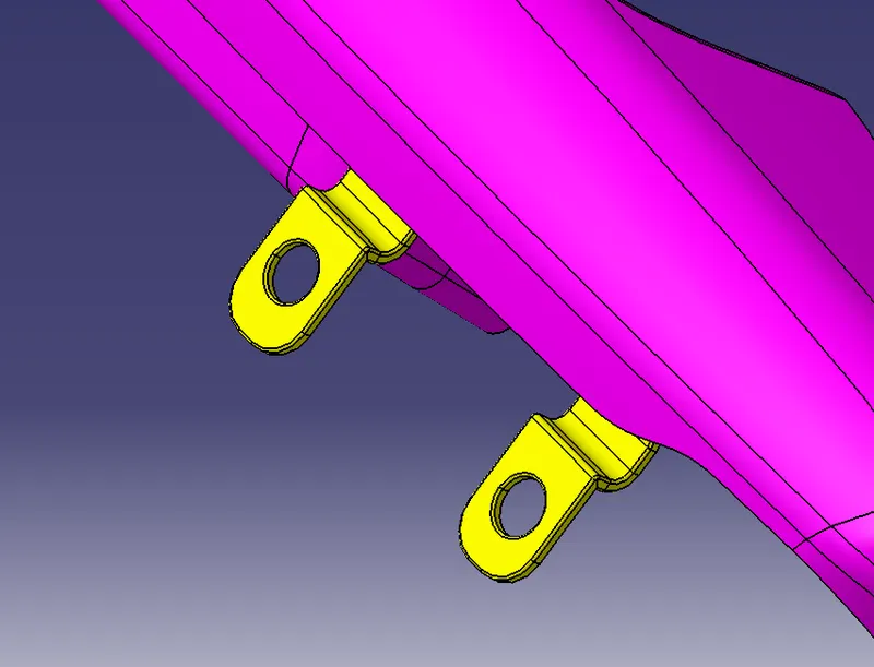
Flanges are created by extracting a boundary making a point on the boundary and then creating a plane there in which we later sketch a shape which is extruded, thickened and holes are created by either hole function or by extruding a circle and removing it and neccessary fillets are given and the body is then union trimmed on to the main body keeping required parts, these flanges are translated to multiple area using point to point translation method.
CREATION OF HEATSTAKES
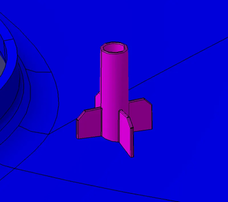
Heat stakes are created by extracting a surface and creating a point and plane on it then sketch of 2 circles of suitable diameter with reference to the flange is sketched and extruded and thickened and ribs are created by creating plane in the bottom of the heat stake and extruding and thickening it and later the unwanted parts are union trimmed with the body and draft angle of 0.5 degree is given to the body and these heatstakes are translated to required areas by point to point translation.
CREATION OF LOCATORS
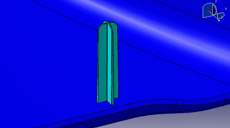
Locators are created by extracting a surface and providing a point and plane on it and a simple sketch of 2 lines are drawn, extrapolated and thickened draft angle of 0.5 degree is given to the body and fillets are given to the required area and the body is union trimmed onto the main body, later the locators are translated to the required area by using point to point translation.
DRAFT ANALYSIS OF HEATSTAKES AND LOCATORS
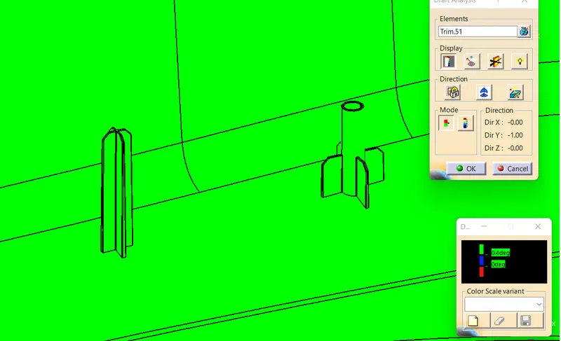
Since the body is given 0.5 degree draft it is shown in green color, which means that it has a optimal draft angle.
FINAL ASSEMBLY OF THE DOOR TRIM PANEL
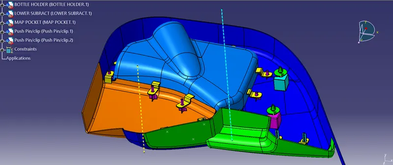
Final assembly is done in the assembly workbench where every part is uploaded and the lower substrate is fixed using the fix constraint and then the flag and heatstakes are joined by coincide function and the pushpins are inserted into the dog house by using coincide and surface contact constraint after doing this all we get a perfectly assembled body.