Week 11 - Final project
AIM: To create a Door interior part from the inputs of class A surface along with master section by following the design rules.
Taken the Thickness of the component to be 2.5 mm from the master section
PROCEDURE FOR DESIGNING DOOR INTERIOR PARTS:
Class A surface: Class A surface is a Styling surface or aesthetic surface get it from the styling team. we will design the plastic component by using the Class A surface as input.
PART 1 Class A surface
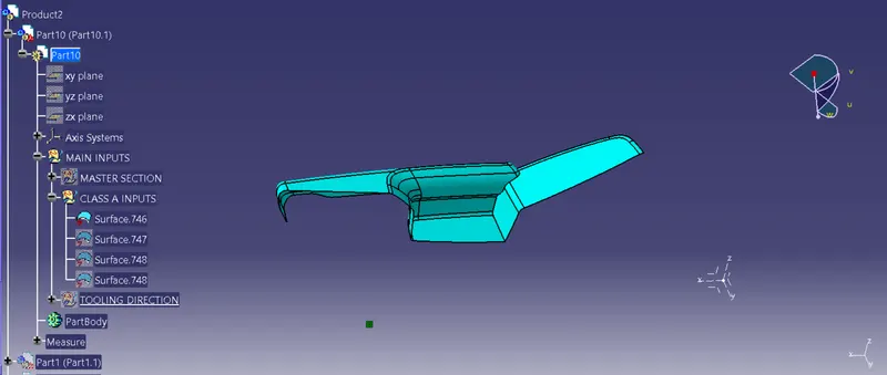
PART 2 Class A surface
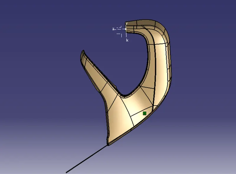
PART 3 Class A surface
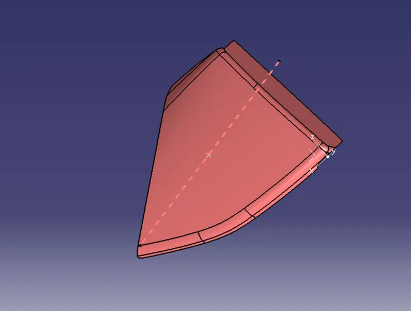
PART 4 Class A surface
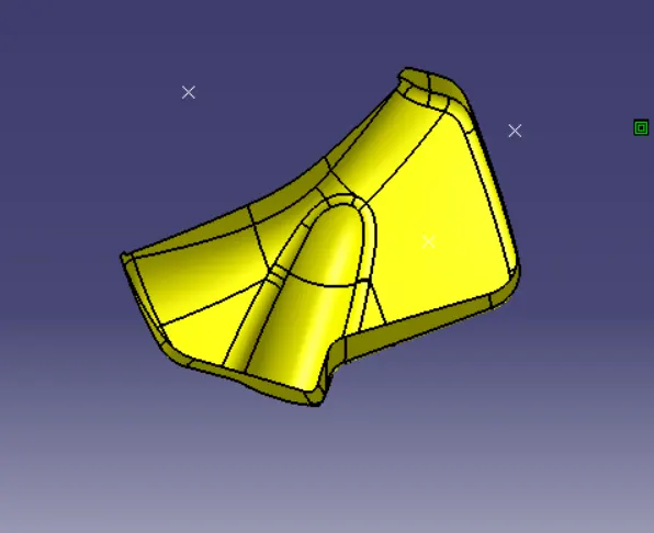
Check all the views of the given class A surface that can help us to understand and get more understanding of the component.
Connectivity of the class A surface that there is no gap between the component, by using joining command or boundary command we can check.
CREATING THE CLASS B SURFACE
Class B surface is to be creating the engineering features and offsetting the surface of class A. Firstly we will extract surfaces by using the extract command and from the class A surface. And if there are any patches we have to make it a smooth surface and finally get the complete boundary.
PART 1
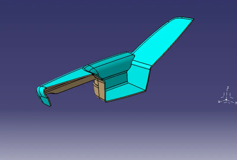
CREATING THE CLASS C SURFACE & FINAL CLOSED BODY
- Class C surface is connected the Class A and Class B, For the class C surface, we need to create the entire boundary of the component by using the boundary command.
- And also creating the best way for the tooling direction to manufacturing easily in an effective way.
- By using the sweep command we can combine them and trim the surfaces so we can get the completed closed surface body and draft angle given as min 3 degrees.
- Before trimming the most important things join them all.
- After the body has to be closed by using the closed surface in part modeling.
PART 1 FINAL CLOSED BODY
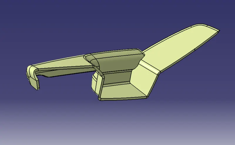
PART 2 FINAL CLOSED BODY
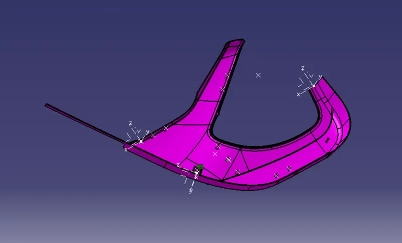
PART 3 FINAL CLOSED BODY
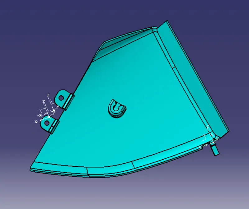
PART 4 FINAL CLOSED BODY
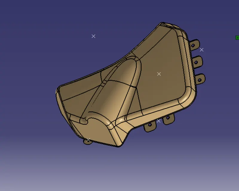
TOOLING DIRECTION & BISECTING
- The tooling direction would be at the axis at that direction it is very easy to manufacture and all the and all faces and the entire surface are to be covered in that direction without adding any other equipment.
- Bisecting, the articular surface is a tool or not we intersect the surface with the respective plane and get a sketch which consists of two lines, and with the help of bisecting line option, we bisect the line which creates a line at the midpoint of the two lines.
- Likewise, we create a tooling clearing axis for x and y which will be used to create the main tooling axis using the bisecting line option in the line command.
PART 1 - TOOLING DIRECTION & BISECTING
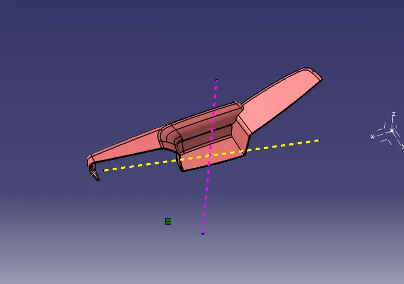
PART 2 - TOOLING DIRECTION & BISECTING
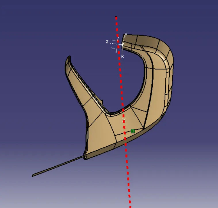
PART 3 - TOOLING DIRECTION & BISECTING
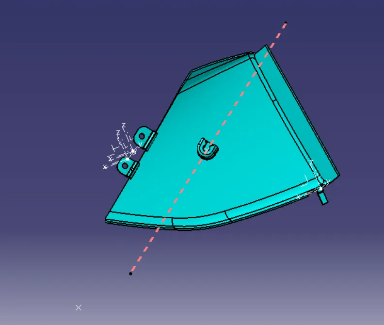
PART 4 - TOOLING DIRECTION & BISECTING
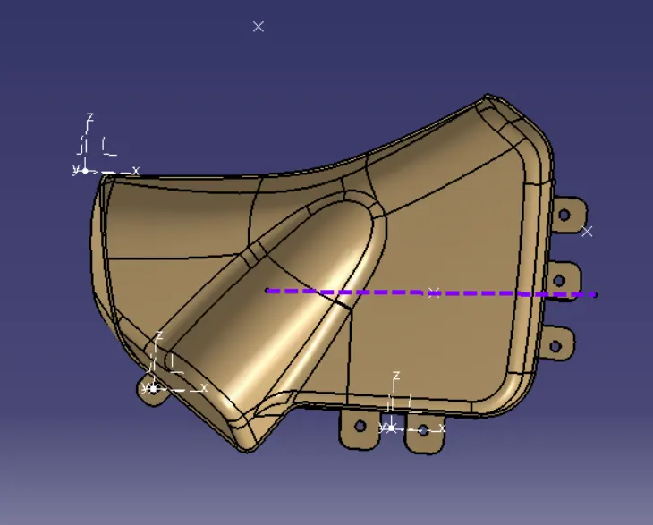
DESIGNING OF THE DOG HOUSE & HEAT STAKE
The dog house is an engineering feature used in the plastic trim design. Dog houses are used as supporting features. Sometimes other engineering features like snaps; locators, etc. are mounded on them to increase their strength. The dog house is mostly used in automotive plastic and its main purpose is to help to avoid sink marks and saver of wall thickness
There are many design factors considered in to design of a dog house:
Doghouse wall thickness at the intersection of the part wall ( C ) should be 40% or less than the main wall stock ( T ).
The height of ( B ) should be between 3.0 – 6.0 mm
Extract the base of Class A Surface and offset it with a part thickness of 2.5 mm.
Draw a sketch of the open rectangle and extrude the rectangle at some height of 30 mm.
Close the upper surface face by offsetting the below-extracted surface and then after trimmed it.
applying part thickness as 2 mm.
Give the draft to the inside surface of 0.5 degrees.
Now to create the C and B sections as shown in the design rules, offset the base surface between 3 to 6 mm.
DOG HOUSE
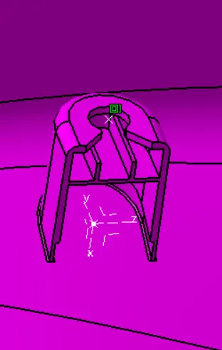
HEAT STAKE
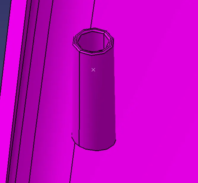
FINAL COMPONENT
PART 1
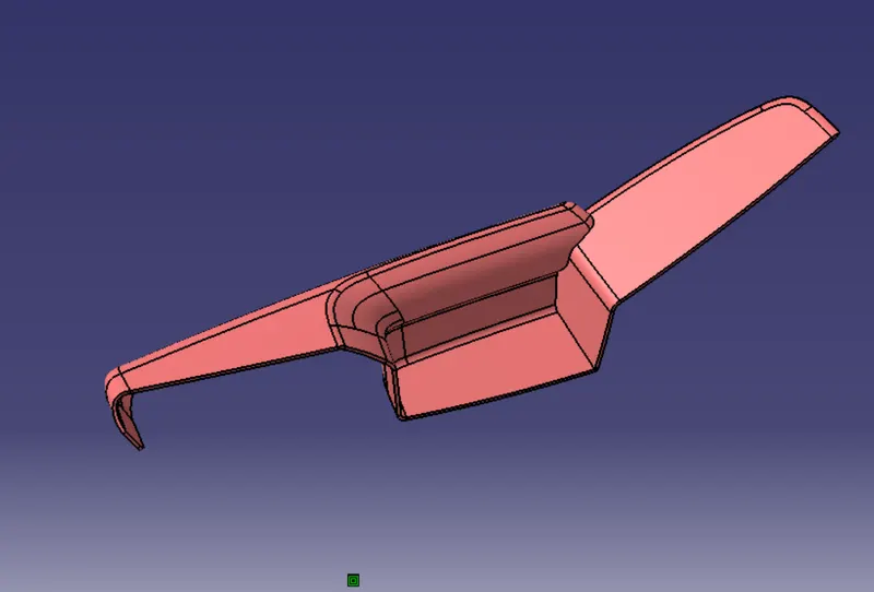
PART 2
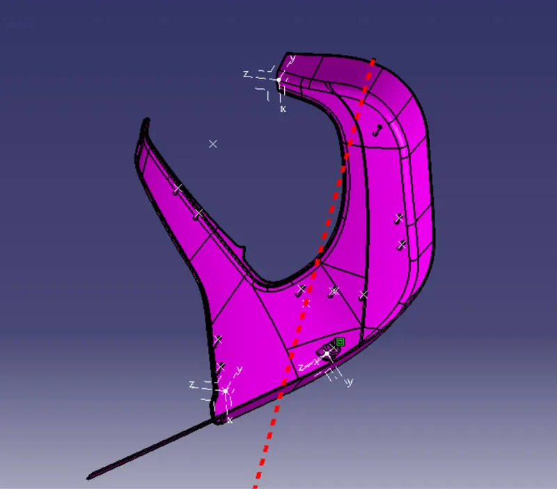
PART 3
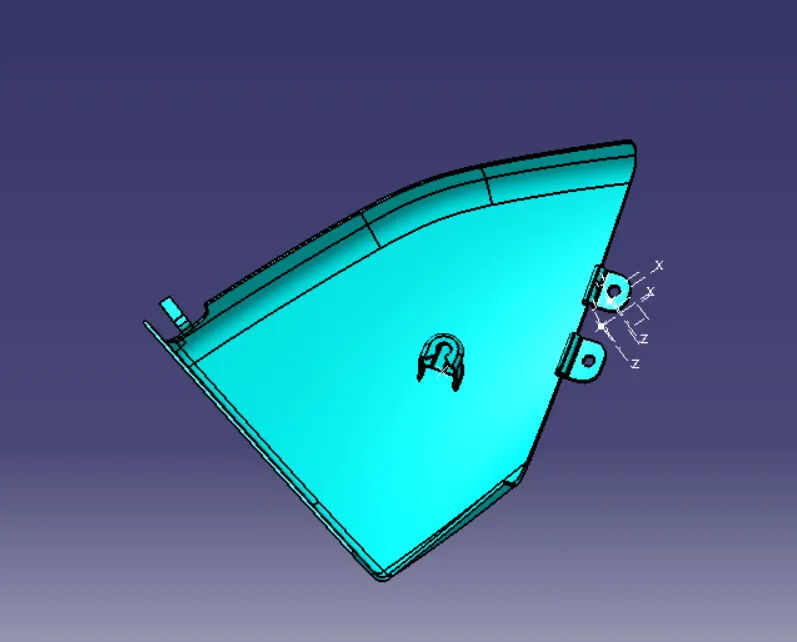
PART 4
VARIOUS ORIENTATIONS OF THE FINAL COMPONENT
PART 1
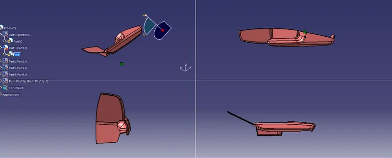
PART 2
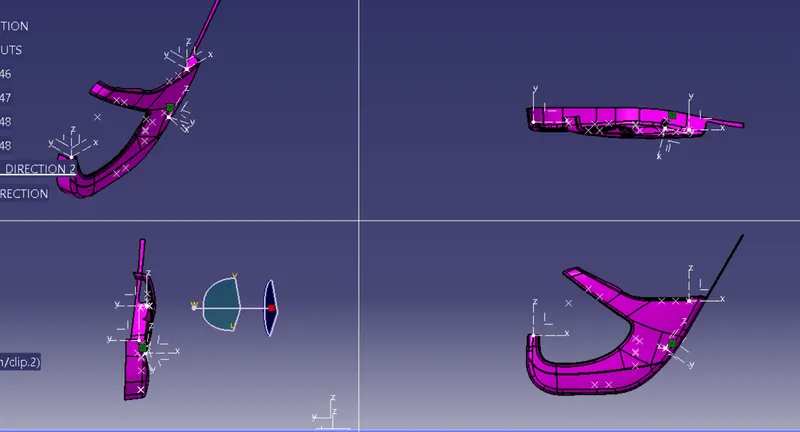
PART 3
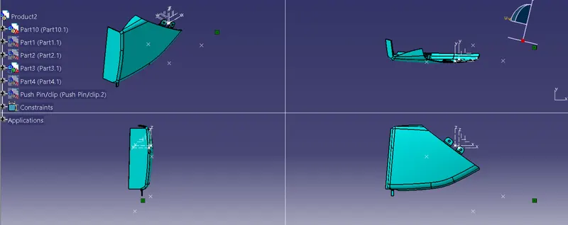
PART 4
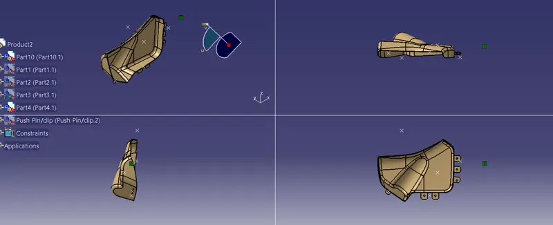
DRAFT ANALYSIS
PART - 1 Draft Analysis for the Final Plastic body:
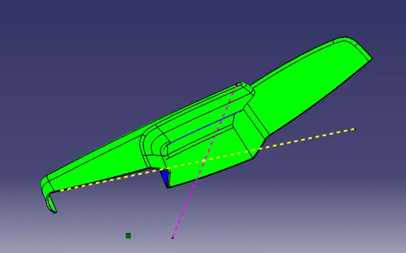
PART - 2 Draft Analysis for the Final Plastic body:
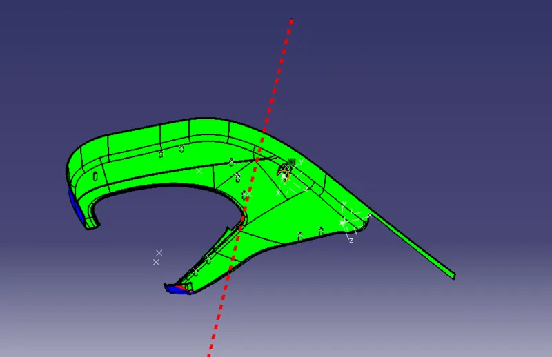
PART - 3 Draft Analysis for the Final Plastic body:
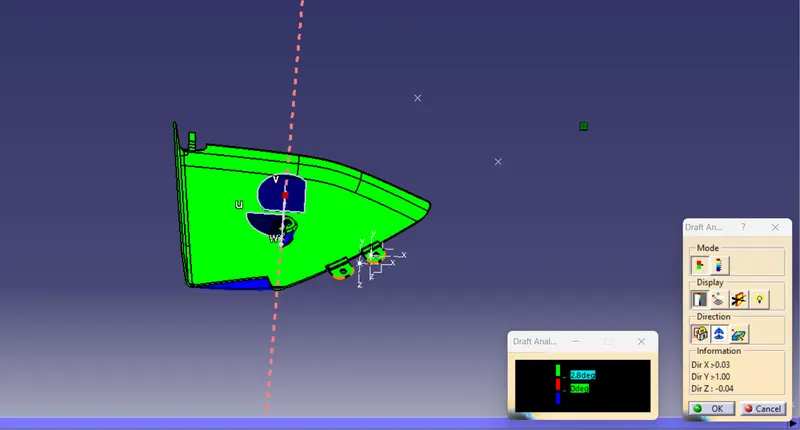
PART - 4 Draft Analysis for the Final Plastic body:
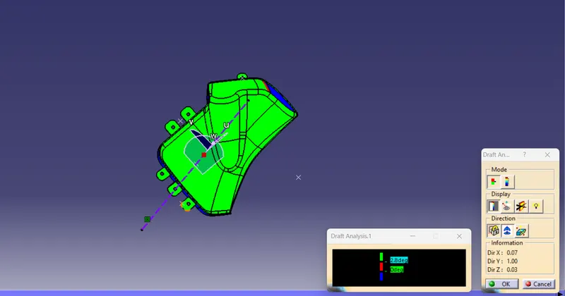
FINAL CLASS A SURFACE ASSEMBLY
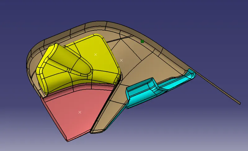
FINAL CLOSED BODY ASSEMBLY
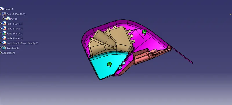
CONCLUSION: Finally created a Door interior part from the inputs of class A surface along with master section by followed the design rules.