Week 11 - Final project
PROJECT REPORT
ON
DESIGN AND DEVLOPMENT OF CAR INTERIOR DOOR TRIM
1⦁ INTRODUCTION
Interior trims: As we know there are many parts in the car. In a car trims are all aesthetic parts that do not add functionality to the vehicle which enhancing the aesthetic and cool factor. They are dividing into two parts •Interior trims: for instance- dashboard, door panel etc. •Exterior trims: It can make the car more beautiful and fashion able and meet about aesthetic and individual need. For instance- bumper,
headlight, wheel wells etc.
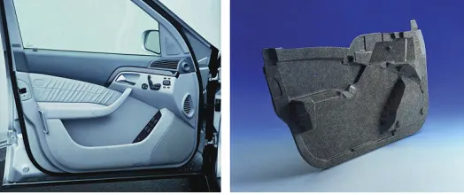
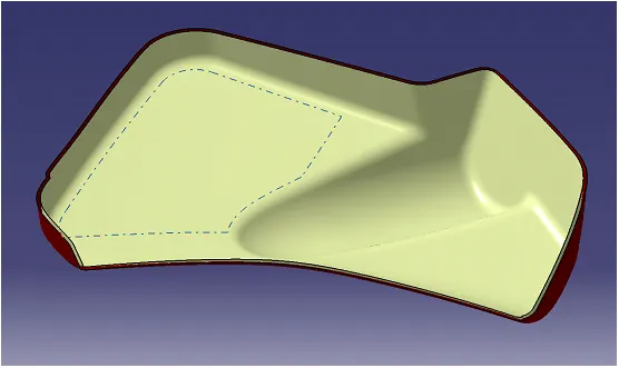
Fig.1 Interior door panel
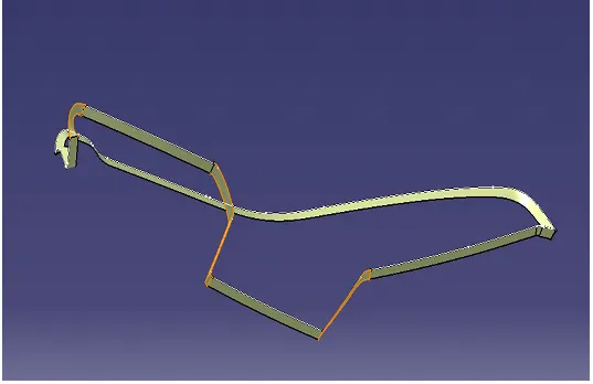
Master section: Master sections are the guides for design requirements which decide the component packaging after technical (Styling, Concept or Class-A) surfaces.
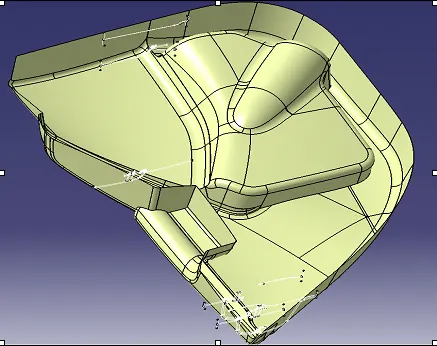
Fig. 2 Mater sections
Class A surface: Class A surfaces can be defined as any surface, that has styling intent, that is either seen, touched, or both. In automotive design application Class A surfaces are created on all visible exterior surfaces (ex; body panels, bumper, grill, lights etc.) and all visible interior surfaces (ex: Dashboard, seats, door pads) .

Product life cycle:
The 10 stages of Product Life Cycle in Automotive industry are
1. Concept Sketching
2. Styling Class -A
3. Feasibility Check
4. Concept Validation
5. New Product Design
6. Development Stage
7. Prototype Build
8. Design Validation
9. Pilot Production
10. Mass Production
2⦁ Aim:
Creation of CAD model considering following inputs as like in OEM and tier1 companies
a) Class A surface
b) Nominal thickness: Refer master sections
c) Attachment strategy:
3⦁ Abstract
This Project explain in brief regarding the Design life cycle followed in automotive industry by working on Practical Model car interior door trim which is a Car interior trim Part. In this Report we have explain about the steps followed to create a solid body of the pillar Cover taking Class A Surface as Input and Creating a Tooling axis and B surface with respect to the Class A Surface and Creation of Class C Surface and also the Draft Analysis. The attachment features also designed and reported as per given master section considering all the design rules for the creation of ribs and doghouse.
4. Problem statement
⦁ Find a attachment strategy for the door panel complete work.
⦁ Use Push pin with Dog house for Lower substrate – Door panel attachment
⦁ Use heat stakes for part to part attachment
5. Objectives
⦁ Create thickened part using master section for reference
⦁ Create the mounting features as per design guidelines in the industry and with master sections
⦁ Apply material details:
⦁ Draft analysis & Tooling analysis
⦁ Creation of parting lines and check tooling feasibility
6. Procedure
Design of interior door trim
In this project consider mainly three major parts of door interior.
⦁ Lower substrate
⦁ Arm rest
⦁ Map pocket
1) Lower substrate
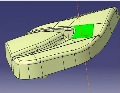
⦁ Creation of tooling axis
⦁ Tooling axis is the direction in which the mold or core and cavity opens
⦁ We should find best possible tooling direction in which all draft angle is with respect to it. So that component can be easily ejected from the mold’s
⦁ To create tooling axis first extracted class A surface and took point on it. Drew line in the vertical direction.
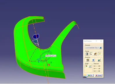
⦁ Draft analysis of class A was done with respects to tooling axis
⦁ Creation of B surface
.
⦁ To create B surface gave offset of 2.5mm to class A surface and where patches was appeared due to offsetting there need to be work on it.
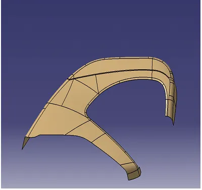
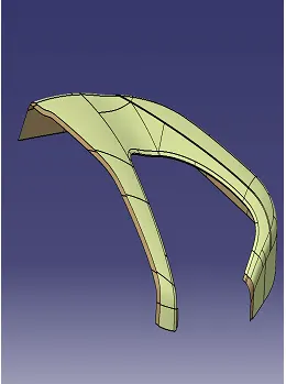
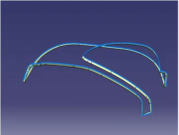
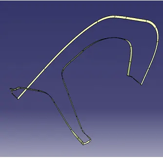
⦁ Creation of C surface
⦁ To create C surface multiple extracted boundary of class A Surface and swept it in outward side with respect to tooling direction
⦁ If any gaps are appeared it should be resolve locally.
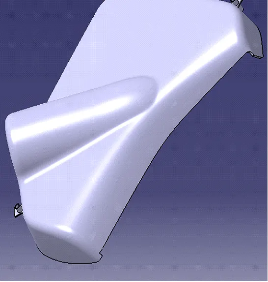
⦁ Final plastic component
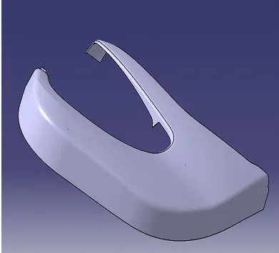
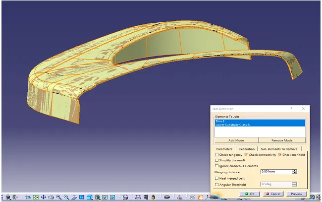
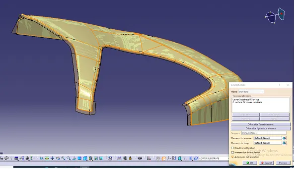
⦁ To get final component C surface was trimmed with B surface
⦁ Further joined that trim with class A surface.
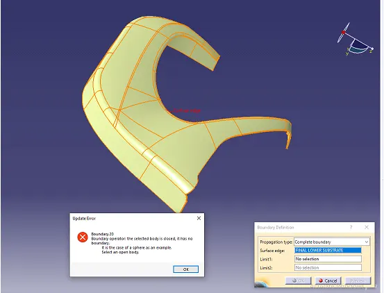
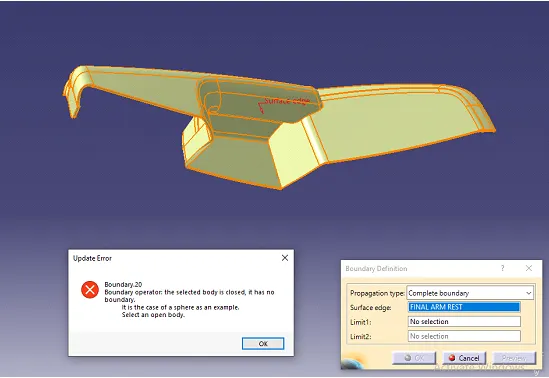
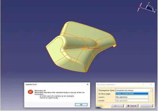
⦁ Checked boundary and it should be shows no boundary and body is close because it ensured there is no openings and made solid plastic component
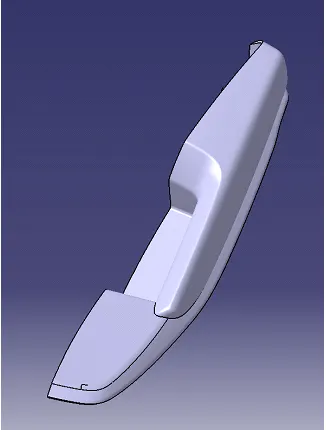
2) Arm rest
⦁ Creation of tooling and lifter axis
⦁ For arm rest lifter (sliding) axis is provided to aid the main tooling axis because main tooling axis cannot cover all the areas of the arm rest
⦁ To create both tooling and lifter (sliding) axis just extracted base surface of arm rest and created two lines in vertical and horizontal direction through point over base surface
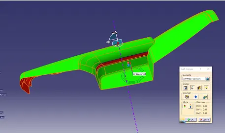
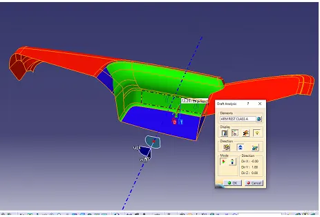
⦁ Draft analysis of class A surface was done with respect to both tooling and sliding axis
⦁ Creation of B surface.
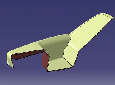
⦁ A surface was offset with 2.5mm. if any patches was appeared there need to be resolved it.
⦁ Creation of C surface
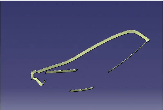
⦁ Took boundary of class A surface and swept it with pulling direction as tooling axis.
⦁ Patches was appeared and it was resolved by created multi section solid.
⦁ This multi sections was joined with swept surface.
⦁ Final component
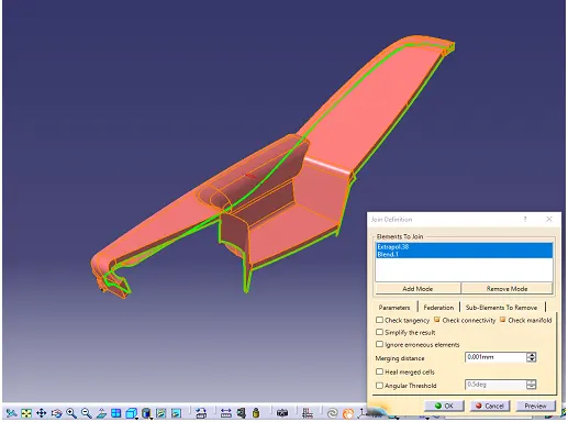
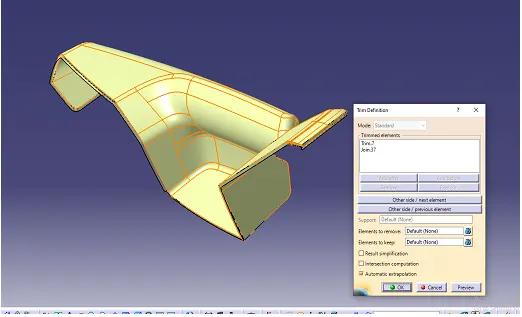
⦁ C surface was trimmed with B surface and joined with Class A surface
⦁ Checked boundary and it should be shows no boundary and body is close because it ensured there is no openings and made solid plastic component
3. Map pocket
⦁ Tooling axis
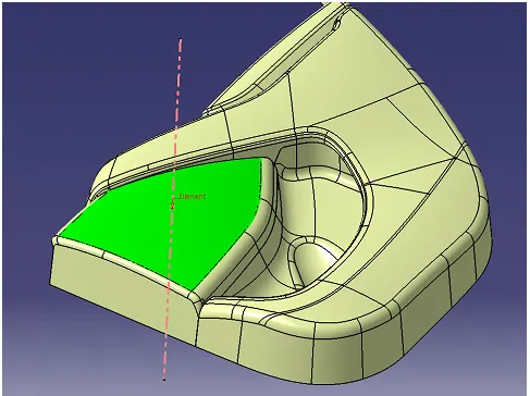
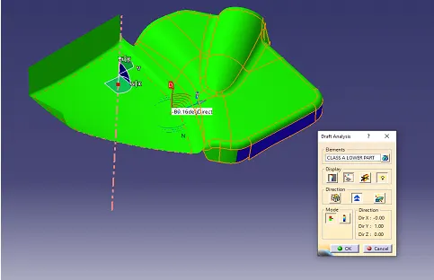
⦁ Similarly here also created line in vertical direction through point over surface which was extracted.
⦁ Draft analysis also was done through this tooling axis
⦁ Creation of B surface
⦁ Class A surface was offset 2.5mm and if any patches is found it should be resolved
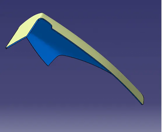
Upper map pocket Lower map pocket
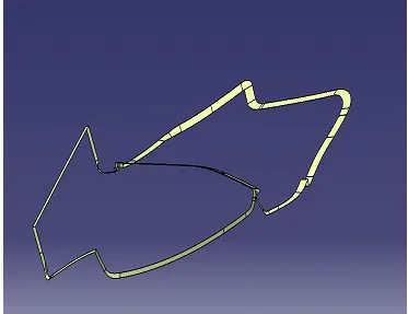
⦁ Creation of C surface
⦁ Class A surface was swept with its boundary in tooling direction.
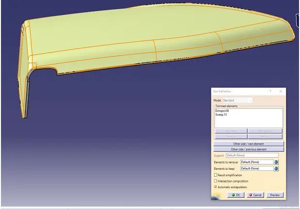
⦁ Final component
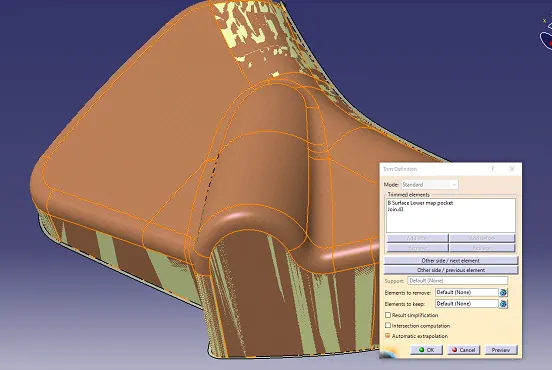
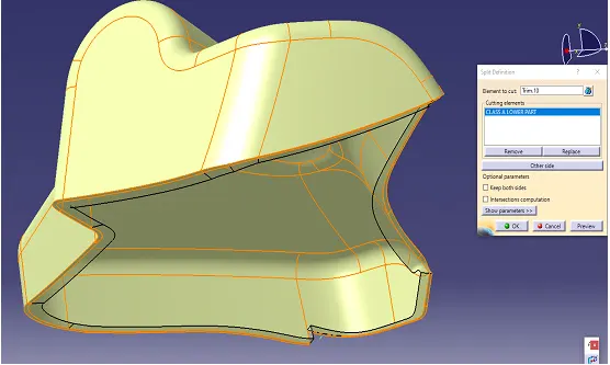
⦁ B surface was trimmed with C surface and further joined with A surface
⦁ If any patches appeared it should be resolved.
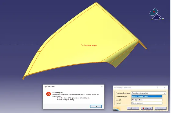
⦁ Checked boundary to ensure no gaps in surface.
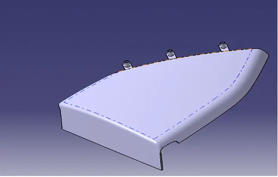
Upper part of map pocket
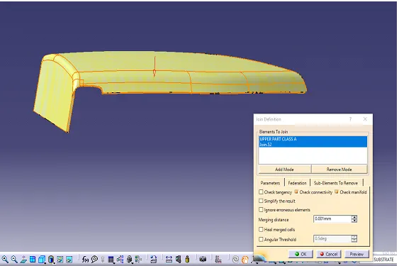
Lower part of map pocket
⦁ Creation of B side features
⦁ Flanges
⦁ Flanges are used to connecting components
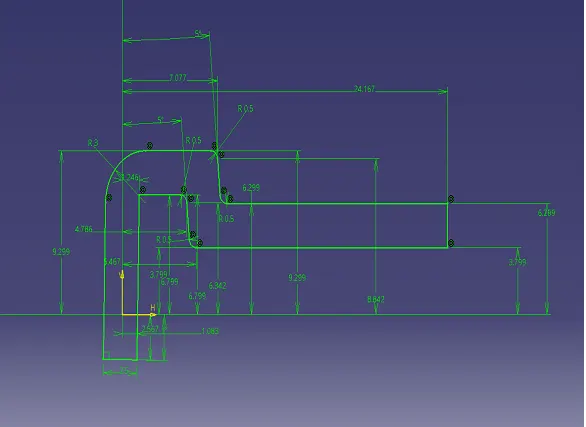
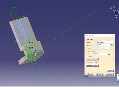
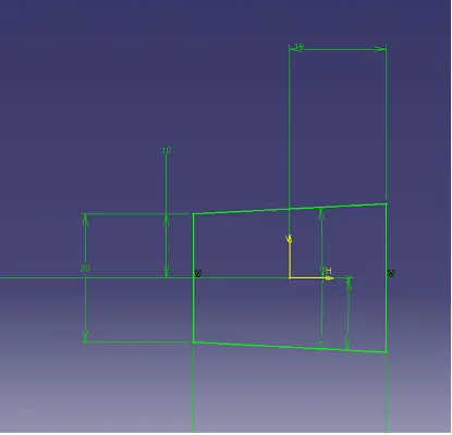
⦁ Here we created flanges using master section given
⦁ Drew sketch for flange and took measurement from given master section
⦁ Draft analysis of flanges was done
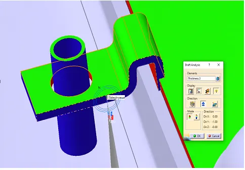
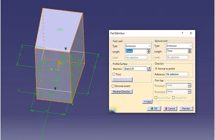
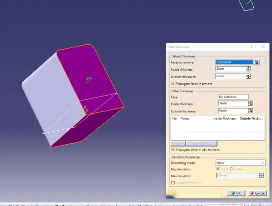
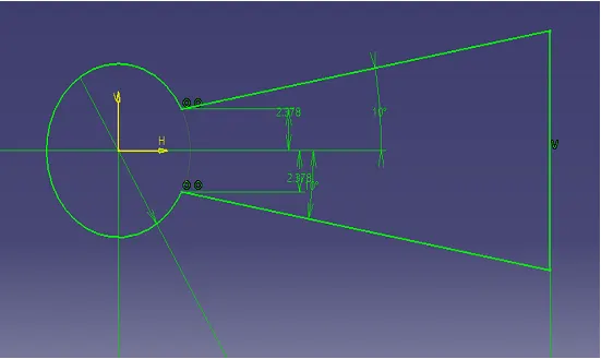
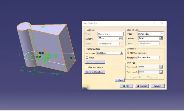
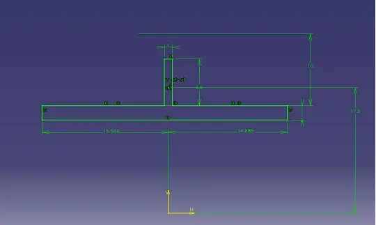
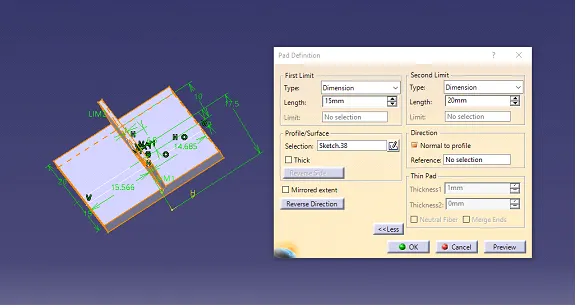
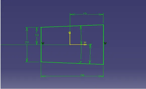
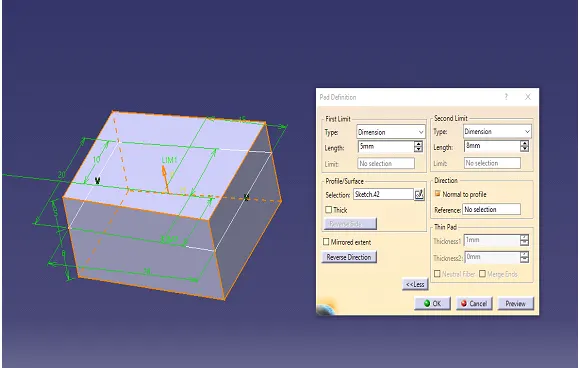
⦁ Dog house with push clips
⦁ Design rules for dog house
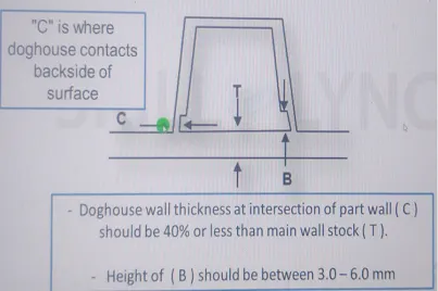
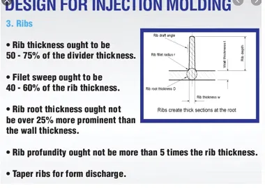
⦁ Design rule for ribs in dog house
Main dog house body
Upper cut on dog house
Ribs inside dog house
Undercut in dog house
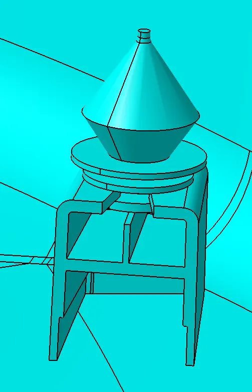
⦁ Draft analysis of dog house was done in both tooling and sliding axis
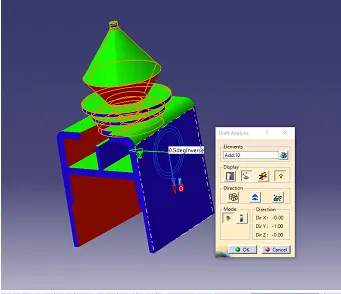
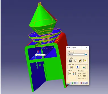
Draft analysis with tooling direction Draft analysis with sliding axis
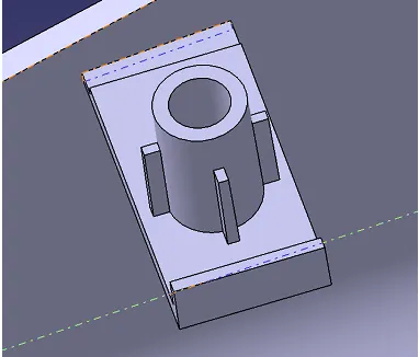
⦁ Screw boss
⦁ General Guidelines for Bosses:
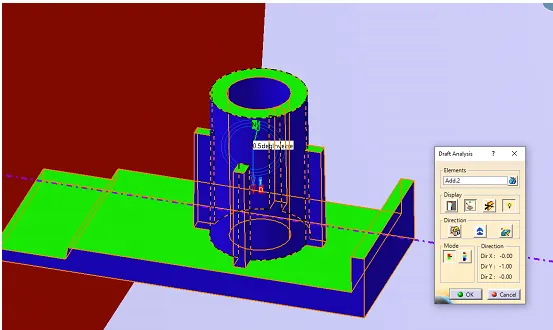
⦁ Draft - 0.5 degrees on walls of boss
⦁ Thickness - Typically 40%* of the nominal wall at the base.
⦁ Height to Diameter Ratio - 3:1
⦁ Radii - 0.25mm maximum radii.
Flange of screw boss
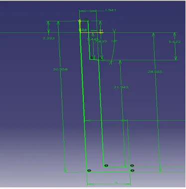
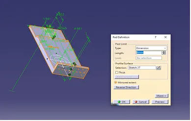
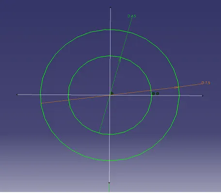
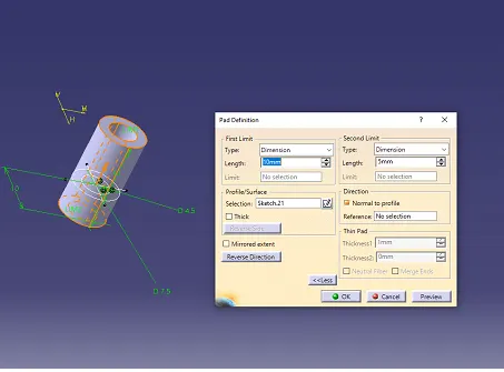
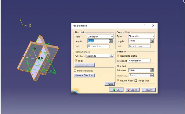
cylinder and ribs
⦁ Draft analysis of screw boss was done
⦁ Heat stakes
⦁ Heat stakes are used to join two or more parts out of which one is made of plastic
⦁ Similar and dissimilar materials may be joined: metal to metal, plastic to plastic, metal to plastic
⦁ Accurate control operating within a small process window
⦁ Local heating resulting in no damage to surrounding materials
⦁ Processing of glass-filled materials
⦁ No mechanical vibration
⦁ Many heat-stake shapes possible through custom designed tools
Clearance
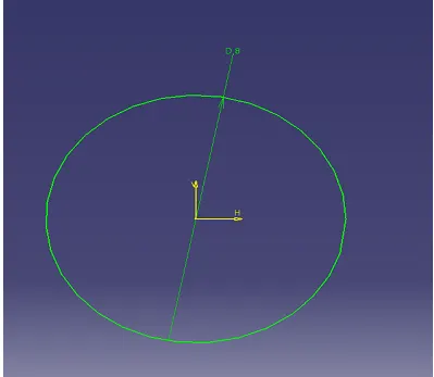
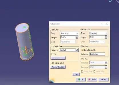
Heat stakes
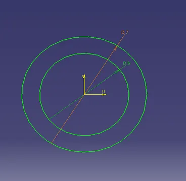
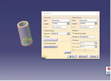
⦁ Draft analysis of heat stakes was done.
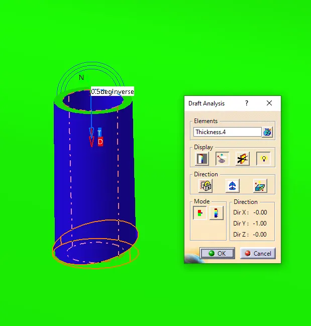
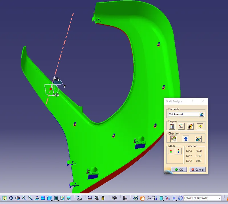
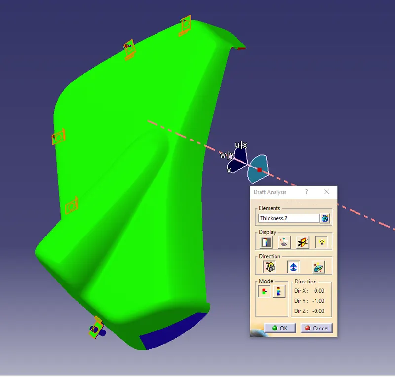
⦁ Draft analysis of final components
Lower substrate main body
Arm rest main body
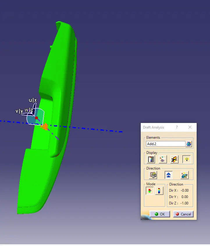
Upper map pocket
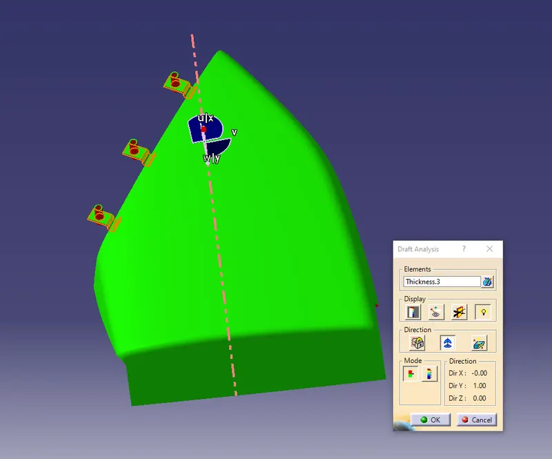
Lower map pocket
7⦁ Final door trim with attachment
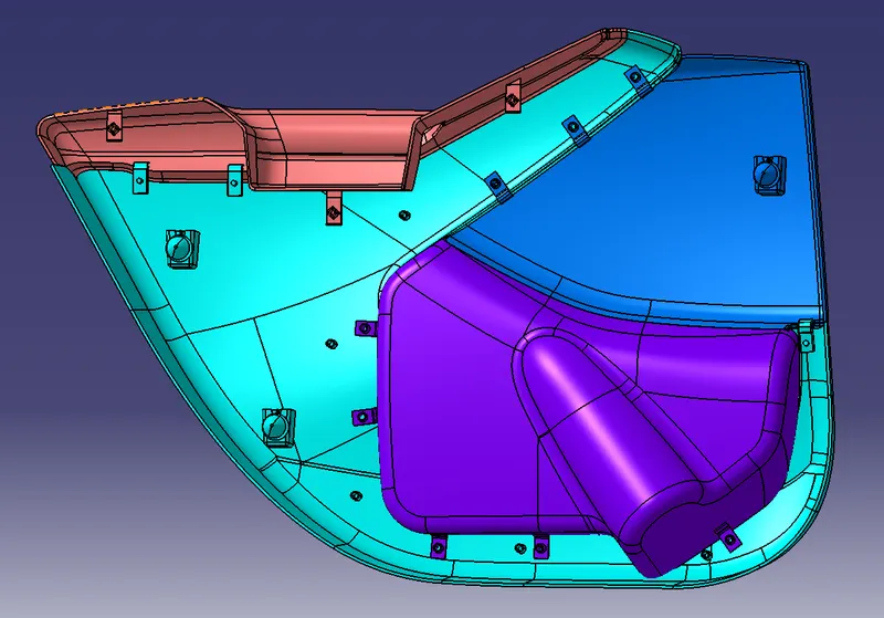
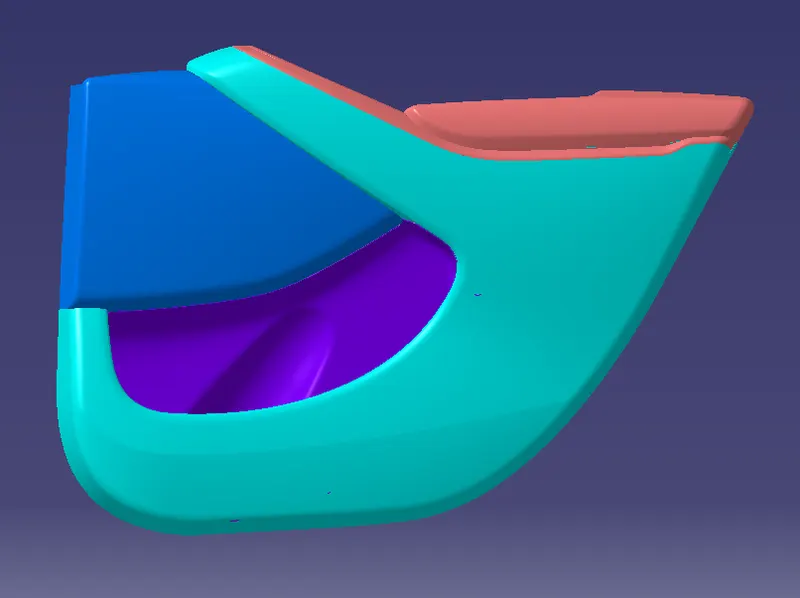
8⦁ Aesthetic side of door trim
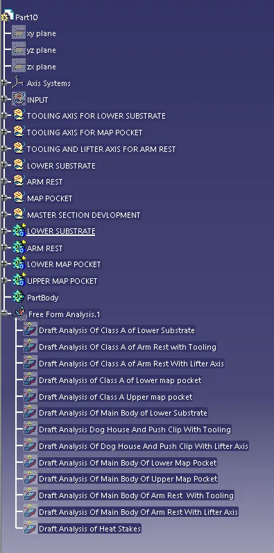
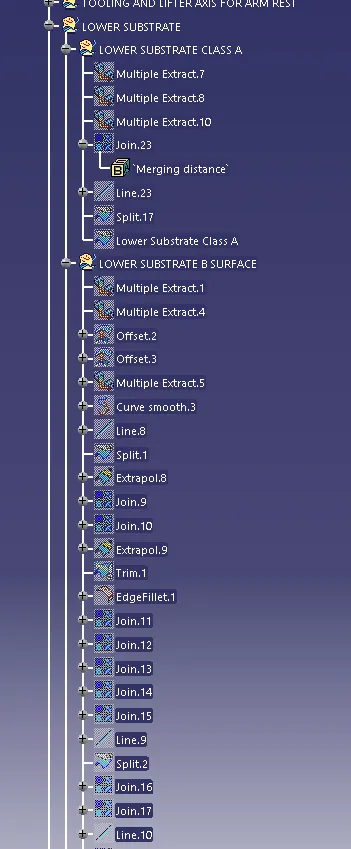
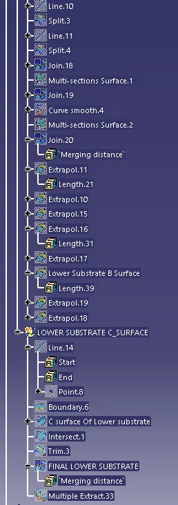
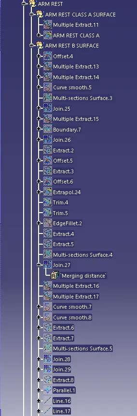
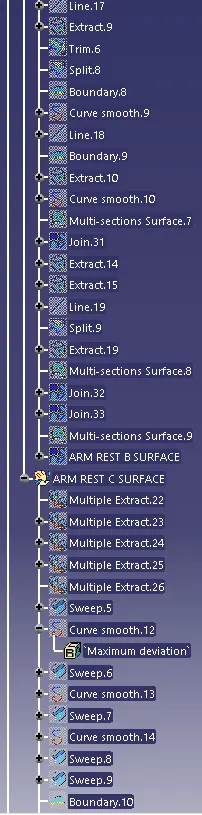
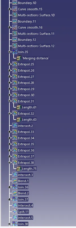
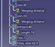
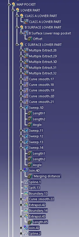
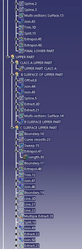
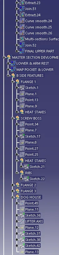
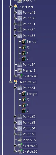
9. Operations Tree
10. Conclusion
⦁ From given inputs like master sections and class A surface car interior door trim is designed
⦁ Creation of B and C surface is done using class A surface
⦁ By considering all design rules for creation of engineering features (b side features) is done with reference of gien master sections
⦁ For easily ejection of component given draft with 3 degree to components and 0.5 degree to attchments