Week 11 - Final project
AIM:
Development of a Door Trim panel CAD model considering given inputs as like in OEM and tier1 companies
standards.
OBJECTIVES:
- Create thickened part using master section for reference
- Create the mounting features as per design guidelines in the industry and with master sections
- Apply material details :
- Draft analysis & Tooling analysis
- Creation of parting lines and check tooling feasibility
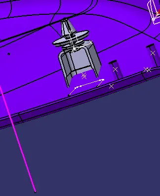
- Use Push pin with Dog house for Lower substrate – Door panel attachment
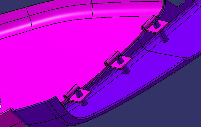
- Use heat stakes for part to part attachment
PROCEDURE:
The steps that I followed for this project is mentioned below:
- Extracting the class A surface from the input
- Draft Analysis of class A
- Creation of Class B and Class C surface from Class A
- Created the solid body and performed the draft analysis on the solid body
- Created the Engineering features
- Draft analysis of the component with Engineering features.
GIVEN INPUT:
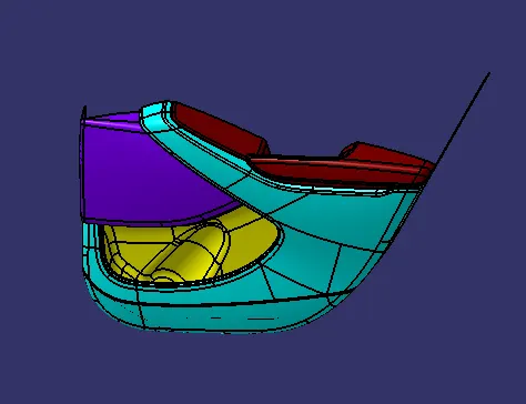
The Class A surfaces of Car door Plastic components from the Styling team used are,
- Lower substrate.
- Arm rest.
- Mat Pocket
Firstly i have considered lower substrate,
LOWER SUBSTRATE:
CLASS A SURFACE OF LOWER SUBSTRATE:
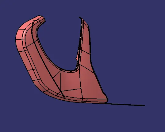
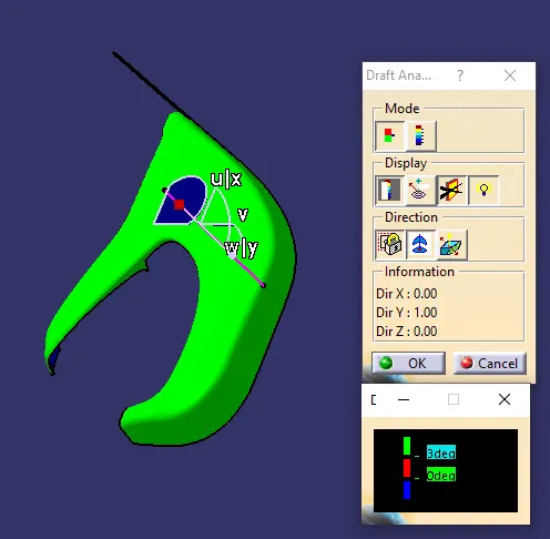
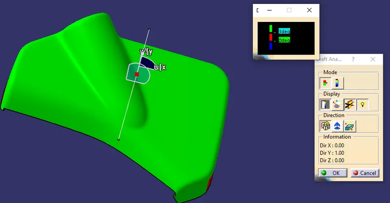
Now I have to perform the draft analysis on the class A surface. For the draft analysis, I need a tooling axis for this lower substrate.
TOOLING AXIS OF LOWER SUBSTRATE:
Observe the defects in the Class A surface the damaged portions need to be repaired by using the required surface workbench commands and by using Boundary command observe the open brackets surface body i.e Class A, if the boundary is defined only at the boundary of the Class A then it is a damage free Surface .
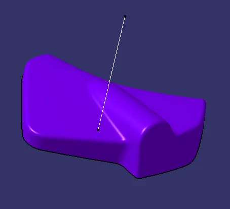
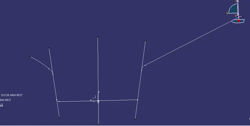
Tooling axis is nothing but the direction in which the core and cavity opens and closes. Design engineer works is to analyse the Class A surface and find out the best possible tooling direction keeping in mind all the draft angle is with respect to the tooling axis so that the component can be easily ejected from the moulds.
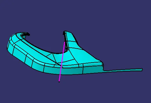
I will start by inserting a geometrical set and naming it as a tooling axis for lower substrate . For creating the tooling axis I will analyze the model and see from which direction I can see the whole model. so here the direction I have chosen for the tooling axis is along y-direction because along y-direction the whole model is visible properly. For creating the tooling axis I will create one point on the lower substrate and from that point, I will create one line along the y-direction and that line will be my tooling axis.
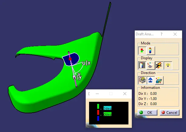
DRAFT ANALYSIS OF LOWER SUBSTRATE CLASS A SURFACE:
Draft
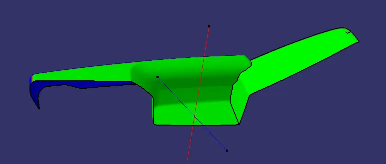
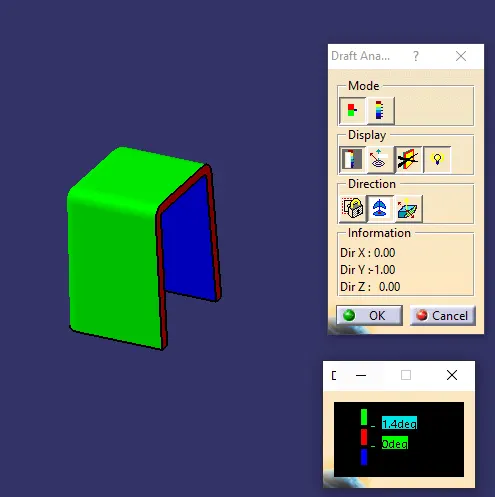
To facilitate easy removal of components from the mold, it is necessary to add a taper all along the surface with reference to the tooling direction. This taper is termed as a draft and its value ranges from 0.5 degrees to 3 degrees, with the latter being the most widely accepted norm.
Draft Analysis
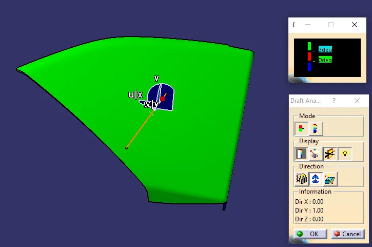
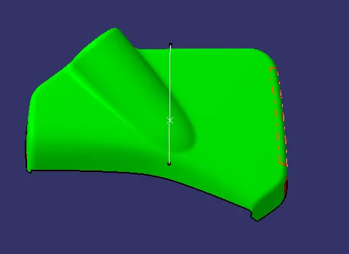
The draft analysis command in CATIA helps to detect whether the drafts provided in the model will facilitate easy removal of the component during manufacture.
This analysis is performed based on colour ranges identifying zones on the analyzed element where the deviation from the draft at any point, corresponds to specified values.
- When the draft angle value of the surface is equal or smaller than a graduated value, the color below the graduated value is applied
- When the draft angle value of the surface is greater than the greatest graduated value, the color above this graduated value is applied
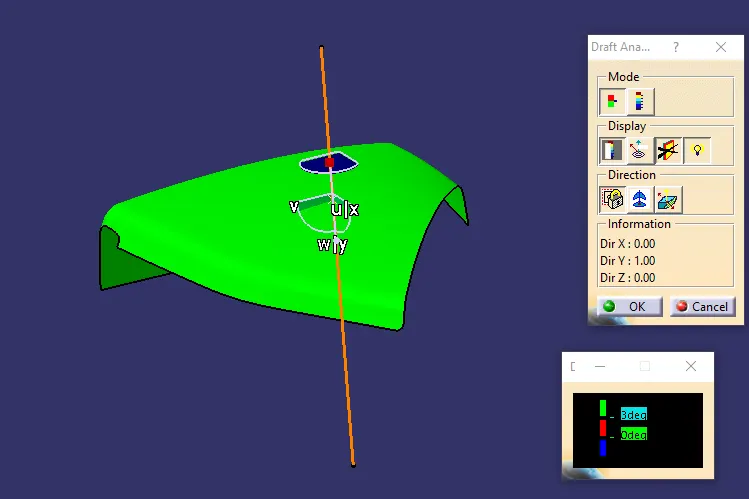
In this project, the required draft for all surfaces were chosen as 3 degrees.
CLASS B SURFACE OF LOWER SUBSTRATE:
It is a surface that gives thickness from a class A surface. All the supporting features of the component will be formed on the B surface only. so we can say that Class B is an engineering surface and Class A is an aesthetic surface.
For creating the class B surface I have offset the Class A surface to 2.5 mm which is the thickness of the part according to the master section that is given as the input.
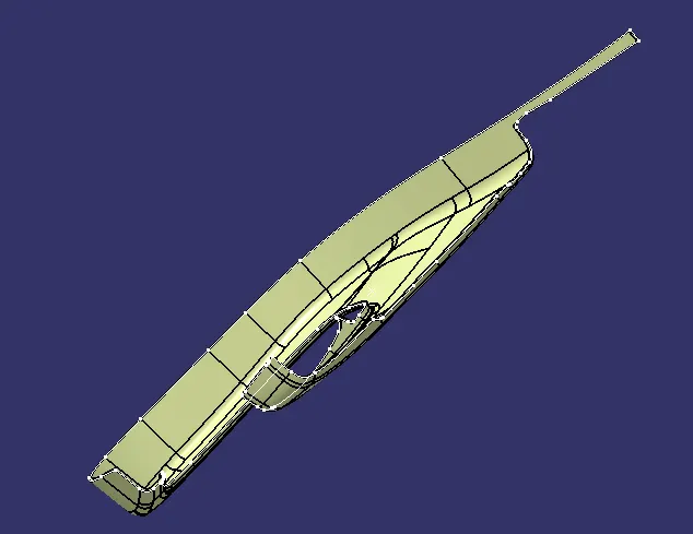
CLASS C SURFACE OF LOWER SUBSTRATE:
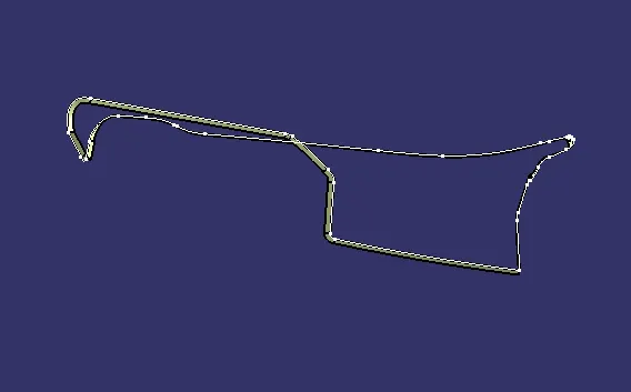
- The C surface forms the connection between the Class-A and B surfaces and is essentially the thickness of the final component
- The C surface was formed using the sweep tool
- For this command, the side flanges and its boundary were extracted from the Class-A Surface and then swept to form the C surface
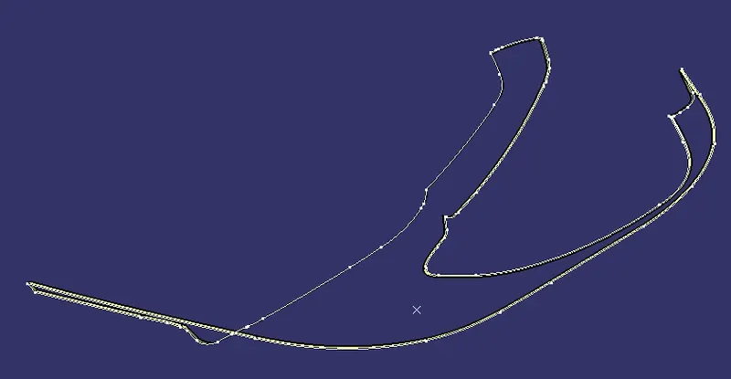
CLASS A+B+C SURFACE OF LOWER SUBSTRATE:
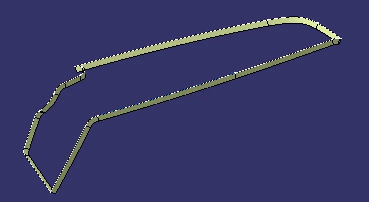
After creating the class C surface I have joined it with the class A surface. Then finally I have trimmed the Join of class A and class C with class B surface to get the required part.
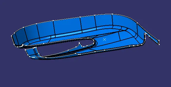
FINAL LOWER SUBSTRATE BODY:
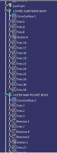
I have made sure that I have a close surface. so for validating that I have to use the boundary option and clicked on the surface I got an error which proves that I have a closed surface. After this, I have created a solid body from this closed surface by using the close surface feature in part design. The solid lower substrate is shown below:
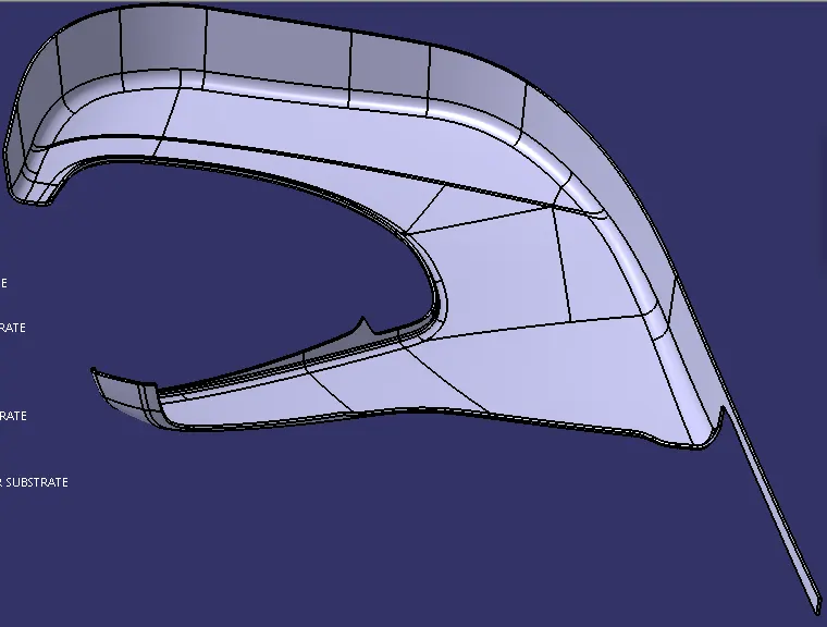
DRAFT ANALYSIS LOWER SUBSTRATE BODY:
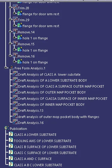
I have performed the draft analysis on the solid part,
Now after creating the lower substrate I have created the map pocket
For the map pocket, I have divided it into two parts one is the inner map pocket and the other is the outer map pocket.
OUTER MAP POCKET:
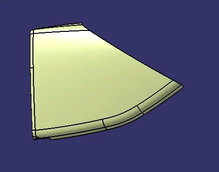
First creating the outer map pocket following the same procedures as I did for the lower substrate. So extracting the outer map pocket surfaces from the input.
EXTRACTED CLASS A SURFACE OF OUTER MAP POCKET:
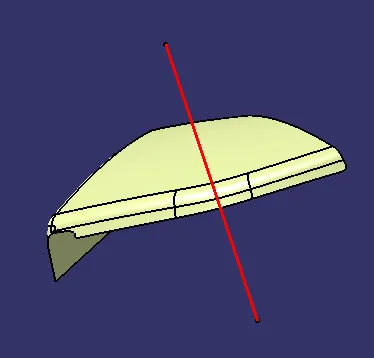
TOOLING AXIS OF OUTER MAP POCKET:
For creating the tooling axis I have created the point on the surface and from that point, I created a line which is the tooling axis for the outer map pocket.
DRAFT ANALYSIS OF OUTER MAP POCKET CLASS A SURFACE:
CLASS B SURFACE OF OUTER MAP POCKET:
Now for the class B surface I have offseten the class A surface to 2.5 mm.
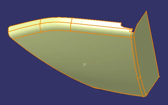
CLASS C SURFACE OF OUTER MAP POCKET:
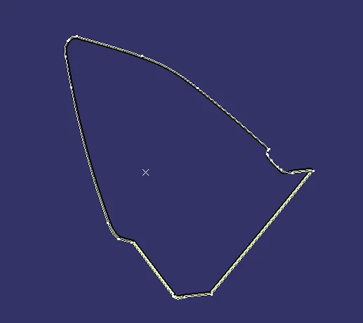
CLASS A+B+C SURFACE OF OUTER MAP POCKET:
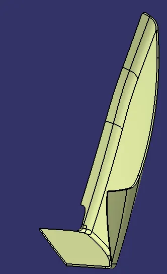
FINAL OUTER MAP POCKET BODY:
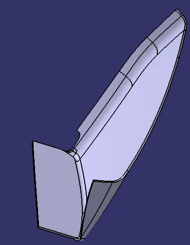
DRAFT ANALYSIS OUTER MAP POCKET BODY:
INNER MAP POCKET:
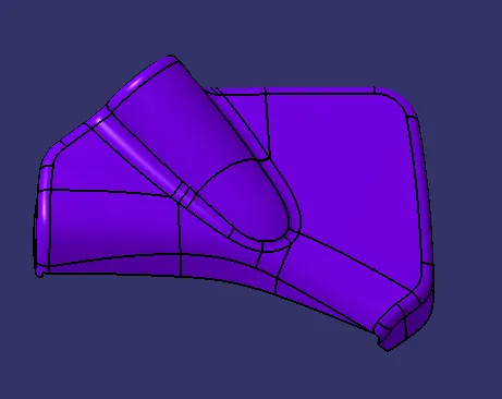
First creating the outer map pocket following the same procedures as I did for the lower substrate. So extracting the outer map pocket surfaces from the input.
EXTRACTED CLASS A SURFACE OF INNER MAP POCKET:
TOOLING AXIS OF INNER MAP POCKET:
For creating the tooling axis I have created the point on the surface and from that point, I created a line which is the tooling axis for the outer map pocket.
DRAFT ANALYSIS OF INNER MAP POCKET CLASS A SURFACE:
CLASS B SURFACE OF INNER MAP POCKET:
Now for the class B surface I have offseten the class A surface to 2.5 mm.
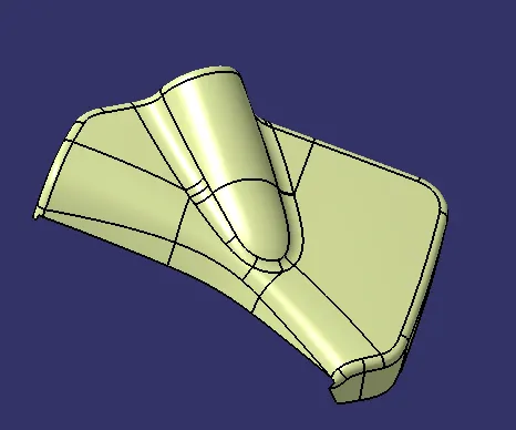
CLASS C SURFACE OF INNER MAP POCKET:
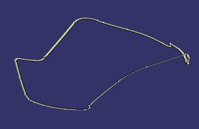
CLASS A+B+C SURFACE OF INNER MAP POCKET:
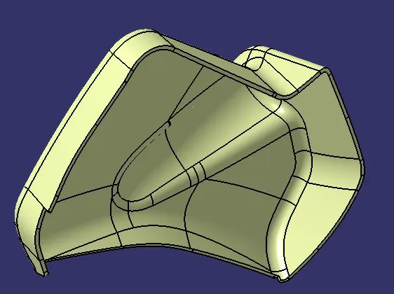
FINAL INNER MAP POCKET BODY:
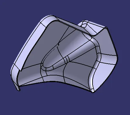
DRAFT ANALYSIS INNER MAP POCKET BODY:
DOOR ARM REST:
A Feature provided on Car door Panel, to support a arm and is made up of Plastic. For creating the Door arm rest following the same procedures as I did in the above. So extracting the outer map pocket surfaces from the input.
EXTRACTED CLASS A SURFACE OF DOOR ARM REST:
The Arm rest portions from the Class A surface is extracted by the extract command
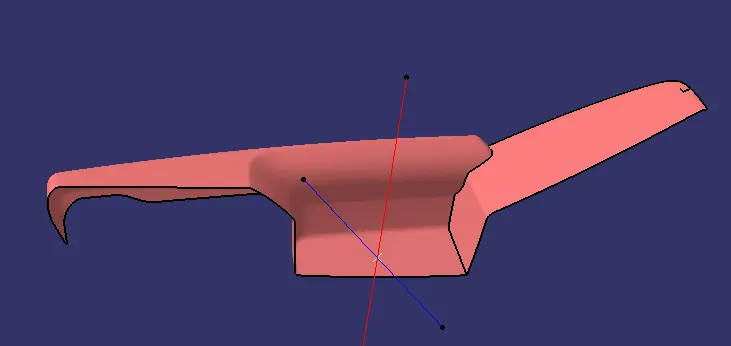
The Arm rest portion is divided into two parts initially as part 1 and Part 2 in order to design the parts in an ease way.
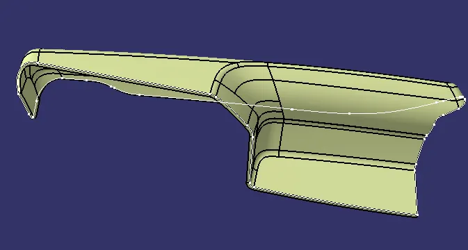
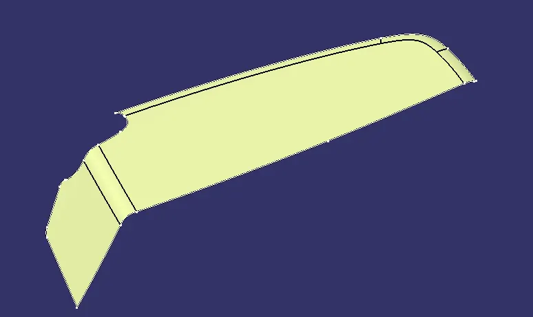
Observe the defects in the Class A surface the damaged portions need to be repaired by using the required surface workbench commands and by using Boundary command observe the open brackets in the Joined surface body
TOOLING AXIS OF DOOR ARM REST:
DRAFT ANALYSIS OF DOOR ARM REST CLASS A SURFACE:
CLASS C SURFACE DOOR ARM REST:
CLASS A+B+C SURFACE OF DOOR ARM REST:
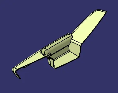
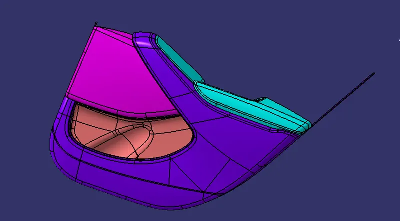
FINAL BODY OF DOOR ARM REST:
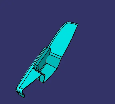
FLANGES:
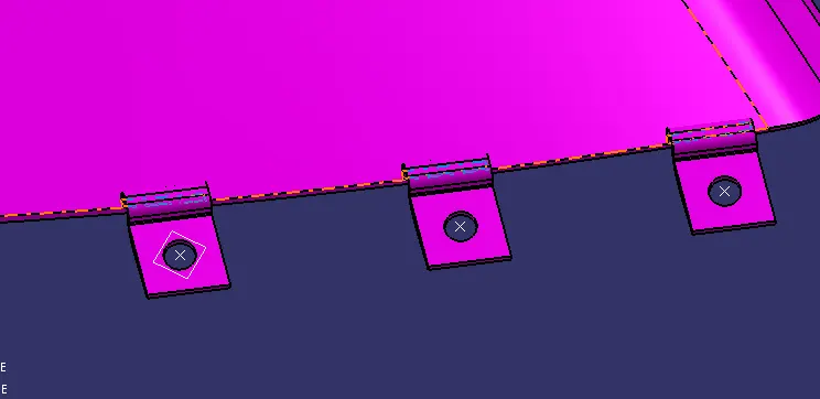
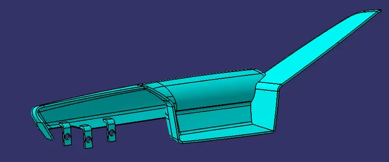
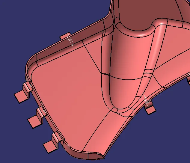
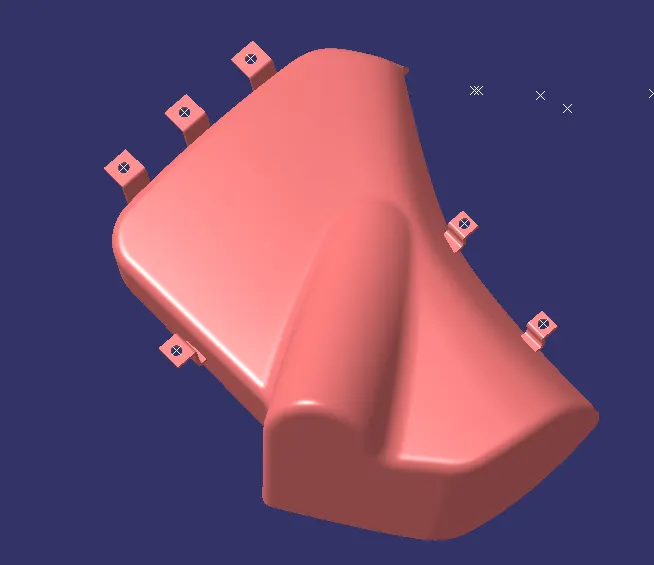
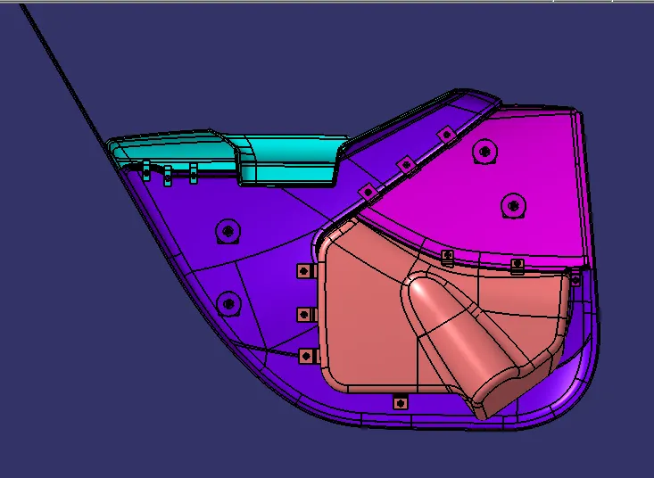
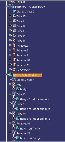
Flanges are the elements that are needed to join different components together. So here I have to make flanges on the door armrest and the map pocket. Following the master section, given as the input basically the measurements and location of the flange. I have created the flanges. First I have created the flange on the outer map pocket. For creating the flanges I have taken extraction of the curve and made a point on that curve then created one plane on that point followed by creating a sketch on that plane taking the point created as the origin.
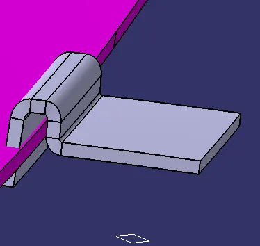
I have copied the flange body and paste it on the main part body using the as result with a link option in paste special.
After pasting I have translated the flange using the point-to-point translation feature Then after the translation, I have used the union trim boolean operation to make one single body.
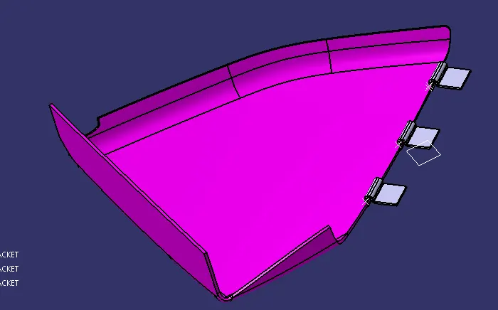
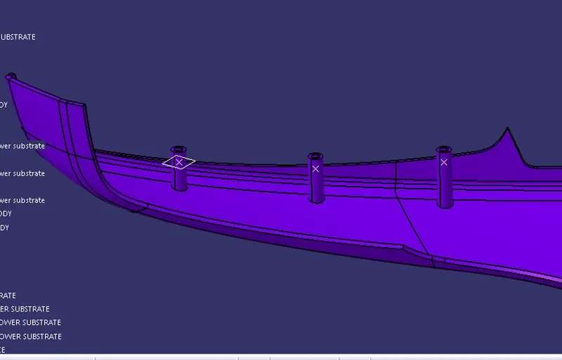
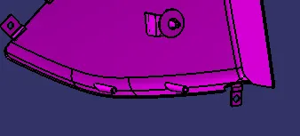
Heat staking:
Heat staking also known as thermoplastic staking is the process of joining two dissimilar materials together. In heat staking, we use local heating and cooling to raise the temperature of plastic components and allow plastic reforming to be carried out. This reforming can be used in a wide variety of applications.
Dog House and push pin:
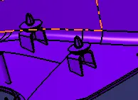
Dog house is an engineering feature used in the plastic trim design. Doghouses are used as supporting features. Sometimes other engineering features like snaps; locators, etc. are mounded on them to increase their strength. Dog houses are subjected to draft analysis to prevent breakage of the component during ejection from the mold cavity. Dog house and other engineering components are built on B-surface.
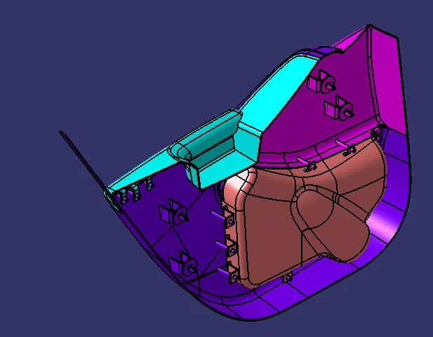
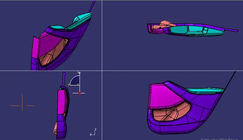
FINAL BODY:
CONCLUSION:
This concludes the creation of the Door Trim Panel along with engineering features using the master section given as the input