Week 11 - Final project
AIM
Development of a door trim panel.
OBJECTIVE
- Creation of CAD model using given class A surface.
- Consider the thickness of the component using master section.
- Find best attachment strategy for the door panel complete work.
- Use push pin with dog house for lower substrate – door panel attachment.
- Use heat stakes for part to part attachment.
INTRODUCTION
DOOR TRIM PANEL :-
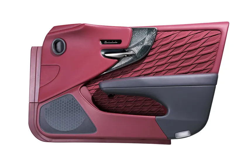
figure 1. door trim panel
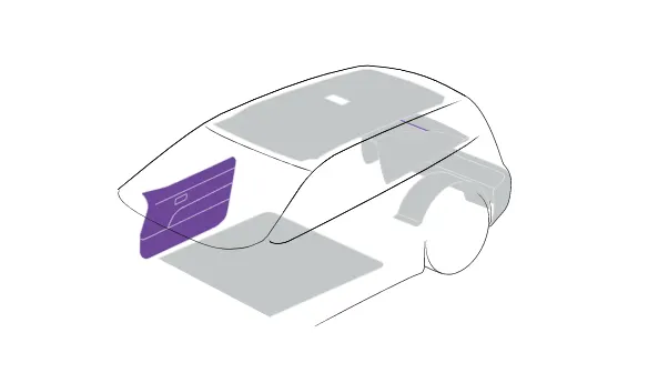
figure 2. the position at which door trim fixed
Next to the dashboard, the door trims are the interior parts that contain the most controls and decorative parts. As such, there is a necessity for balancing gap between parts, as well as an overall sense of unity between the numerous parts. Door trim panel consist of map pocket, bottle holder, lower substrate and arm rest and upper substrate.
Attachment strategy :-
- Here heat stakes is used for the part to part attachment. Heat staking is an assembly process that utilizes controlled melting of thermoplastic materials.
- Here push pin with dog house is used in lower substrate for door panel attachment.
- Here locators, heat stakes, dog house and flanges with holes are provided for best fit and proper attachment strategy as per the guidelines in OEM and tier 1 companies.
MATERIAL SELECTION
- Here the component is door trim, it needs high surface brightness and excellent surface aspect.
- So I choose ABS as material. Because Acrylonitrile Butadiene Styrene provides high rigidity, good impact resistance, good insulating properties, good abrasion and strain resistance and high dimensional stability.
- Especially ABS having good weldability and its really usefull because here I used heat stakes in attachment features. So it will get advantage in plastic welded.
LOCATOR DESIGN :-
- Height of the locators should be 1 mm (or) 2 mm greater than the heat stakes
- Thickness, fillet and draft angle are of same as rib design rules.
- Ideal Chamfer value - 5 mm x 45 degrees
- Ideal length of the locators - 15 mm
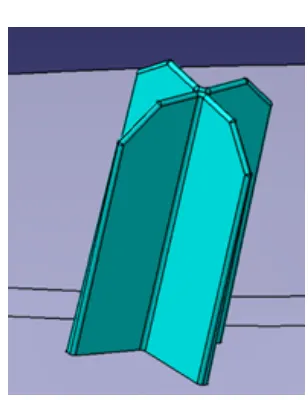
figure 3. locator
HEAT STAKES DESIGN :-
- Counter Part Thickness - Will be given as input
- Component Wall Thickness - Will be given as input
- Length of the Rib - 22 mm
- Height of the Ribs - 3 mm to 6 mm
- Inner Diameter of Heat Stake (d) - 5 mm
- Outer Diameter of Heat Stake (d) - 7 mm
- Minimum clearance between heat stake and counterpart - 0.5 mm
- Height of the Heatstake - Depends on the rib height and counter part thickness
- Minimum fillet of Heat Stakes - 0.25 mm
- Minimum Draft Angle of Heat Stakes - 0.5 degrees
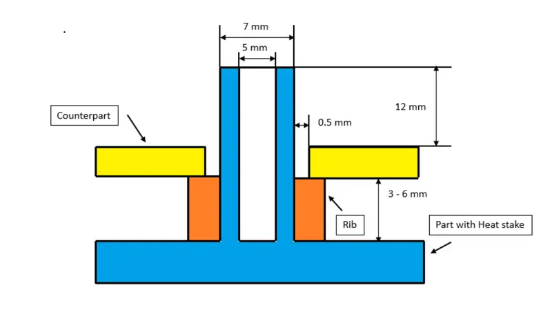
figure 4. heat stakes
Dog house design :-
- Height of the Dog House – 28mm
- Thickness of the Dog House (t) - 2mm
- Coring Height (B) - 6 mm
- Coring Thickness (C) - 40% of Wall Thickness of the component – 0.8mm
- Length and Breadth of the Dog House can be decided upon the application
- Inner Fillet of Dog House (Thickness t) - 0.5 mm
- Outer Fillet of Dog House (Thicknes t) - t + 0.5 mm -2.5mm
- Fillet for the Corting Face - 0.25 mm
- Draft Angle for Dog House- inner - 0.5 degrees
- Draft angle for dog house – outer – 3 degrees – as per the given data.
- Key hole cut-out is made as per the given push pin.
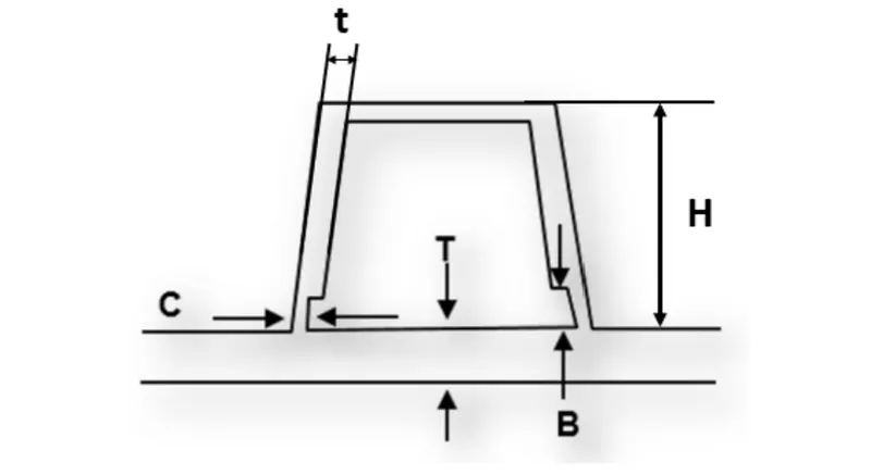
figure 5. dog house
INPUT DATAS
- SURFACES
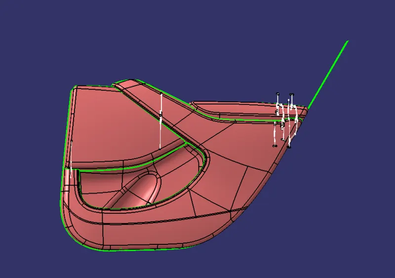
figure 6. given surfaces
- MASTER SECTION VIEWS
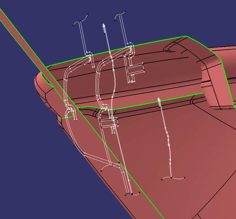
figure 7. master section of arm rest and lower substrate
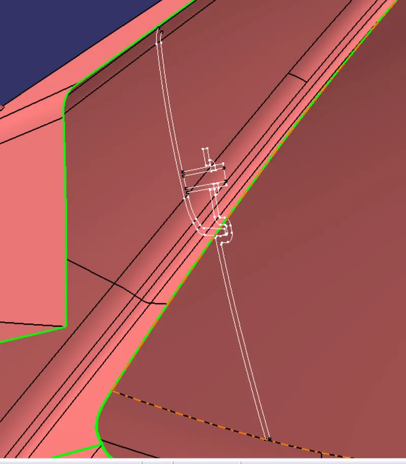
figure 8. master section of lower substrate and map pocket
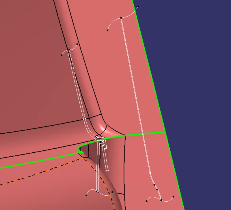
figure 9. master section of lower substrate and map pocket
CLASS A SURFACES
Offset of given surface of armrest to particular distance as per the master section to get the class A of the arm rest. Others given surfaces taken as class A surfaces. it shows in the master section we can see that also.
TOOLING AXIS CREATION
For map pocket :-
Tooling axis is created along the y-axis.
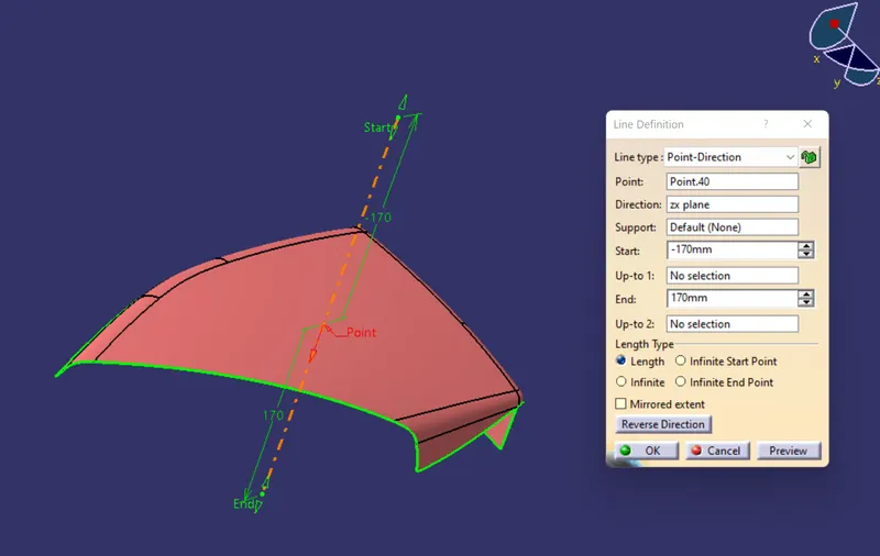
figure 10. map pocket-tooling axis
For bottle holder :-
Tooling axis is created by bisecting x-tooling axis and y tooling axis. X- tooling axis is created by intersecting the surface with zx- plane and extract lines from the intersection and bisect it. Similarly Y- tooling axis is created by intersecting the surface with zy plane and extract lines from the intersection and bisect it.
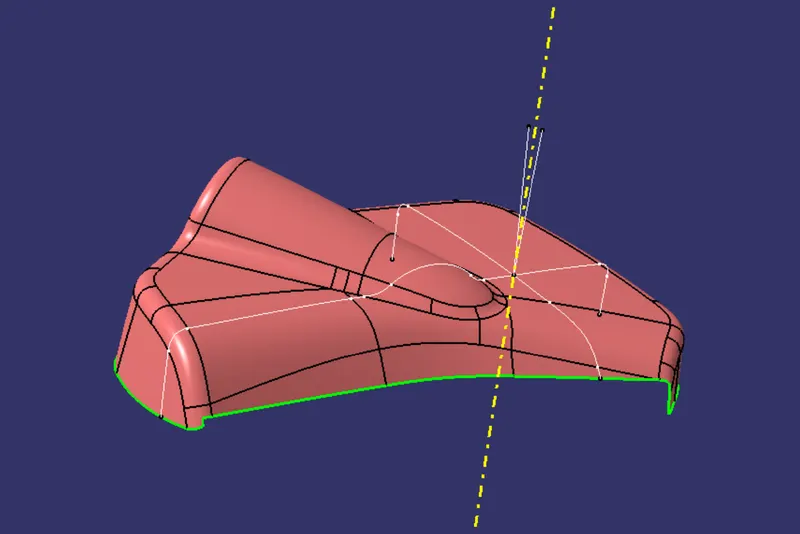
figure 11 . bottle holder-tooling axis
For lower substrate :-
Tooling axis is created along y axis and side core axis is along z axis.
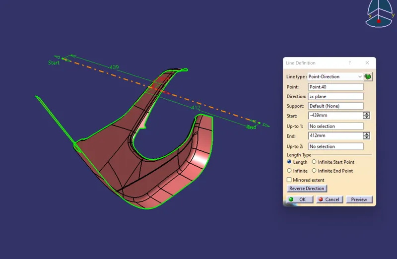
figure 12. lower substrate- tooling axis
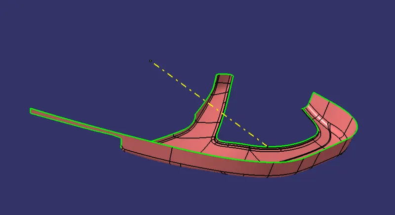
figure 13. lower substrate- side core axis
For arm rest :-
Tooling axis is created by bisecting x-tooling axis and y tooling axis. X- tooling axis is created by intersecting the surface with zx- plane and extract lines from the intersection and bisect it. Similarly Y- tooling axis is created by intersecting the surface with zy plane and extract lines from the intersection and bisect it.
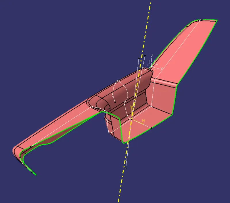
figure 14. arm rest-tooling axis
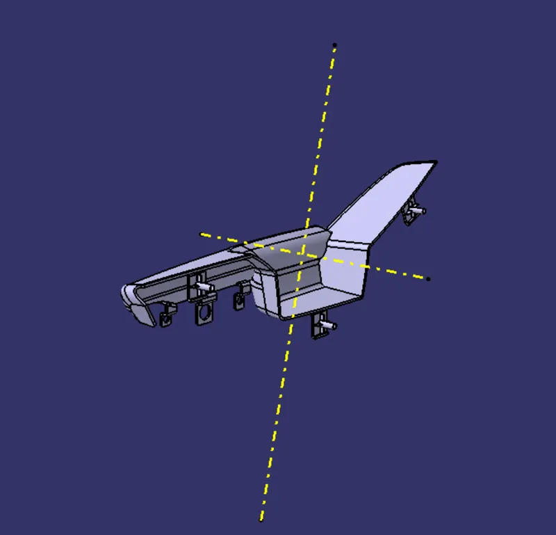
figure 15. side core axis and tooling axis of arm rest
CLASS A DRAFT ANALYSIS
For map pocket :-
Here draft analysis carried for class A surface with respect to tooling axis. Here colour code used is a green colour indicating that the draft is 3 degree or above. The red colour indicates that the draft is 0 and between 0 degree and 3 degree and the blue colour indicates that the draft is minus value. From draft analysis we can see that green colour is all over the surface.
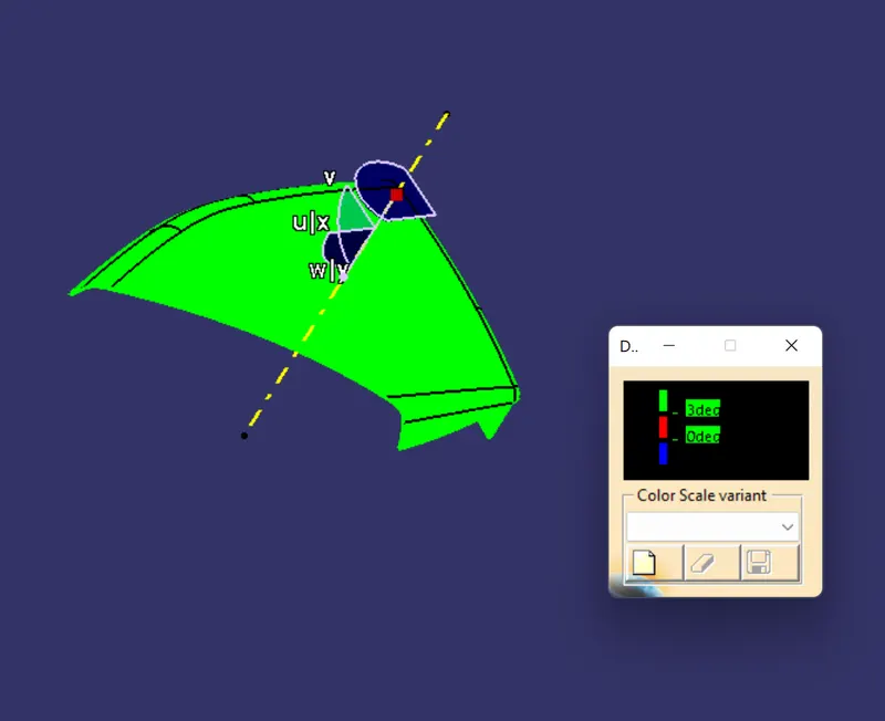
figure 16. class A draft analysis of map pocket
For Bottle holder :-
Here draft analysis carried for class A surface with respect to tooling axis. Here colour code used is a green colour indicating that the draft is 3 degree or above. The red colour indicates that the draft is 0 and between 0 degree and 3 degree and the blue colour indicates that the draft is minus value. From draft analysis we can see that green colour is all over the surface except for some part shown in the figure.
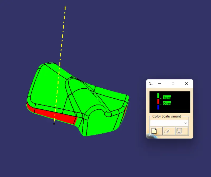
figure 17. draft analysis of bottle holder
For lower substrate :-
Here draft analysis carried for class A surface with respect to tooling axis. Here colour code used is a green colour indicating that the draft is 3 degree or above. The red colour indicates that the draft is 0 and between 0 degree and 3 degree and the blue colour indicates that the draft is minus value. From draft analysis we can see that green colour is all over the surface.
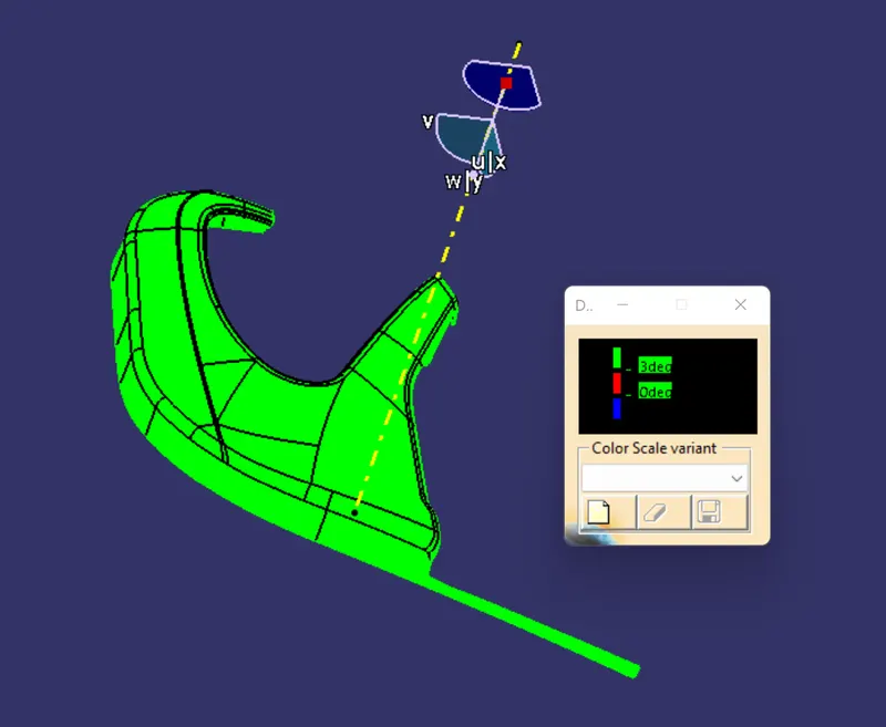
figure 18. class A draft of lower substrate
For arm rest : -
Here draft analysis carried for class A surface with respect to tooling axis. Here colour code used is a green colour indicating that the draft is 3 degree or above. The red colour indicates that the draft is 0 and between 0 degree and 3 degree and the blue colour indicates that the draft is minus value. From draft analysis we can see that green colour is all over the surface except for some part shown in the figure.
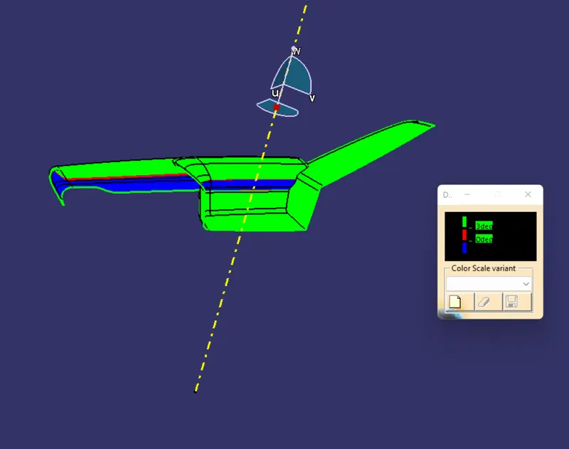
figure 19. class A draft analysis of arm rest
SOLID DRAFT ANALYISIS
For map pocket :-
Here we need to check the draft of map pocket , heat stakes and locator along tooling axis. First check for the map pocket, we have to set colour for the draft analysis with minimum draft of 3 degrees. Here colour code used is a green colour indicating that the draft is 3 degree or above. The red colour indicates that the draft is 0 degree and the blue colour indicates that the draft is minus value. From draft analysis we can see that green color over the surface of the map pocket.
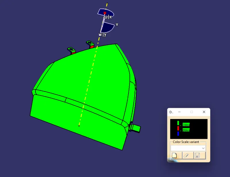
figure 20. draft analysis with 3 degree
Next we have to check with the heat stakes and locator along tooling axis. Here we have to set colour for the draft analysis with minimum draft of 0.48 degrees. Here colour code used is a green colour indicating that the draft is 0.48 degree or above. The red colour indicates that the draft is 0 degree and the blue colour indicates that the draft is minus value. From the draft analysis we can see that green colour over the surfaces of heat stakes and locator.
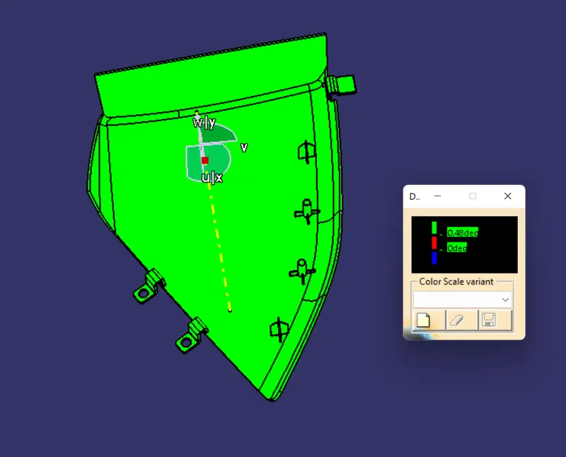
figure 21. draft analysis with 0.48 degree
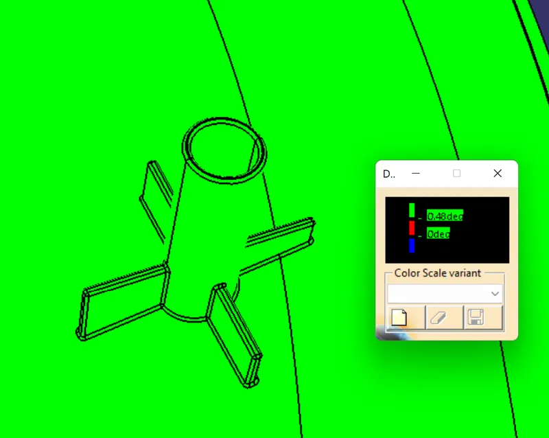
figure 22. draft analysis of heat stakes
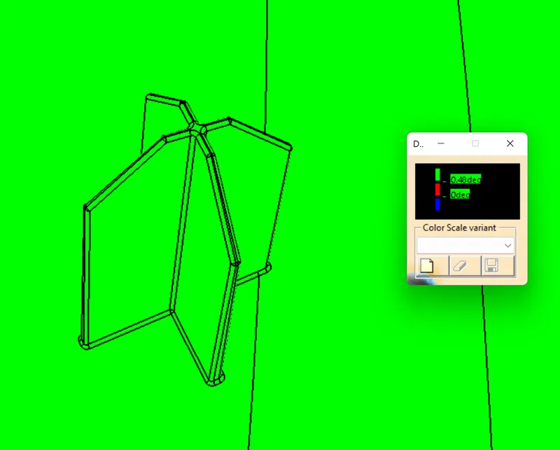
figure 23. draft analysis of heat stakes
For Bottle holder :-
Here we need to check the draft of bottle holder along tooling axis. First we have to set colour for the draft analysis with minimum draft of 3 degrees. Here colour code used is a green colour indicating that the draft is 3 degree or above. The red colour indicates that the draft is 0 degree and the blue colour indicates that the draft is minus value. From draft analysis we can see that green color over the surface except for some part.
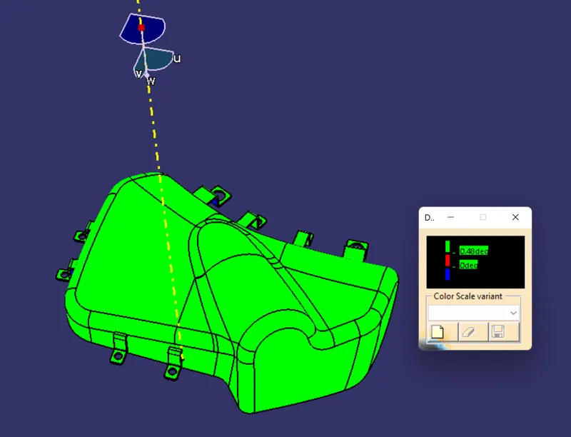
figure 24. draft analysis of bottle holder
For lower substrate: -
Here we need to check the draft of lower substrate , heat stakes locator and dog house . First check for the lower substrate and outer surface of dog house we have to set colour for the draft analysis with minimum draft of 3 degrees. Here colour code used is a green colour indicating that the draft is 3 degree or above. The red colour indicates that the draft is 0 degree and the blue colour indicates that the draft is minus value. From draft analysis we can see that green color over the surface of the lower substrate and dog house outer surface got green when the green value changed to 2.9 degrees.
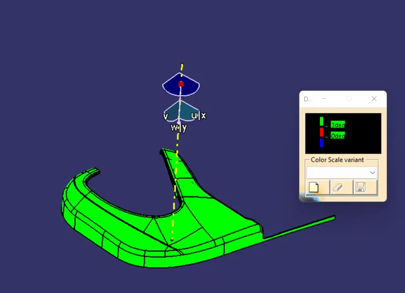
figure 25. draft analysis of lower substrate
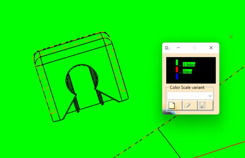
figure 26. draft analysis of outer surface of dog house
Next we have to check with the heat stakes and locator along tooling axis. Here we have to set colour for the draft analysis with minimum draft of 0.48 degrees. Here colour code used is a green colour indicating that the draft is 0.48 degree or above. The red colour indicates that the draft is 0 degree and the blue colour indicates that the draft is minus value. From the draft analysis we can see that green colour over the surfaces of heat stakes and locator.
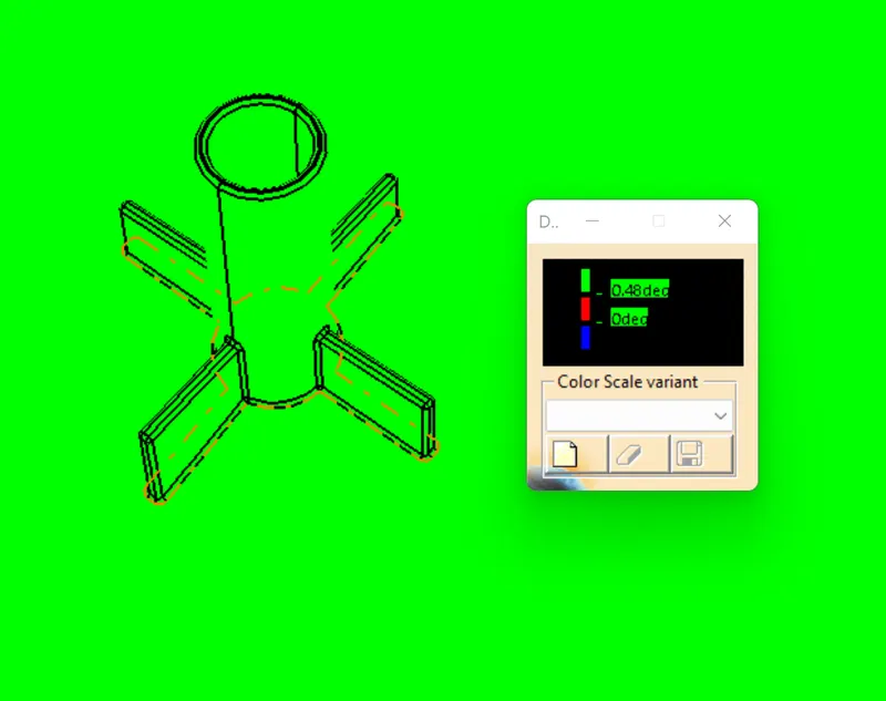
figure 27. draft analysis of heat stakes
figure 28. draft analysis of locator
Next we have to check with the dog house along side core axis. Here we have to set colour for the draft analysis with minimum draft of 0.48 degrees. Here colour code used is a green colour indicating that the draft is 0.48 degree or above. The red colour indicates that the draft is 0 degree and the blue colour indicates that the draft is minus value. From the draft analysis we can see that green colour over the surfaces in side the dog house .
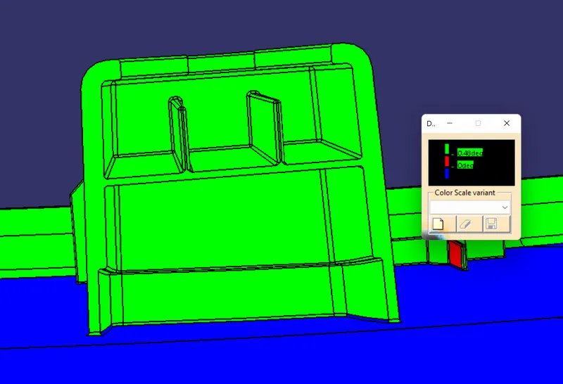
figure 29 . draft analysis of dog house with respect to side core axis
For arm rest :-
Here we need to check the draft of arm rest along tooling axis. First we have to set colour for the draft analysis with minimum draft of 3 degrees. Here colour code used is a green colour indicating that the draft is 3 degree or above. The red colour indicates that the draft is 0 degree and the blue colour indicates that the draft is minus value. From draft analysis we can see that green color over the surface except for some part. and also checked the draft analysis of heat stakes with respect to side core axis and it gets green all over the surface of the heat stakes.
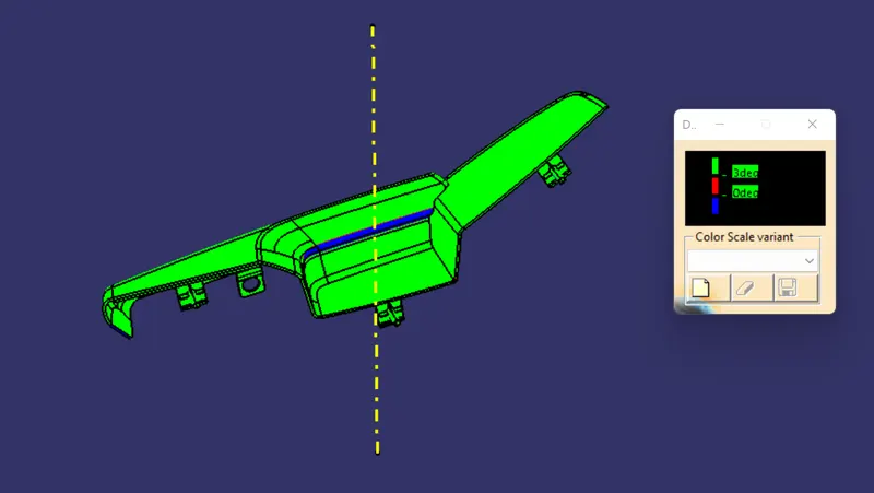
figure 30. draft analysis of arm rest
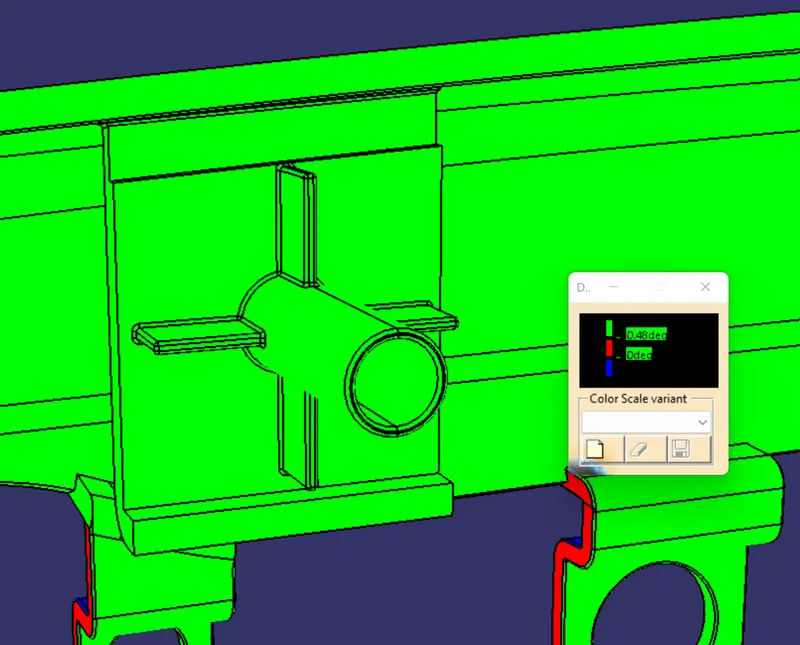
figure 31 . heat stakes draft analysis
COMPONENT VIEWS
Map pocket’s views : -
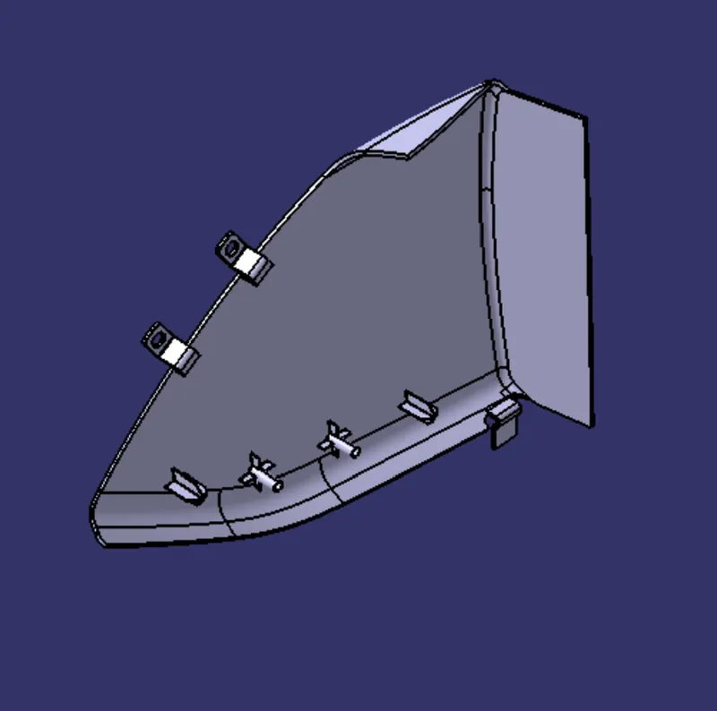
figure 32. isometric view
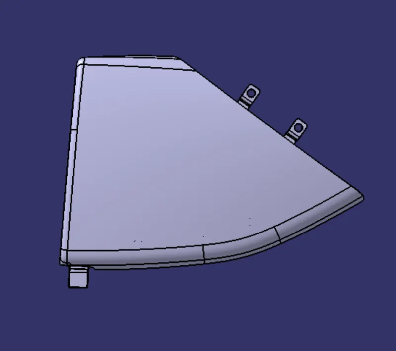
figure 33. left side view
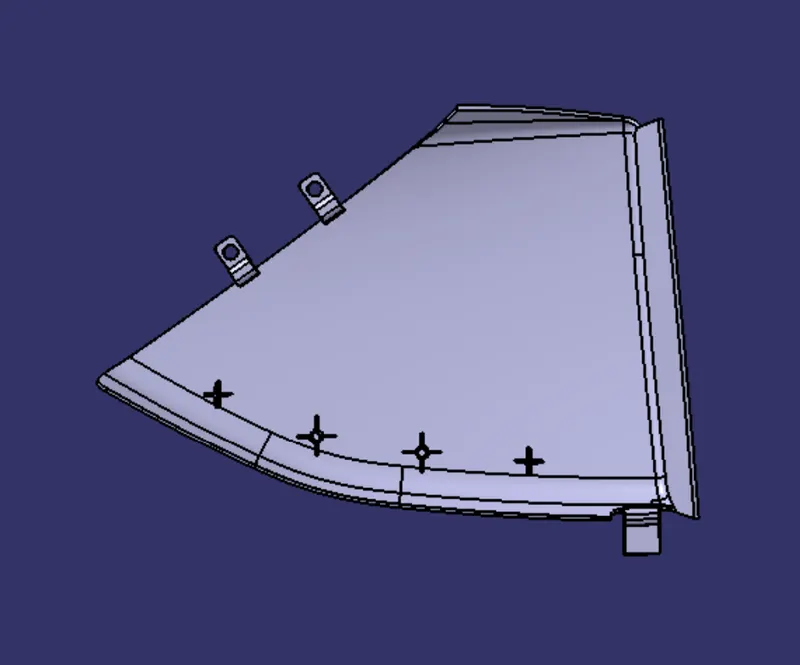
figure 34. right side view
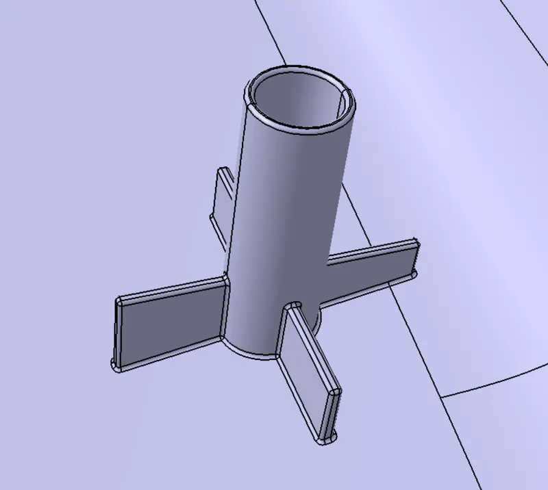
figure 35. heat stake
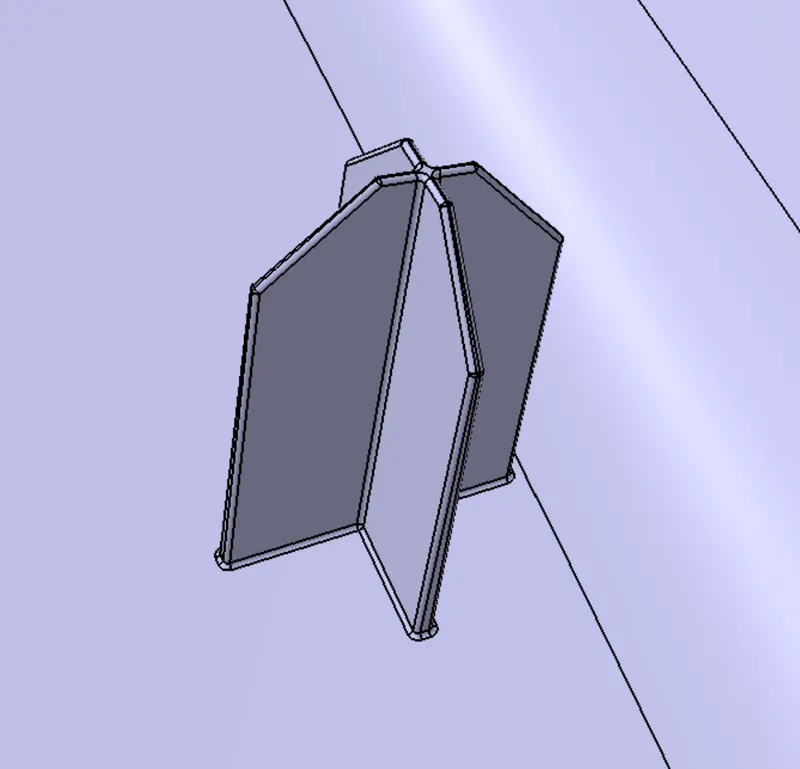
figure 36. locator
Bottle holder’s views :-
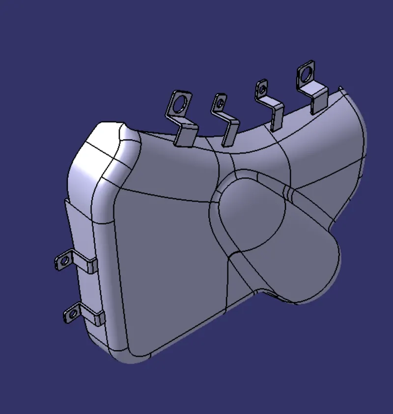
figure 37. isometric view
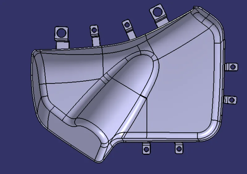
figure 38. left side view
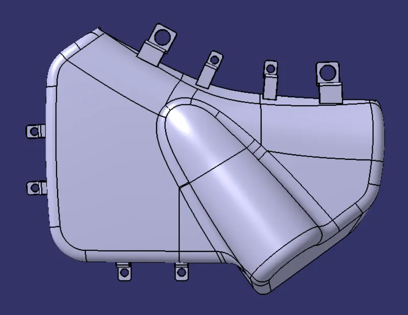
figure 39. right side view
Lower substrate’s views :-

figure 40. isometric view
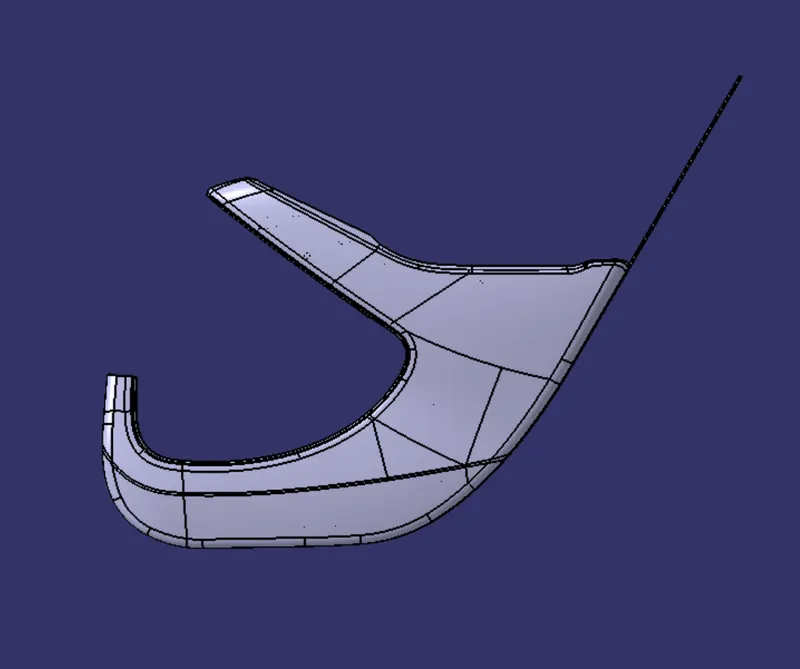
figure 41. left side view
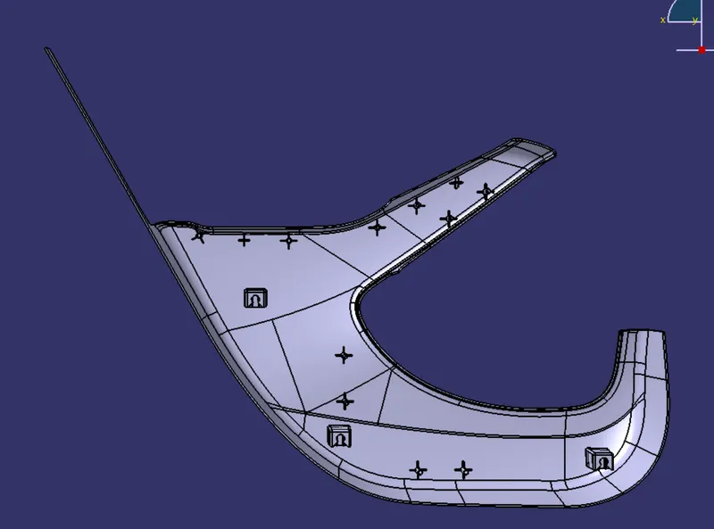
figure 42. right side view
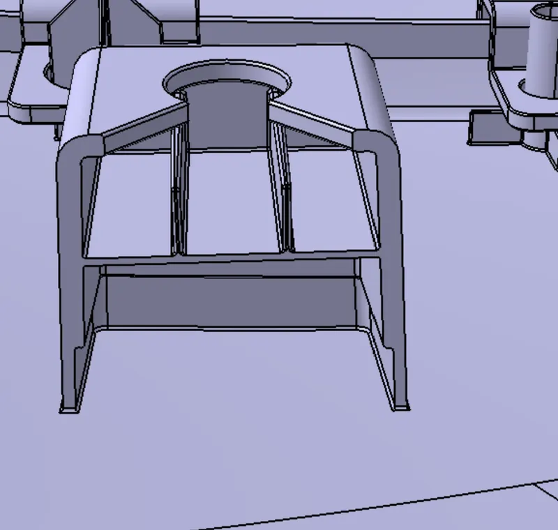
figure 43. dog house
Arm rest’s views :-
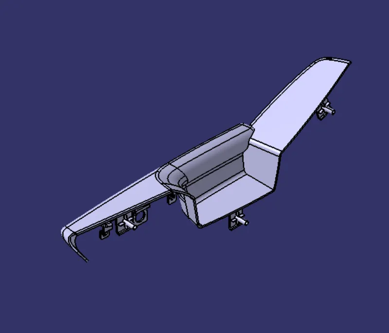
figure 44. isometric view
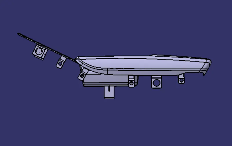
figure 45. left side view
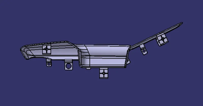
figure 46. right side view
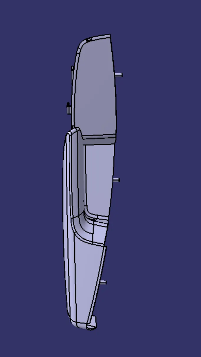
figure 47. top view
Push pin’s view :-
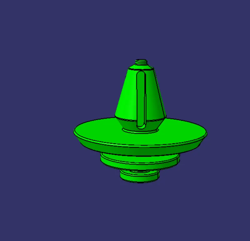
figure 48. push pin
ASSEMBLED DOOR TRIM PANEL VIEWS
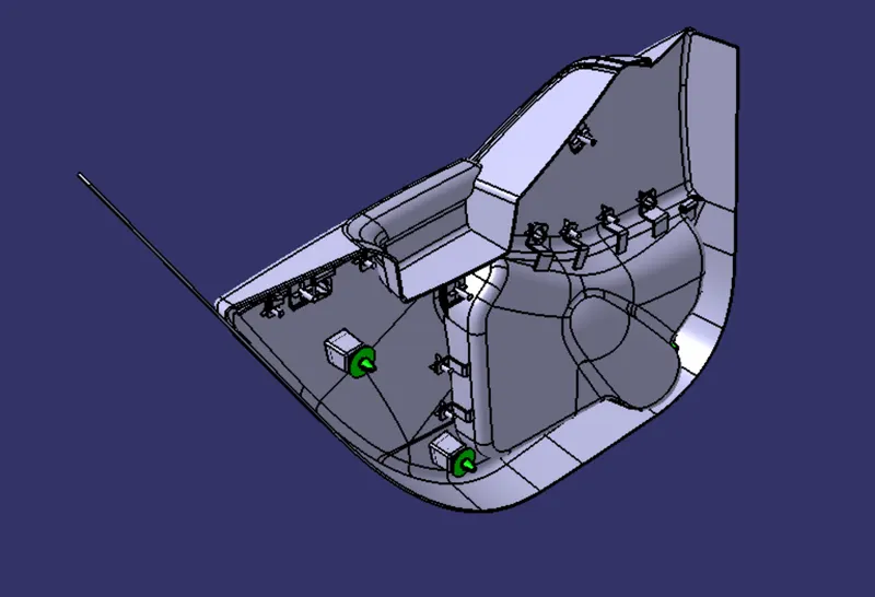
figure 49. isometric view
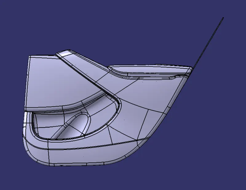
figure 50. left side view
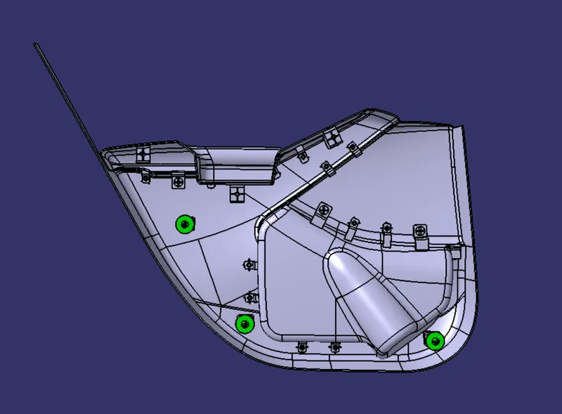
figure 51. right side view
TREE STRUCTURE
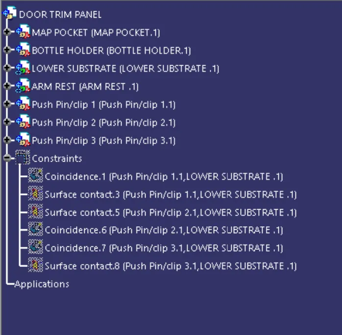
figure 52. tree strucure of door trim panel
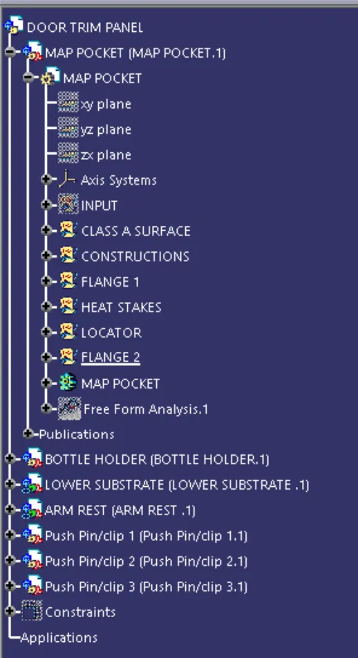
figure 53. tree structure of map pocket
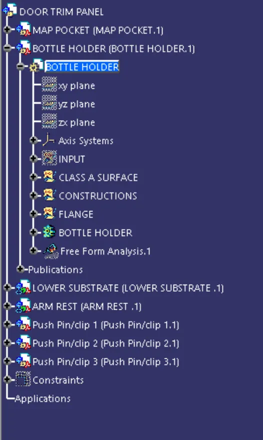
figure 54. tree structure of the bottle holder
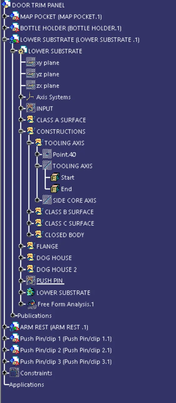
figure 55. tree structure of lower substrate
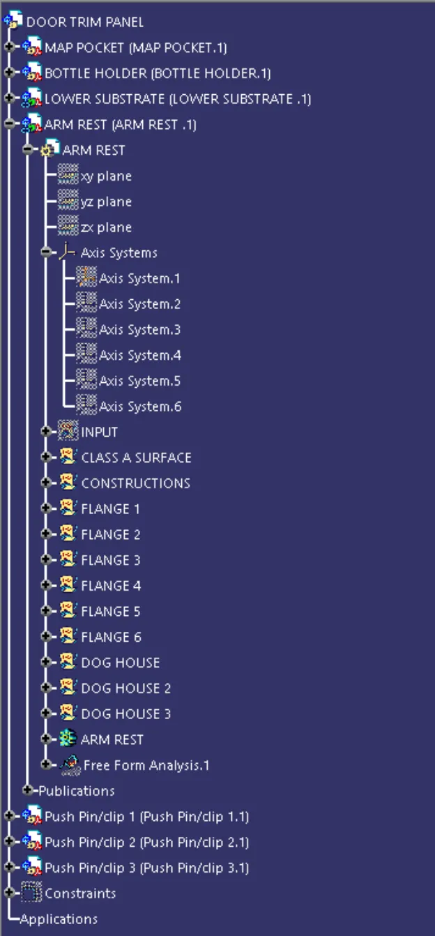
figure 56. tree structure of arm rest
CONCLUSION
Each component of door trim panel is created with proper fixation strategy.