Week 11 - Final project
AIM:
- To design and model the automobile interior door trim product using the CATIA v5.
INTRODUCTION:
- Automotive interior door trim product is made of plastic materials.
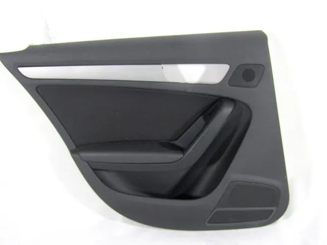
- The interior door trim is attached to the door's inner side. The door panel covers internal parts like the window regulator, power window motor, and wiring, It is attached to the sheet metal part of the door.
- This product improves the appearance of a number of design requirements in terms of protection, aesthetics, and functionality among other things.
DOOR TRIM:
- Door panels serve as an interface between the interior of the car and the inner workings of the door and between vehicle occupants and the door.
- They are expected to meet a variety of design specifications.
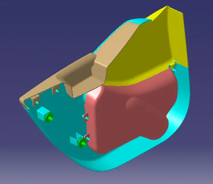
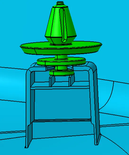
- Door trim comprises the B-side engineering features like Heat Stakes, Dog house, Pushpin, and Flanges to fix the plastic door trim with sheet metal components.
- And it also provides more strength and avoids plastic defects in the product.
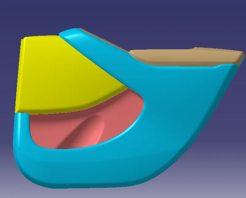
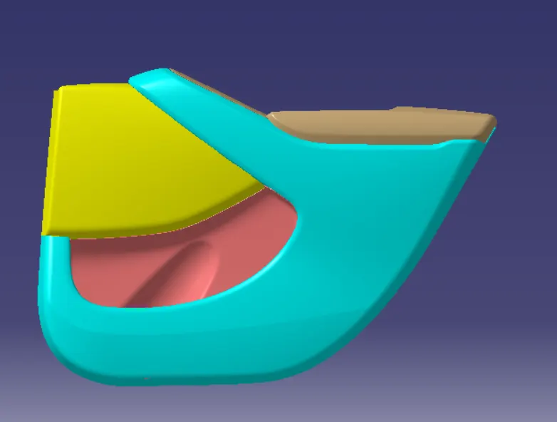
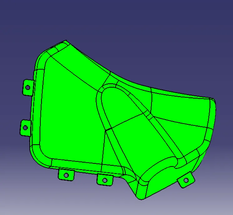
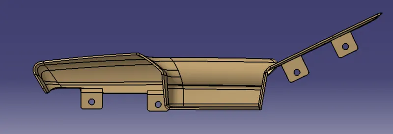
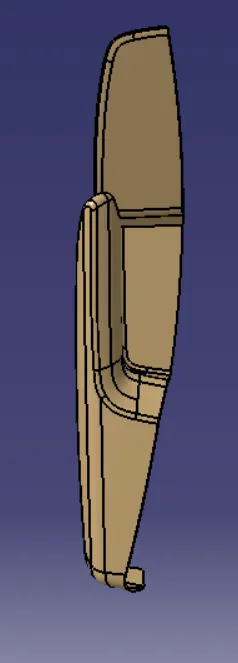
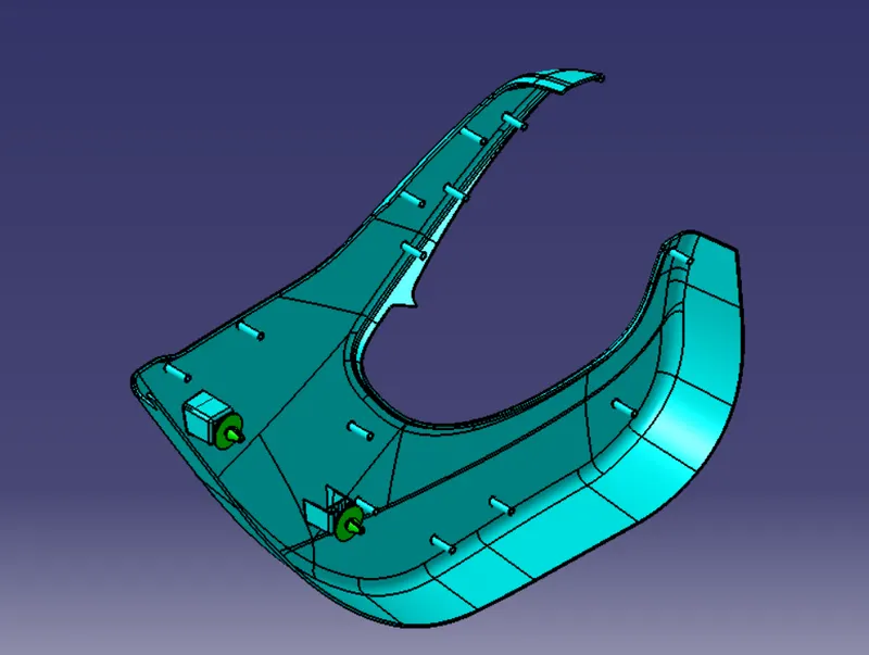
- It consists of four sub-parts such as the Armrest, Lower substrate, Upper map pocket, and Lower map pocket.
CREATION OF INTERIOR DOOR TRIM THROUGH THE FOLLOWING STAGES:
1. CLASS A SURFACE
2. CLASS B SURFACE
3. CLASS C SURFACE
4. ENGINEERING ATTACHING FEATURES
5. DRAFT ANALYSIS.
PRIMARY NEEDS TO DESIGN THE DOOR TRIM:
- To design the door trim panel you should have the parent surfaces(CLASS A SURFACES) by using the reference of the parent surface we can design the folowing class Band C surfaces.After creating the class B and C surfaces, combined or join the surfaces with each other to get the closed surface body.
- The closed surface bodyto be converted into the closed solid body model.
CLASS- A SURFACE:
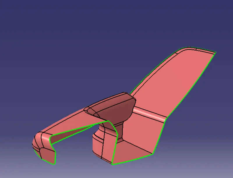
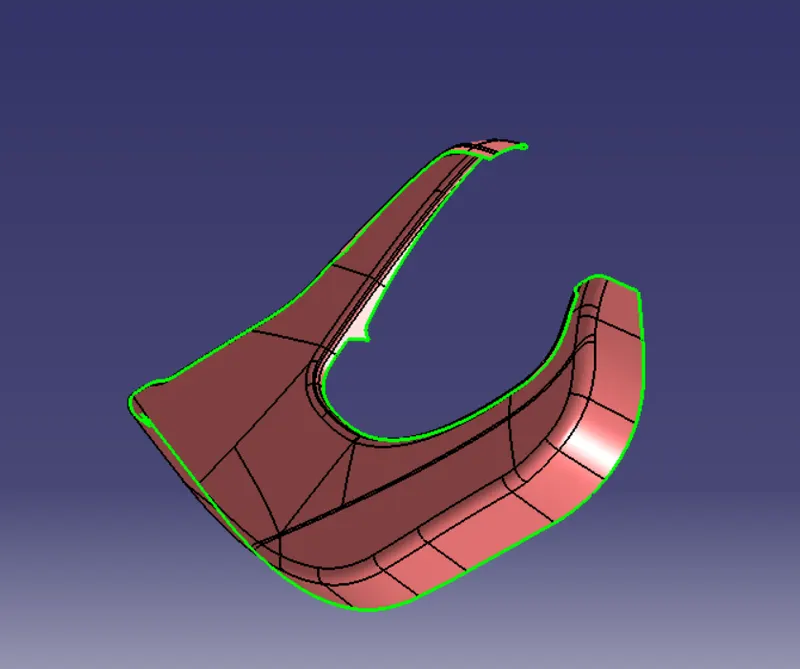
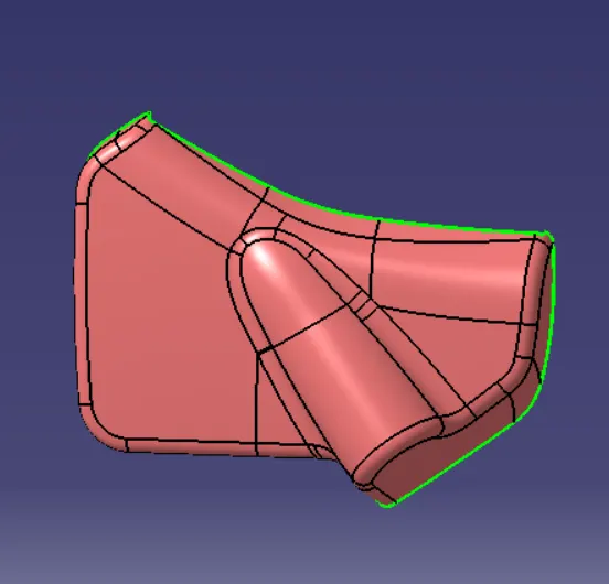
- Class-A surface is given as an input surface by designers.
- Generally the class-A surfaces have the tangent continuity
- Class-A surface is the outermost aesthetic surface.
CLASS A SURFACE OF ARMREST:
CLASS A SURFACE OF LOWER SUBSTRATE:
CLASS A SURFACE OF UPPER MAP POCKET: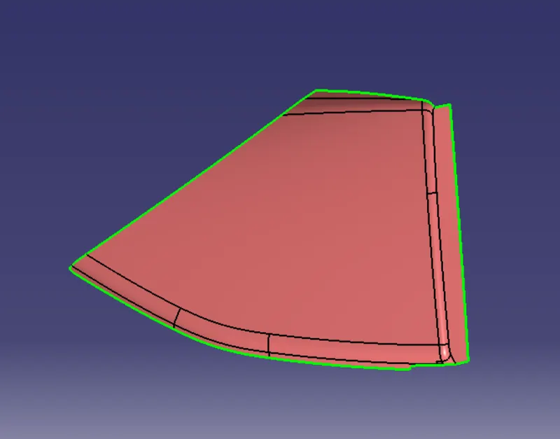
CLASS A SURFACE OF LOWER MAP POCKET:
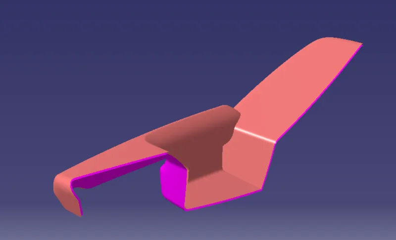
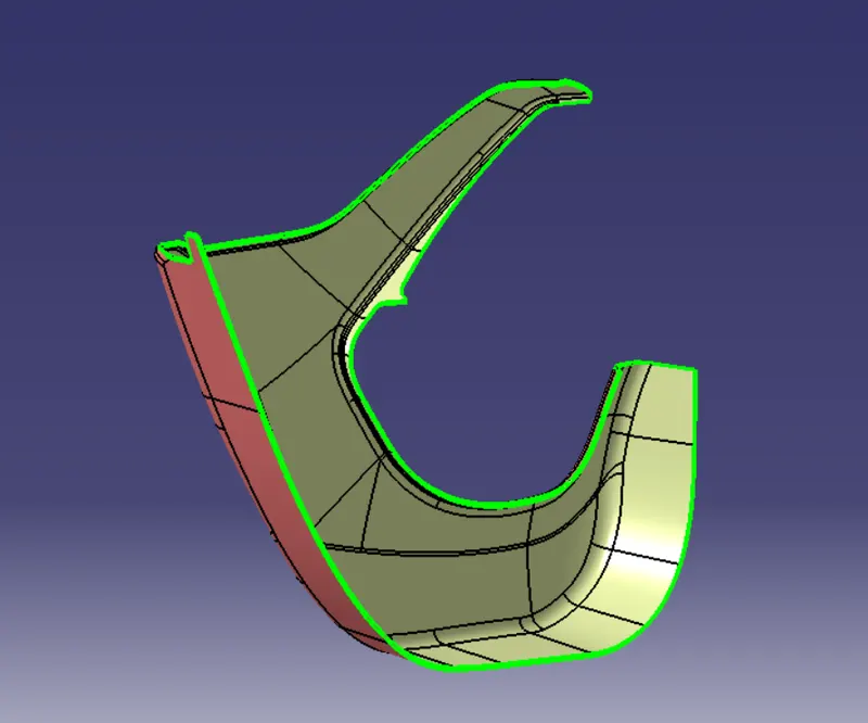
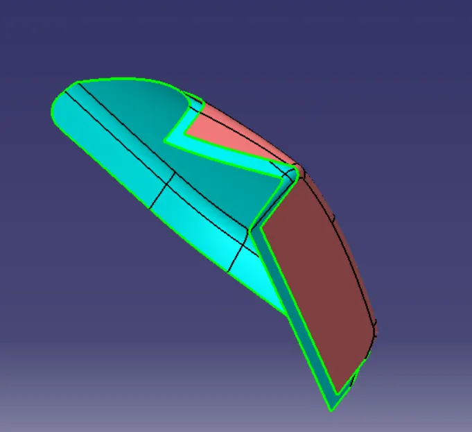
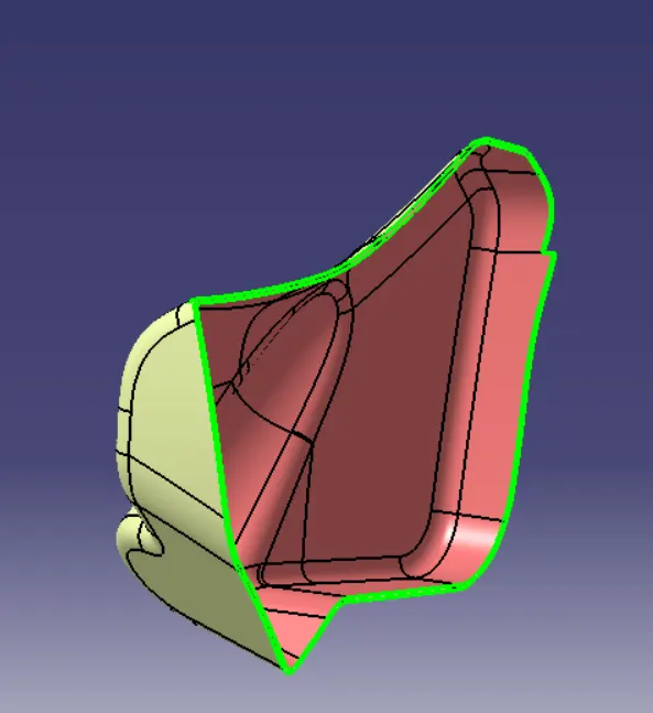
CLASS B SURFACE :
- Class B surface is an engineering surface.
- The engineering features of ribs, screw boss, dog house, heat stakes, and locators are designed on the class B surface.
- Class B surface is created by the offset of class A surface.
- Class B surface is lying under the class A surface to create the engineering features.
CLASS B SURFACE OF ARM REST:
CLASS B SURFACE OF LOWER SUBSTRATE:
CLASS B SURFACE OF UPPER MAP POCKET;
CLASS B SURFACE OF LOWER MAP POCKET:
CLASS C SURFACE:
- Class C surface is the closing surface of class A and class B surfaces.
- It is the extraction of the boundary of class A surface.
- Apply the sweep feature to create the class c surface, For guide reference click the extracted boundary and for the drafting reference option click the tooling axis and give a 3-degree draft angle.
CLASS C SURFACE OF ARM REST:
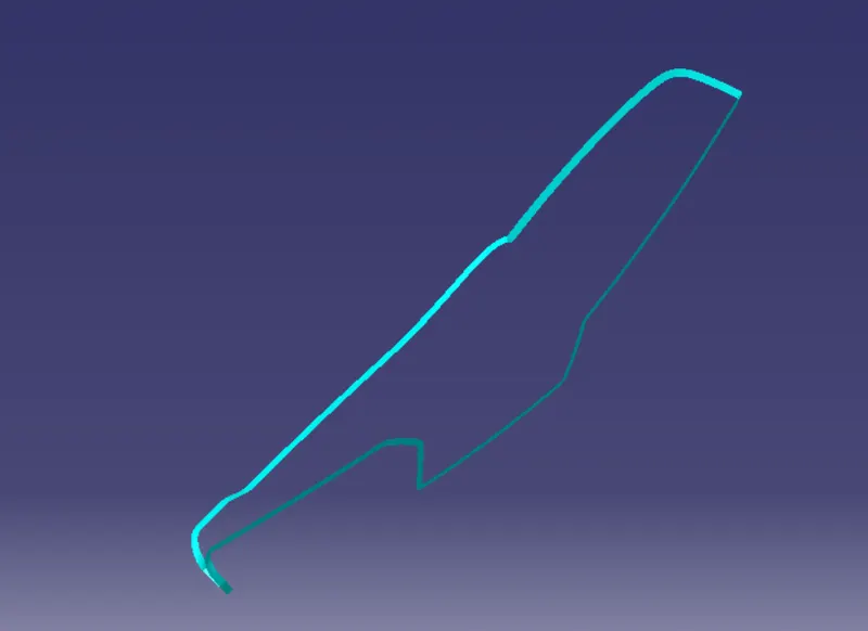
CLASS C SURFACE OF LOWER SUBSTRATE:
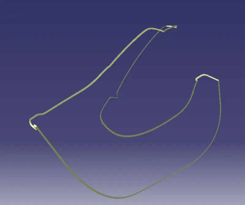
CLASS C SURFACE OF UPPER MAP POCKET:
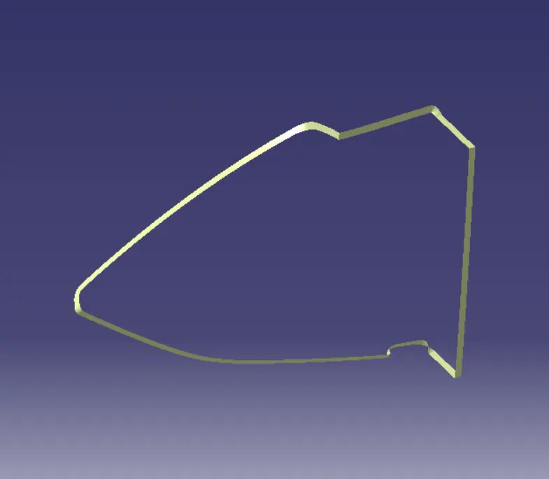
CLASS C SURFACE OF LOWER MAP POCKET:

MASTER SECTION:
- Master sections are the guides for design requirement which decide the component packaging after technical styling.
ENGINEERING ATTACHING FEATURES:
- After the closed volume design next step to generate features for mount the door on the panel for fixation.
- The Mounting features are heat stakes, ribs, push pin, and flanges are designed by using the reference of master section.
DOG HOUSE:
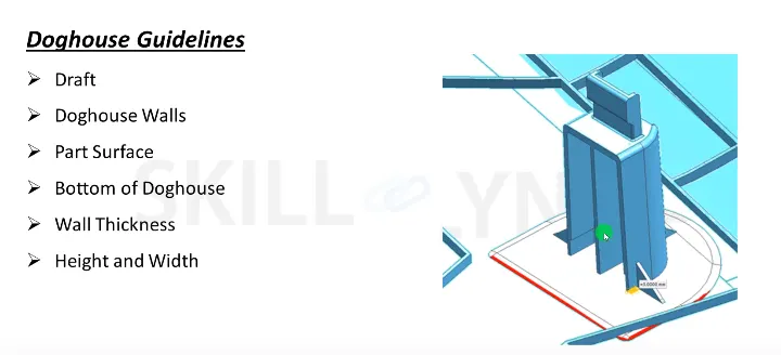
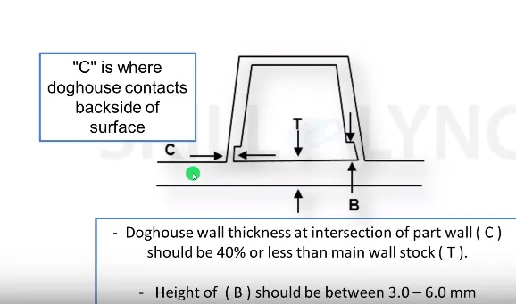
- Dog house is an salient enginnering feature contributes to avoid the plastic defects ( sink marks) on the class A surface, and reduces the length factor of screw bosses and locators while mounted on the dog house
- It also improves the strenth of components.
DESIGN RULE FOR DOG HOUSE:
- Draft 1.5 degree on all walls
- Intersection of part wall Thickness= 0.4* T
- Height =3<->6mm
- Width of dog house =12 mm
- Fillet value 0.25mm
HEAT STAKES:
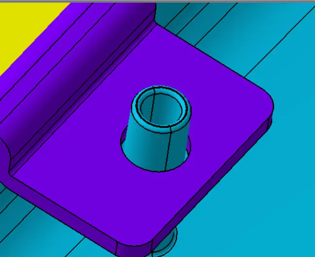
- Heat stake is an engineering feature attached on the components class B surface side.
- Multi-heat stakes to be located near the edge of the door trim.
SIGNIFICANCE:
- Heat staking is all about the process of connecting different components into a cohesive functioning unit.
- The application is very common with the assembly of products that involve plastic and resin parts.
- The plastic joining strategy that is part of heat staking helps to strengthen the overall structure of manufactured items and provides a high degree of stability.
JOINING TECHNOLOGY OF DIFFERENT COMPONENTS BY HEAT STAKES:
- The basic concept behind heat staking involves joining the components at pre-molded interfaces.
- A Plastic stud that is attached to one component would be inserted into the hole found on the accompanying part.
- Once the two components are joined, the end of the stud is softened and heated to allow the formation of a larger head that will hold the stud firmly in the hole.
- After the components are joined, the temperature is raised to allow the head of the stud to soften. At the same time pressure is applied to create a head on the stud that is wider than the hole that is housing the body of the stud.
HEAT STAKES WITH FLANGE:
FLANGES:
- Flange is a protruded ridge, lip, or rim, either external or internal, that serves to increase strength for easy attachment/ transfer of contact force with another object.
DRAFT ANALYSIS:
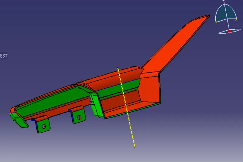
- The analysis of the model should maintain the nominal 3-degree draft angle to the tooling axis.
- Draft analysis reveals the manufacturing feasibility of the component, whether the designed part is able to manufacture or not without maintaining the nominal draft angle.
- Draft should be given to the plastic component to reduce the wear and tear and improve the production quality and accuracy while ejecting the part from the mold cavity.
How to perform the draft analysis:
1. Go to view mode customization and change to material mode.
2. Go to insert < analysis< feature draft analysis.
3. Align the tooling axis with a compass.
4. Click on the surface to see whether it is in permissible limit draft values or not.
5. The entire surface should be green in color.
DRAFT ANALYSIS OF ARM REST USING MAIN TOOLING AXIS;
DRAFT ANALYSIS OF ARMREST USING SIDE CORE AXIS:
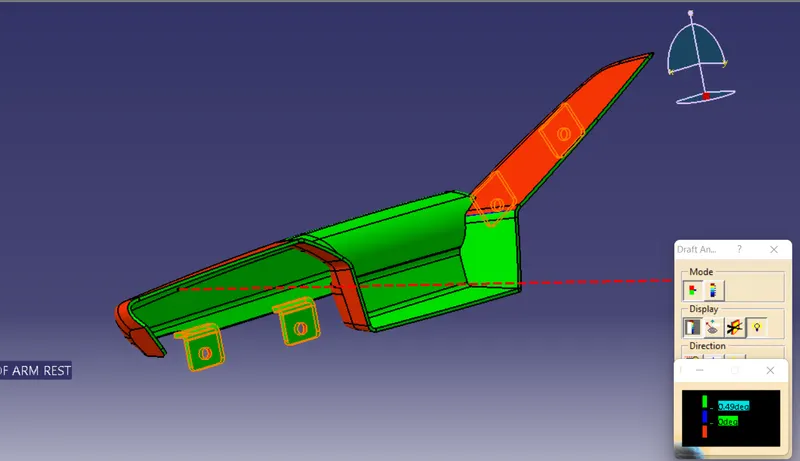
DRAFT ANALYSIS OF LOWER SUBSTRATE:
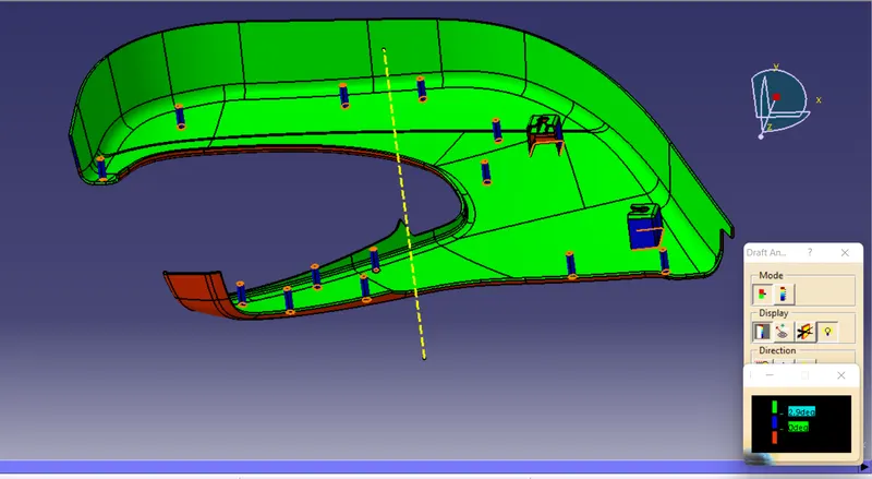
DRAFT ANALYSIS OF LOWER SUBSTRATE WITH SIDE CORE AXIS
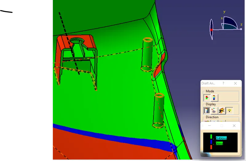
DRAFT ANALYSIS OF UPPER MAP POCKET
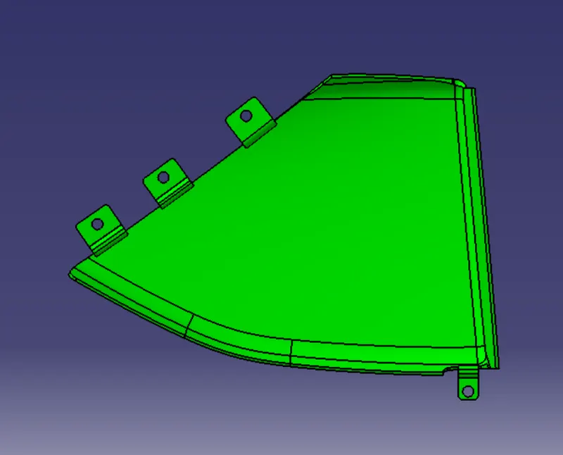
DRAFT ANALYSIS OF LOWER MAP POCKET:
ARM REST IMAGGES:
LOWER SUBSTRATE IMAGES:
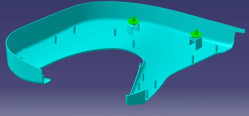
UPPER MAP POCKET
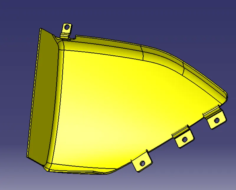
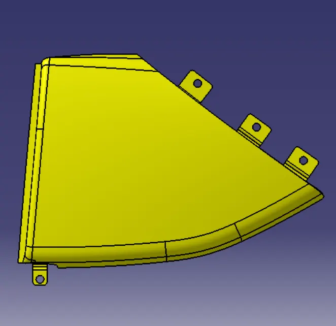
LOWER MAP POCKET
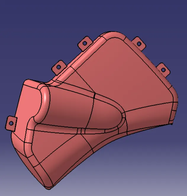
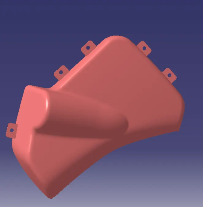
DOOR TRIM ASSEMBLY PRODUCT TREE IMAGE