Photo Realistic Rendering
DESIGN AND ASSEMBLY OF AMERICAN CHOPPER
OBJECTIVE:
- To design and model the american chopper using solidworks.
- Modelling the each part of american chopper.
- Assembly all modeled parts to get the chopper.
- Rendering the american chopper by the apply of appearance and decals.
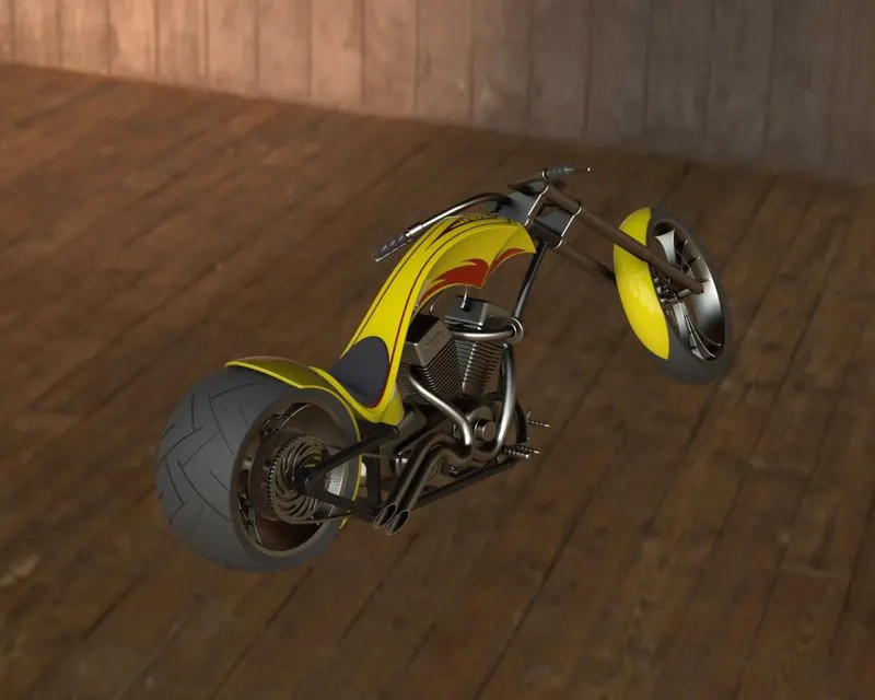
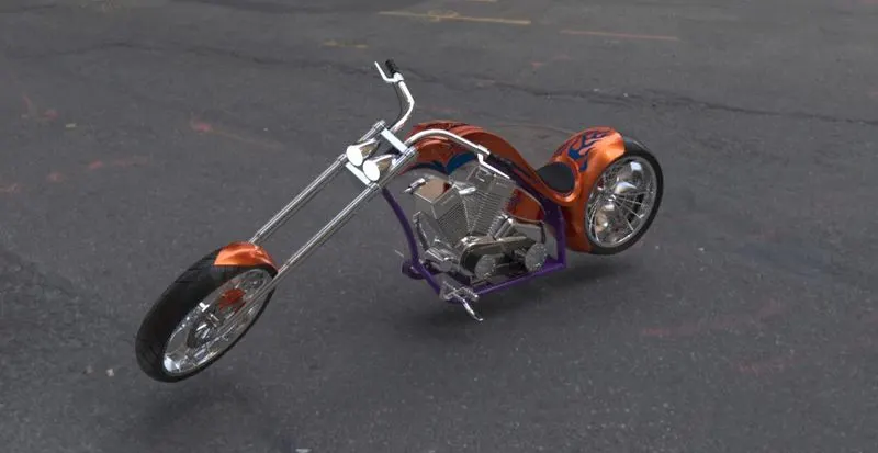
- Build the assembled chopper as a photorealistic render of environment.
INTRODUCTION:
- Solidworks is a mechanical 3D CAD ( computer-aided design) software.
- It helps to designing & modelling the components (or) parts.
- Modelling the complex structure of components by using the apply of solidworks tools, commands, features.
- It can also helps to render the parts.
DESIGN METHODOLOGY:

MODELED PARTS OF AMERICAN CHOPPER:
- TRANSMISSION BELT
- KICKSTAND (OR) SIDESTAND
- FRONT FENDER
- REAR FENDER
- CHAIN
- OIL TANK
- FRONT WHEEL
- REAR WHEEL
- FRONT FORK
- CHASSIS
- ENGINE
- GAS TANK
EXPLANATION OF FEATURES:
PLANE:
- To draw the section view of the parts.
- To draw the particular portion (or) side of part.
SKETCH:
- To draw the part by applying the command and smart dimensions at particular plane.
FILLET:
- It creates the round shapes at corner of the edge of part.
CHAMPER:
- It creates the sloping/tapered shape at corner of the edge.
CONVERT ENTITIES:
- It gives the same sketch profile on the same plane (or) other plane with same dimension value.
OFFSET ENTITIES:
- It creates the same sketch profile from selected model edges by specified distance.
MIRROR ENTITIES:
- When you create mirrored entities, apply a symmetric relation between each corresponding pair of sketch points.
SHELL:
- The shell tool creates hollows out the inside of the solid, leaving a shell of a specified wall thickness.
EXTRUDE BOSS/BASE:
- Extrude tool is used to extend the sketch in one or two direction with solid feature.
REVOLVED BOSS/BASE:
- It is used to create the revolved solid body sketch with reference of axis or lines.
EXTRUDE CUT:
- It is used to remove the materials from solid body in either one or two direction.
REVOLVE CUT:
- It is used to remove the materials from revolved solid body sketch in either one or two direction.
SWEPT BOSS/BASE:
- It creates the solid body around the sketch profile along an open & closed path.
LOFT:
- This feature creates a complex shape between the multiple profiles & guide curves.
DOME:
- It creates tangent to adjacent cylindrical & conical surfaces.
TRIM:
- It is used to remove the extra line of the surface.
PATTERN:
- It creates the number of sketch profiles through selected sketch along the reference path.
SPLIT:
- The split tool is used to project onto other surface or curved planar surfaces.
PROJECTED CURVE:
- Project the sketched curve on the model face & combines with another 2D curve to get the 3D curve.
APPEARANCE:
- By using this get the different look & apply the different appearances.
DECALS:
- By using this feature painted stickers to be applied on the model of chopper.
EXPLANATION OF PARTS:
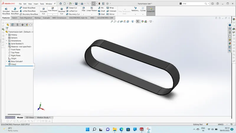
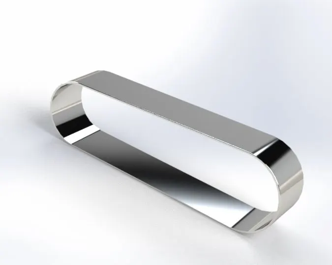
1. TRANSMISSION BELT :
- It is a loop of flexible materials used to link two or more pulley.
- It transmits the power or motion without losing synchronisation.
- Forces are transmitted from the input pulley to the belt & then from the belt back to the output pulley.
- The transmission belt made using the matte rubber materials.
SKETCH TOOLS:
- 3 Point arc
- Line
- Circle
- Trim
- Offset entities
FEATURES:
- Extrude
- Fillet
- Appearance
2. KICKSTAND OR SIDESTAND:
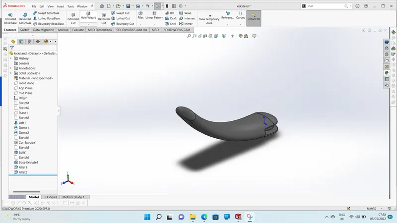
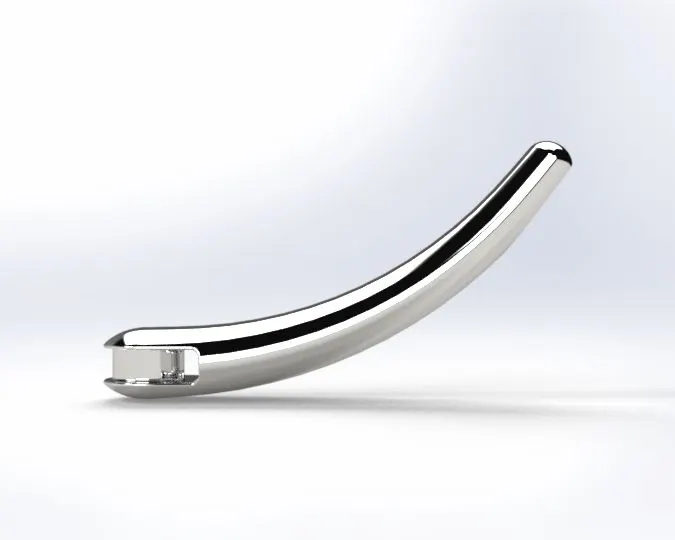
- Kickstand or side stand is a mechanical component used to support the motorcycle in rest position.
- The kickstand is mounted on the chassis through mounting point.
- It has high tensile/compressive stress to withstand the load of the bike.
SKETCH TOOLS:
- Ellipse
- Spline
- Pierce
FEATURES:
- Loft
- Split
- Dome
- Extruded boss
- Extruded cut
- Fillet
- Appearance
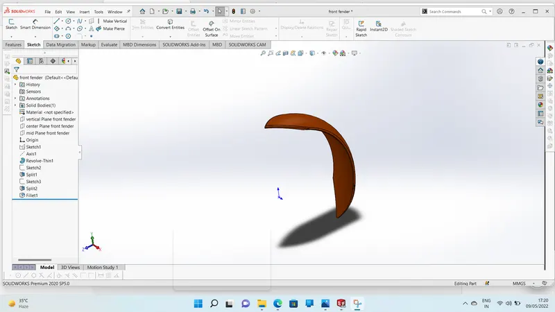
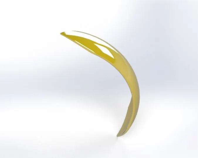
3. FRONT FENDER:
- It is an automobile part or other vehicle body that frames wheel well.
- The primary purpose is to prevent sand, mud, rocks, liquids and other road spray being thrown into air by rotating tire.
- A fender is mounted over the wheel
- A front wheels require fender to provide mud & gravel protection on the rear side.
- The fender openings for the wheels well tend to be much larger than the diameter of the tires.
SKETCH TOOLS:
- 3 Point arc
- Offset entities
- Line
- Spline
FEATURES:
- Revolve
- Split
- Mirror entities
- Fillet
- Appearance
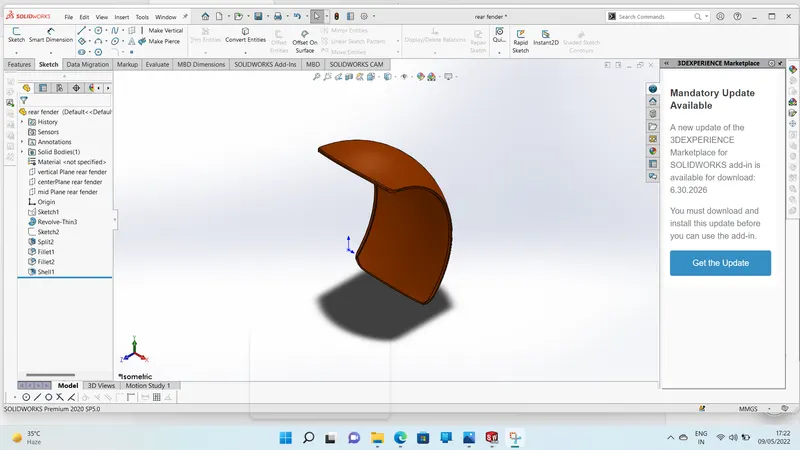
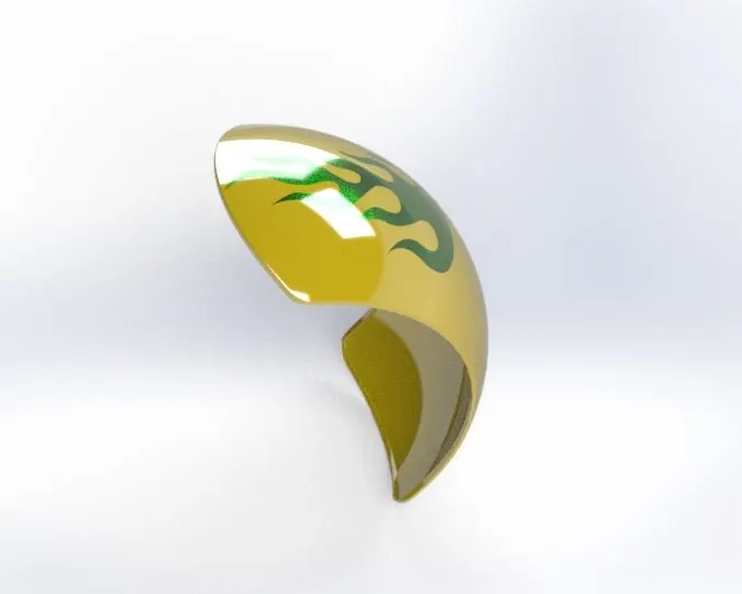
4. REAR FENDER:
- It is an automobile part or other vehicle body that frames wheel well.
- The primary purpose is to prevent sand, mud, rocks, liquids and other road spray being thrown into air by rotating tire.
- A fender is mounted on the wheel.
- The rear wheels require fender to provide mud & gravel protection on the front side.
- The fender openings for the wheels wells tend to be much larger than the diameter of tires.
SKETCH TOOLS:
- 3 Point arc
- Offset entities
- Line
- Spline
FEATURES:
- Revolve
- Split
- Shell
- Mirror entities
- Fillet
- Appearance
5. OIL TANK:
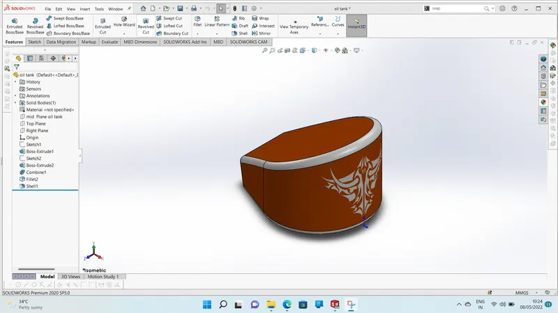
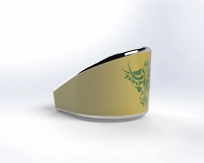
- Oil tank is a tank that holds the capacity of oil to cool the bike.
- The oil tank is located below the rear seat on the top of the gearbox.
- In the American chopper we have used the oil tank for engine lubrication & cooling.
SKETCH TOLS:
- 3 Point arc
- Line
FEATURES:
- Extruded boss/base
- Fillet
- Combine
- Shell
- Appearance
6. CHAIN:
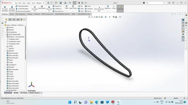
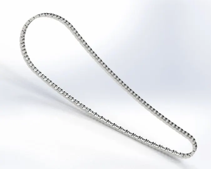
- It is a way of transmitting mechanical power from one place to another.
- It is often used to convey power to the wheels of the bike.
- Chain pins are properly mating with sprocket without slip while run.
SKETCH TOOLS:
- 3 Point arc
- Centrepoint slots
- Circle
FEATURES:
- Extruded boss
- Make and save block
- Fillet
- Curve driven pattern
- Mirror
- Appearance
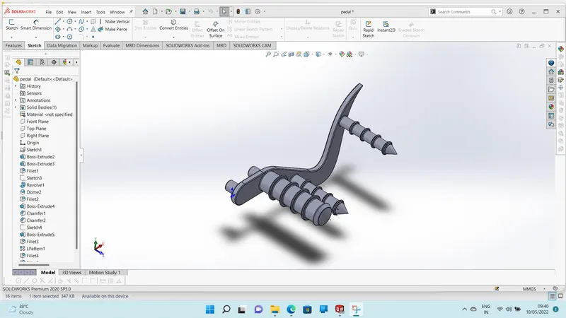
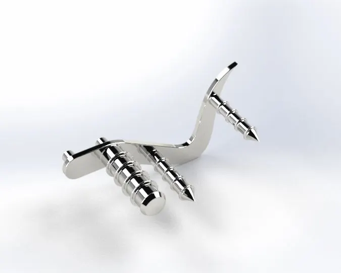
7. PEDAL:
- Pedal is an automobile machine component.
- It is used for keep the rider's foot on it while riding the brake.
- The pedal is placed in forward position of chopper.
- As well as legs of the rider can be fully expanded comfortably.
- The pedals also provide the enough grip to riders foot to avoid slipping.
SKETCH TOOLS:
- 3 Point arc
- Circle
- Spline
- Line
- Sketch fillet
FEATURES:
- Extruded boss
- Revolve
- Fillet
- Dome
- Champer
- Linear pattern
- Appearance
8. FRONT WHEEL:
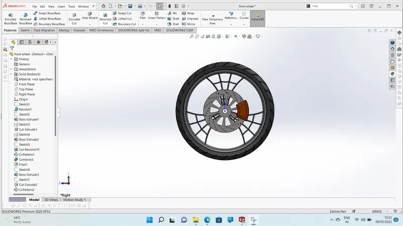
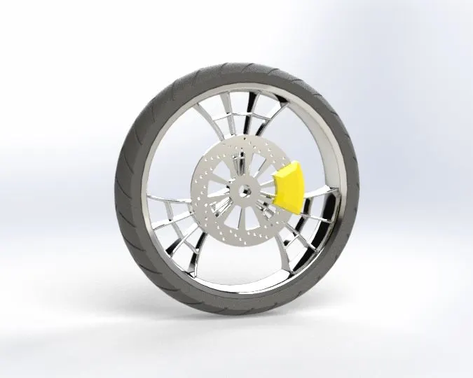
- The front wheel consists of rim, tire,disc brake,rotor & caliper.
- A front wheel is designed specially yo keep the front wheel of bike from turning out of place when being transported from one location to another.
- Tires are main contact surface to the ground.
- Tire portion of wheel contains thread like patterns which provides the grip to the road.
- Rim portion of the wheel have more strength & toughness to sustain the impact loads & fatigue loads.
- Front wheel of the chopper are always larger than tthe rear wheel.
- The front wheel in this American chopper has a diameter of 604 mm which is approximately 23.7 inches.
SKETCH TOOLS:
- 3 Point arc
- Lines
- Mid-point line
- Circle
- Sketch fillet
- Trim
- Extend
- 3 point centre rectangles
FEATURES:
- Revolve boss/base
- Extrude boss/base
- Extrude cut
- Revolve cut
- Circular pattern
- Combine
- Fillet
- Champer
- Appearance
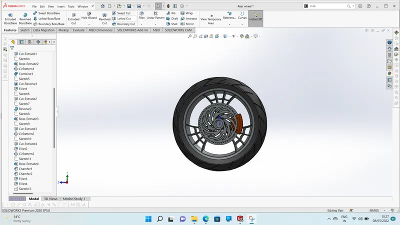
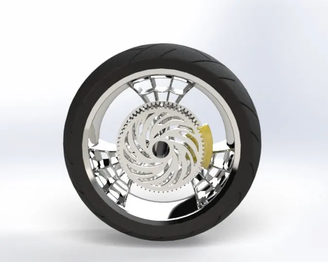
9.REAR WHEEL:
- The rear wheel consists of rim, tire,rotor, caliper & sprocket.
- Rear wheel of the chopper are generally smaller in diameter than front wheel.
- The rear wheel has connected with chain sprocket to drive the wheel by using transmission of engine.
- The rear wheel has a diameter of 484.5 mm which is approximately 19 inches.
SKETCH TOOLS:
- 3 Point arc
- Lines
- Splines
- Mid point line
- Circle
- Sketch fillet
- Trim
- Extend
- 3-point centre rectangles
FEATURES:
- Revolve boss/ base
- Extrude boss/base
- Extrude cut
- Revolve cut
- Circular pattern
- Combine
- Fillet
- Champer
- Appearance
10. FRONT FORKS:
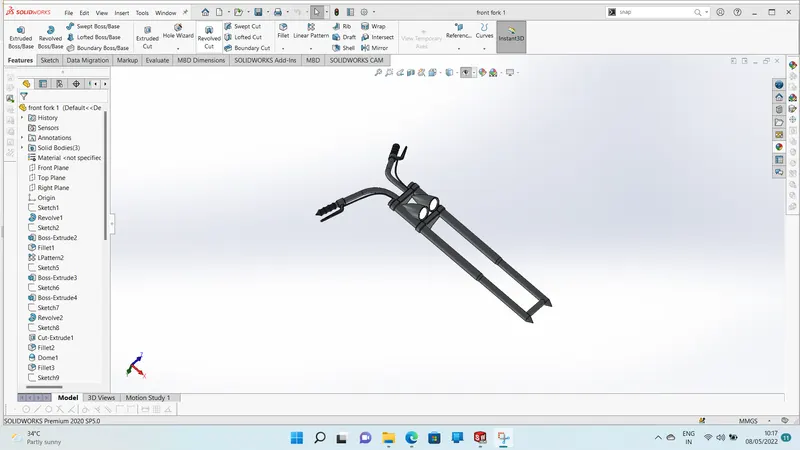
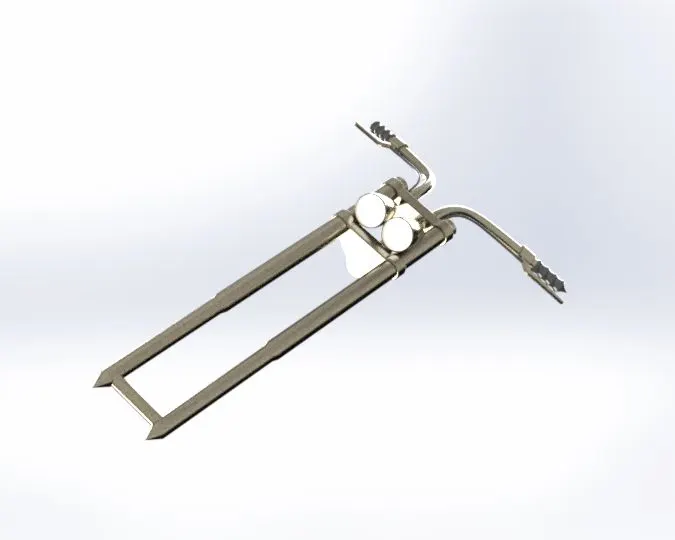
- It consists of handle bar, handle grip,triple clamp, brake lever, clutch lever, cables & axles.
- It is a component connects with front wheel of chopper and axle to its frame which is called telescopic forks.
- It acts as the suspension at the front of chopper.
- The front wheel is held by an axle &connected to the fork.
- It has two prongs that go around each side of the wheel.
- Front fork is used as a steering control to turn the chopper while on running.
SKETCH TOOLS:
- 3 Point arc
- Lines
- Splines
- Circle
- Trim
FEATURES:
- Revolve boss/base
- Extrude boss/base
- Linear pattern
- Extrude cut
- Revolve cut
- Dome
- Body move/copy
- Curves-projected
- Sweep
- Reference-geometry-planes
- Mirror
- Combine
- Fillet
- Champer
- Appearance
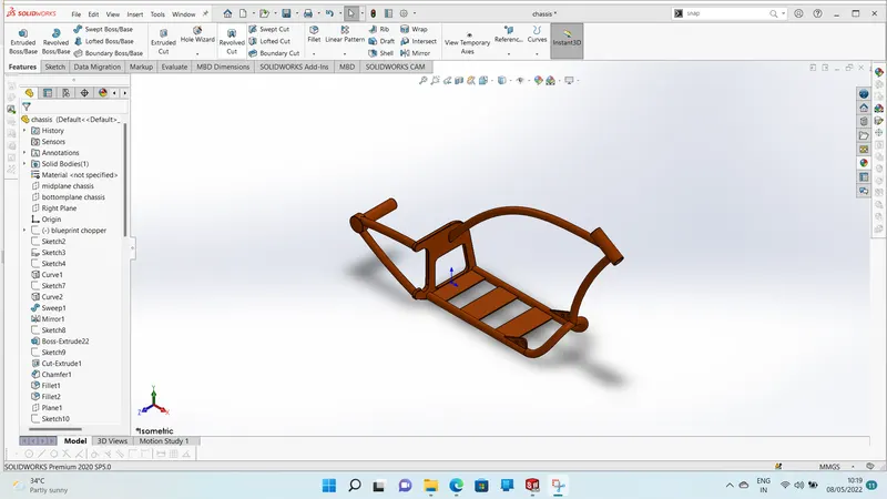
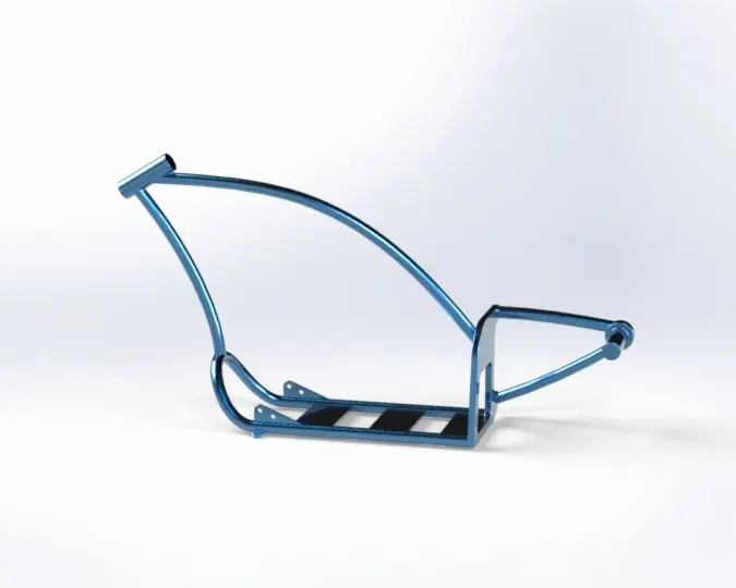
11. CHASSIS:
- Chassis is the backbone of the American chopper bike.
- Chassis component should be made up of high strength materials
- It held the all parts of the American chopper.
SKETCH TOOLS:
- Sketch picture
- Lines
- Splines
- Circle
- Trim
FEATURES:
- Extrude boss/base
- Extrude cut
- Revolve
- Dome
- Curves- projected
- Sweep
- Split
- Reference geometry-planes
- Mirror
- Combine
- Fillet
- Champer
- Appearance
12. ENGINE:
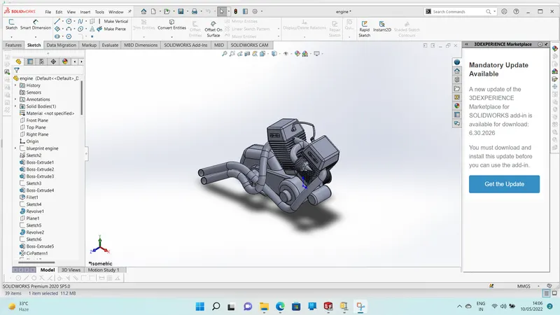
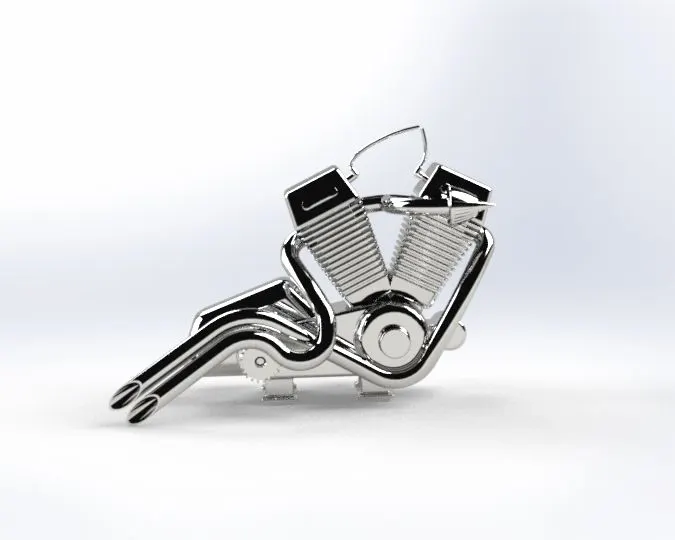
- Engine is the power of bike.
- Bike engines are typically two stroke or four stroke internal combustion engine.
- The consists of cylinder, pistons, connecting rod, crankshaft, aparkplug & engine valve arrangement.
- The American chopper bike has V-twin tyoe engine consists of external air filter & sparkplug for each cylinder, transmissin pulleys, air cooling fins, starter motor, front sprocket for chain drive , exhaust pipes & casing for sumps gear box.
SKETCH TOOLS:
- Sketch picture
- Lines
- Splines
- Circle
- Circular sketch pattern
- Construction line
- Center point rectangle
- 3 Point center rectangle
- Trim
FEATURES:
- Extrude boss/base
- Extrude cut
- Revolve
- Dome
- Curves-projected
- Composite - curves
- Sweep
- Split
- Reference geometry-planes
- Circular pattern
- Linear pattern
- Mirror
- Champer
- Appearance
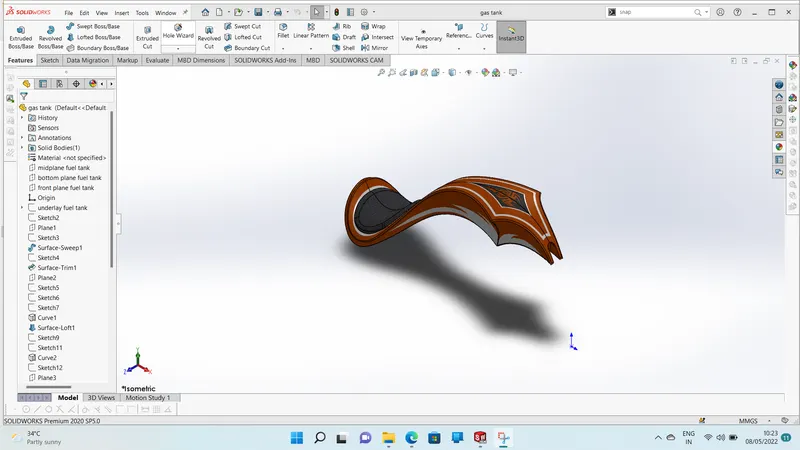
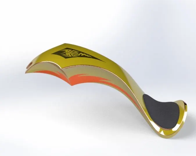
13. GAS TANK:
- A fuel tank is the safe storage component.
- Safety of the fuel is main criteria in designing the fuel tank.
- The term is typically applied to the part of the engine system in which the fuel is stored and propelled or released into an engine.
- The fuel tank of american chopper is made to house with seat & attached centrally to the chassis.
SKETCH TOOLS:
- Sketch picture
- Lines
- Splines
- Construction line
- Trim
FEATURES:
- Surface sweeep
- Surface loft
- Surface trim
- Boundary surface
- Surface knit
- Surface extrude
- Curves
- Projected curves
- Split line
- Sweep cut
- REeference geometry -planes
- Mirror
- Shell
- Fillet
- Appearance
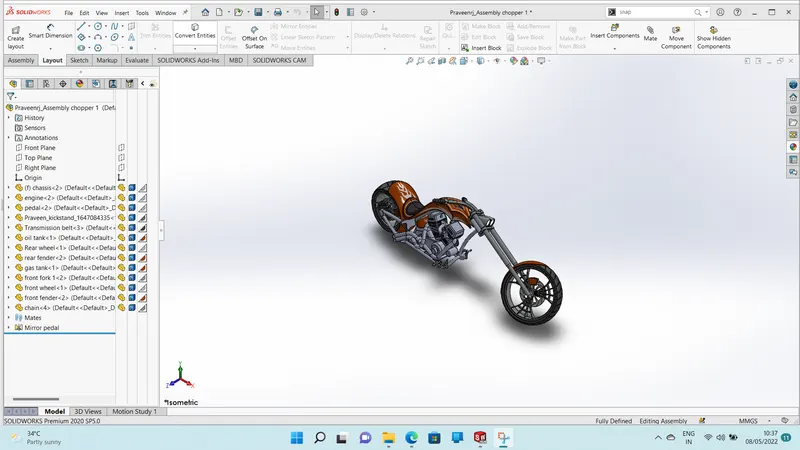
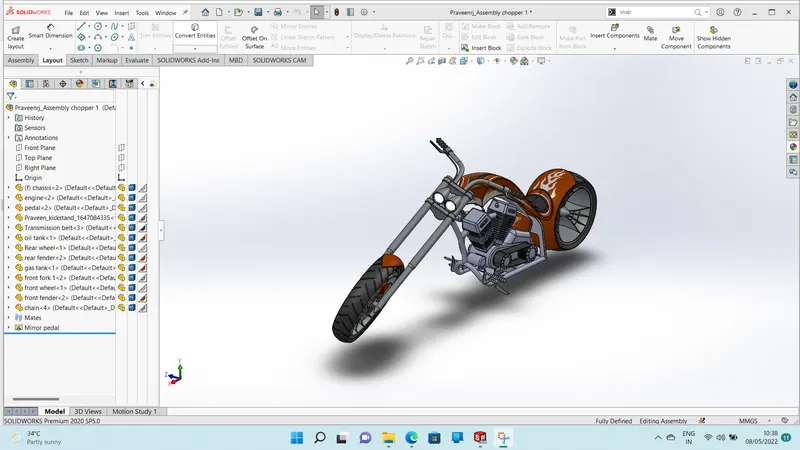
ASSEMBLY OF AMERICAN CHOPPER :
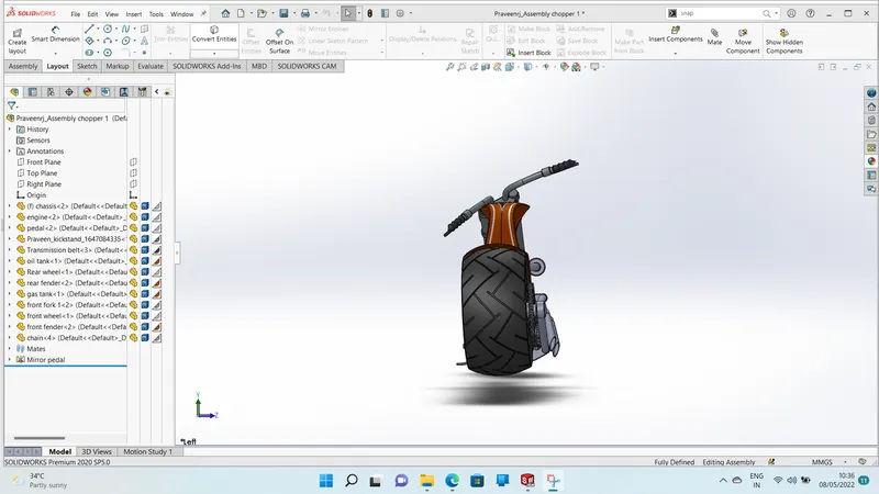
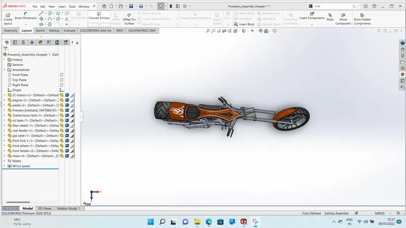
- Select the assembly options on the solidworks software.
- Open the all part files on the assembly files
- Apply the coincident relation for all assembly planes and all chassis planes
- Assembly the all part by using the mates
- Standard mates are
- Coincident
- Parallel
- Perpendicular
- Concentric
- Advanced mate is
- Width mate

PHOTORELISTIC RENDER:
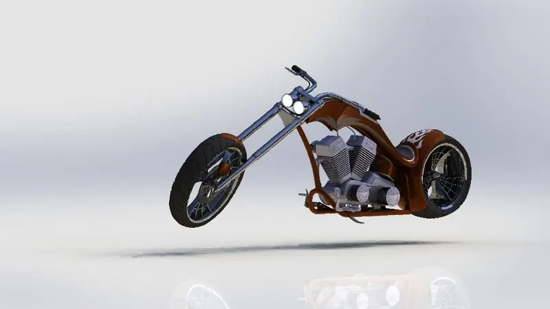
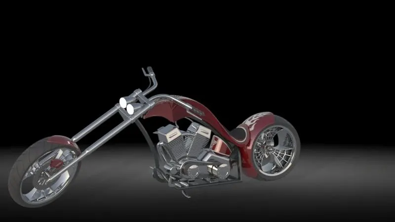
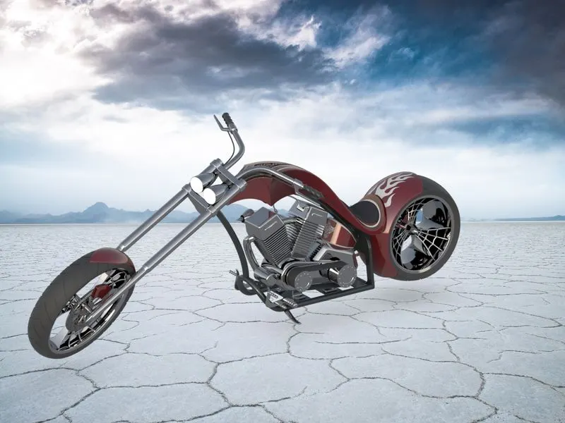
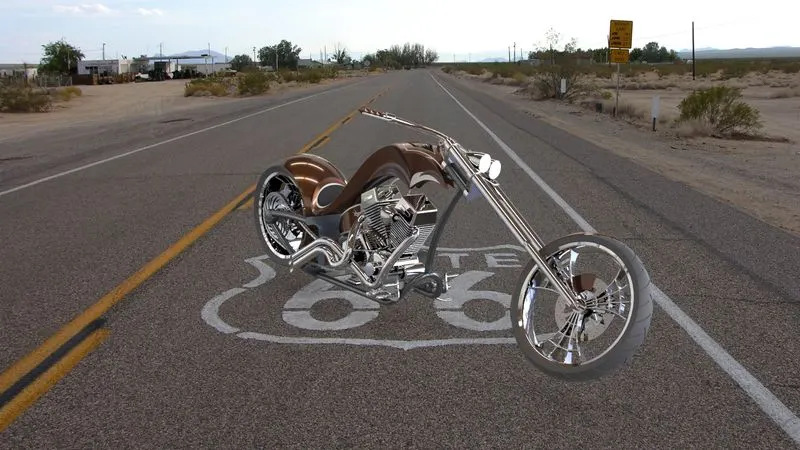
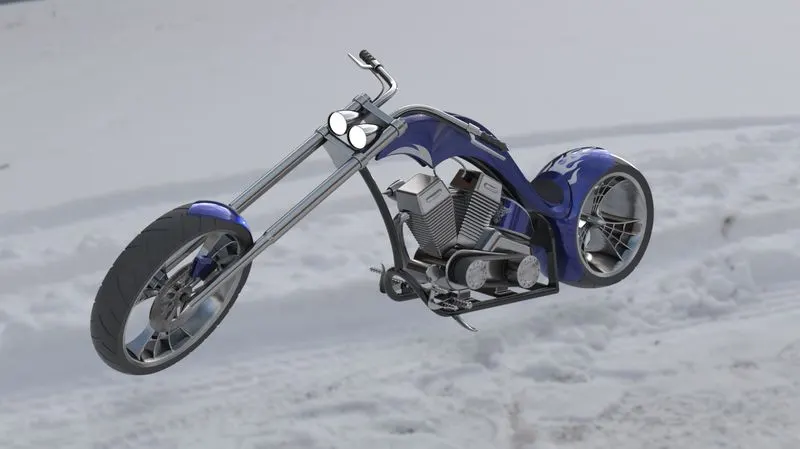
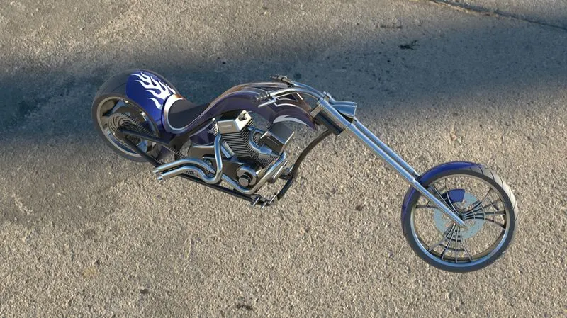
- Build the assembled chopper as a photorealistic render by using the apply of appearances, decals, scenes & camera views.
CONCLUSION:
- Design, assembly and photorealistic rendering using soliworks was successfully completed.
DESIGN AND ASSEMBLY OF AMERICAN CHOPPER
OBJECTIVE:
- To design and model the american chopper using solidworks.
- Modelling the each part of american chopper.
- Assembly all modeled parts to get the chopper.
- Rendering the american chopper by the apply of appearance and decals.
- Build the assembled chopper as a photorealistic render of environment.
INTRODUCTION:
- Solidworks is a mechanical 3D CAD ( computer-aided design) software.
- It helps to designing & modelling the components (or) parts.
- Modelling the complex structure of components by using the apply of solidworks tools, commands, features.
- It can also helps to render the parts.
DESIGN METHODOLOGY:
MODELED PARTS OF AMERICAN CHOPPER:
- TRANSMISSION BELT
- KICKSTAND (OR) SIDESTAND
- FRONT FENDER
- REAR FENDER
- CHAIN
- OIL TANK
- FRONT WHEEL
- REAR WHEEL
- FRONT FORK
- CHASSIS
- ENGINE
- GAS TANK
EXPLANATION OF FEATURES:
PLANE:
- To draw the section view of the parts.
- To draw the particular portion (or) side of part.
SKETCH:
- To draw the part by applying the command and smart dimensions at particular plane.
FILLET:
- It creates the round shapes at corner of the edge of part.
CHAMPER:
- It creates the sloping/tapered shape at corner of the edge.
CONVERT ENTITIES:
- It gives the same sketch profile on the same plane (or) other plane with same dimension value.
OFFSET ENTITIES:
- It creates the same sketch profile from selected model edges by specified distance.
MIRROR ENTITIES:
- When you create mirrored entities, apply a symmetric relation between each corresponding pair of sketch points.
SHELL:
- The shell tool creates hollows out the inside of the solid, leaving a shell of a specified wall thickness.
EXTRUDE BOSS/BASE:
- Extrude tool is used to extend the sketch in one or two direction with solid feature.
REVOLVED BOSS/BASE:
- It is used to create the revolved solid body sketch with reference of axis or lines.
EXTRUDE CUT:
- It is used to remove the materials from solid body in either one or two direction.
REVOLVE CUT:
- It is used to remove the materials from revolved solid body sketch in either one or two direction.
SWEPT BOSS/BASE:
- It creates the solid body around the sketch profile along an open & closed path.
LOFT:
- This feature creates a complex shape between the multiple profiles & guide curves.
DOME:
- It creates tangent to adjacent cylindrical & conical surfaces.
TRIM:
- It is used to remove the extra line of the surface.
PATTERN:
- It creates the number of sketch profiles through selected sketch along the reference path.
SPLIT:
- The split tool is used to project onto other surface or curved planar surfaces.
PROJECTED CURVE:
- Project the sketched curve on the model face & combines with another 2D curve to get the 3D curve.
APPEARANCE:
- By using this get the different look & apply the different appearances.
DECALS:
- By using this feature painted stickers to be applied on the model of chopper.
EXPLANATION OF PARTS:
1. TRANSMISSION BELT :
- It is a loop of flexible materials used to link two or more pulley.
- It transmits the power or motion without losing synchronisation.
- Forces are transmitted from the input pulley to the belt & then from the belt back to the output pulley.
- The transmission belt made using the matte rubber materials.
SKETCH TOOLS:
- 3 Point arc
- Line
- Circle
- Trim
- Offset entities
FEATURES:
- Extrude
- Fillet
- Appearance
2. KICKSTAND OR SIDESTAND:
- Kickstand or side stand is a mechanical component used to support the motorcycle in rest position.
- The kickstand is mounted on the chassis through mounting point.
- It has high tensile/compressive stress to withstand the load of the bike.
SKETCH TOOLS:
- Ellipse
- Spline
- Pierce
FEATURES:
- Loft
- Split
- Dome
- Extruded boss
- Extruded cut
- Fillet
- Appearance
3. FRONT FENDER:
- It is an automobile part or other vehicle body that frames wheel well.
- The primary purpose is to prevent sand, mud, rocks, liquids and other road spray being thrown into air by rotating tire.
- A fender is mounted over the wheel
- A front wheels require fender to provide mud & gravel protection on the rear side.
- The fender openings for the wheels well tend to be much larger than the diameter of the tires.
SKETCH TOOLS:
- 3 Point arc
- Offset entities
- Line
- Spline
FEATURES:
- Revolve
- Split
- Mirror entities
- Fillet
- Appearance
4. REAR FENDER:
- It is an automobile part or other vehicle body that frames wheel well.
- The primary purpose is to prevent sand, mud, rocks, liquids and other road spray being thrown into air by rotating tire.
- A fender is mounted on the wheel.
- The rear wheels require fender to provide mud & gravel protection on the front side.
- The fender openings for the wheels wells tend to be much larger than the diameter of tires.
SKETCH TOOLS:
- 3 Point arc
- Offset entities
- Line
- Spline
FEATURES:
- Revolve
- Split
- Shell
- Mirror entities
- Fillet
- Appearance
5. OIL TANK:
- Oil tank is a tank that holds the capacity of oil to cool the bike.
- The oil tank is located below the rear seat on the top of the gearbox.
- In the American chopper we have used the oil tank for engine lubrication & cooling.
SKETCH TOLS:
- 3 Point arc
- Line
FEATURES:
- Extruded boss/base
- Fillet
- Combine
- Shell
- Appearance
6. CHAIN:
- It is a way of transmitting mechanical power from one place to another.
- It is often used to convey power to the wheels of the bike.
- Chain pins are properly mating with sprocket without slip while run.
SKETCH TOOLS:
- 3 Point arc
- Centrepoint slots
- Circle
FEATURES:
- Extruded boss
- Make and save block
- Fillet
- Curve driven pattern
- Mirror
- Appearance
7. PEDAL:
- Pedal is an automobile machine component.
- It is used for keep the rider's foot on it while riding the brake.
- The pedal is placed in forward position of chopper.
- As well as legs of the rider can be fully expanded comfortably.
- The pedals also provide the enough grip to riders foot to avoid slipping.
SKETCH TOOLS:
- 3 Point arc
- Circle
- Spline
- Line
- Sketch fillet
FEATURES:
- Extruded boss
- Revolve
- Fillet
- Dome
- Champer
- Linear pattern
- Appearance
8. FRONT WHEEL:
- The front wheel consists of rim, tire,disc brake,rotor & caliper.
- A front wheel is designed specially yo keep the front wheel of bike from turning out of place when being transported from one location to another.
- Tires are main contact surface to the ground.
- Tire portion of wheel contains thread like patterns which provides the grip to the road.
- Rim portion of the wheel have more strength & toughness to sustain the impact loads & fatigue loads.
- Front wheel of the chopper are always larger than tthe rear wheel.
- The front wheel in this American chopper has a diameter of 604 mm which is approximately 23.7 inches.
SKETCH TOOLS:
- 3 Point arc
- Lines
- Mid-point line
- Circle
- Sketch fillet
- Trim
- Extend
- 3 point centre rectangles
FEATURES:
- Revolve boss/base
- Extrude boss/base
- Extrude cut
- Revolve cut
- Circular pattern
- Combine
- Fillet
- Champer
- Appearance
9.REAR WHEEL:
- The rear wheel consists of rim, tire,rotor, caliper & sprocket.
- Rear wheel of the chopper are generally smaller in diameter than front wheel.
- The rear wheel has connected with chain sprocket to drive the wheel by using transmission of engine.
- The rear wheel has a diameter of 484.5 mm which is approximately 19 inches.
SKETCH TOOLS:
- 3 Point arc
- Lines
- Splines
- Mid point line
- Circle
- Sketch fillet
- Trim
- Extend
- 3-point centre rectangles
FEATURES:
- Revolve boss/ base
- Extrude boss/base
- Extrude cut
- Revolve cut
- Circular pattern
- Combine
- Fillet
- Champer
- Appearance
10. FRONT FORKS:
- It consists of handle bar, handle grip,triple clamp, brake lever, clutch lever, cables & axles.
- It is a component connects with front wheel of chopper and axle to its frame which is called telescopic forks.
- It acts as the suspension at the front of chopper.
- The front wheel is held by an axle &connected to the fork.
- It has two prongs that go around each side of the wheel.
- Front fork is used as a steering control to turn the chopper while on running.
SKETCH TOOLS:
- 3 Point arc
- Lines
- Splines
- Circle
- Trim
FEATURES:
- Revolve boss/base
- Extrude boss/base
- Linear pattern
- Extrude cut
- Revolve cut
- Dome
- Body move/copy
- Curves-projected
- Sweep
- Reference-geometry-planes
- Mirror
- Combine
- Fillet
- Champer
- Appearance
11. CHASSIS:
- Chassis is the backbone of the American chopper bike.
- Chassis component should be made up of high strength materials
- It held the all parts of the American chopper.
SKETCH TOOLS:
- Sketch picture
- Lines
- Splines
- Circle
- Trim
FEATURES:
- Extrude boss/base
- Extrude cut
- Revolve
- Dome
- Curves- projected
- Sweep
- Split
- Reference geometry-planes
- Mirror
- Combine
- Fillet
- Champer
- Appearance
12. ENGINE:
- Engine is the power of bike.
- Bike engines are typically two stroke or four stroke internal combustion engine.
- The consists of cylinder, pistons, connecting rod, crankshaft, aparkplug & engine valve arrangement.
- The American chopper bike has V-twin tyoe engine consists of external air filter & sparkplug for each cylinder, transmissin pulleys, air cooling fins, starter motor, front sprocket for chain drive , exhaust pipes & casing for sumps gear box.
SKETCH TOOLS:
- Sketch picture
- Lines
- Splines
- Circle
- Circular sketch pattern
- Construction line
- Center point rectangle
- 3 Point center rectangle
- Trim
FEATURES:
- Extrude boss/base
- Extrude cut
- Revolve
- Dome
- Curves-projected
- Composite - curves
- Sweep
- Split
- Reference geometry-planes
- Circular pattern
- Linear pattern
- Mirror
- Champer
- Appearance
13. GAS TANK:
- A fuel tank is the safe storage component.
- Safety of the fuel is main criteria in designing the fuel tank.
- The term is typically applied to the part of the engine system in which the fuel is stored and propelled or released into an engine.
- The fuel tank of american chopper is made to house with seat & attached centrally to the chassis.
SKETCH TOOLS:
- Sketch picture
- Lines
- Splines
- Construction line
- Trim
FEATURES:
- Surface sweeep
- Surface loft
- Surface trim
- Boundary surface
- Surface knit
- Surface extrude
- Curves
- Projected curves
- Split line
- Sweep cut
- REeference geometry -planes
- Mirror
- Shell
- Fillet
- Appearance
ASSEMBLY OF AMERICAN CHOPPER :
- Select the assembly options on the solidworks software.
- Open the all part files on the assembly files
- Apply the coincident relation for all assembly planes and all chassis planes
- Assembly the all part by using the mates
- Standard mates are
- Coincident
- Parallel
- Perpendicular
- Concentric
- Advanced mate is
- Width mate
PHOTORELISTIC RENDER:
- Build the assembled chopper as a photorealistic render by using the apply of appearances, decals, scenes & camera views.
CONCLUSION:
- Design, assembly and photorealistic rendering using soliworks was successfully completed.
DESIGN AND ASSEMBLY OF AMERICAN CHOPPER
OBJECTIVE:
- To design and model the american chopper using solidworks.
- Modelling the each part of american chopper.
- Assembly all modeled parts to get the chopper.
- Rendering the american chopper by the apply of appearance and decals.
- Build the assembled chopper as a photorealistic render of environment.
INTRODUCTION:
- Solidworks is a mechanical 3D CAD ( computer-aided design) software.
- It helps to designing & modelling the components (or) parts.
- Modelling the complex structure of components by using the apply of solidworks tools, commands, features.
- It can also helps to render the parts.
DESIGN METHODOLOGY:
MODELED PARTS OF AMERICAN CHOPPER:
- TRANSMISSION BELT
- KICKSTAND (OR) SIDESTAND
- FRONT FENDER
- REAR FENDER
- CHAIN
- OIL TANK
- FRONT WHEEL
- REAR WHEEL
- FRONT FORK
- CHASSIS
- ENGINE
- GAS TANK
EXPLANATION OF FEATURES:
PLANE:
- To draw the section view of the parts.
- To draw the particular portion (or) side of part.
SKETCH:
- To draw the part by applying the command and smart dimensions at particular plane.
FILLET:
- It creates the round shapes at corner of the edge of part.
CHAMPER:
- It creates the sloping/tapered shape at corner of the edge.
CONVERT ENTITIES:
- It gives the same sketch profile on the same plane (or) other plane with same dimension value.
OFFSET ENTITIES:
- It creates the same sketch profile from selected model edges by specified distance.
MIRROR ENTITIES:
- When you create mirrored entities, apply a symmetric relation between each corresponding pair of sketch points.
SHELL:
- The shell tool creates hollows out the inside of the solid, leaving a shell of a specified wall thickness.
EXTRUDE BOSS/BASE:
- Extrude tool is used to extend the sketch in one or two direction with solid feature.
REVOLVED BOSS/BASE:
- It is used to create the revolved solid body sketch with reference of axis or lines.
EXTRUDE CUT:
- It is used to remove the materials from solid body in either one or two direction.
REVOLVE CUT:
- It is used to remove the materials from revolved solid body sketch in either one or two direction.
SWEPT BOSS/BASE:
- It creates the solid body around the sketch profile along an open & closed path.
LOFT:
- This feature creates a complex shape between the multiple profiles & guide curves.
DOME:
- It creates tangent to adjacent cylindrical & conical surfaces.
TRIM:
- It is used to remove the extra line of the surface.
PATTERN:
- It creates the number of sketch profiles through selected sketch along the reference path.
SPLIT:
- The split tool is used to project onto other surface or curved planar surfaces.
PROJECTED CURVE:
- Project the sketched curve on the model face & combines with another 2D curve to get the 3D curve.
APPEARANCE:
- By using this get the different look & apply the different appearances.
DECALS:
- By using this feature painted stickers to be applied on the model of chopper.
EXPLANATION OF PARTS:
1. TRANSMISSION BELT :
- It is a loop of flexible materials used to link two or more pulley.
- It transmits the power or motion without losing synchronisation.
- Forces are transmitted from the input pulley to the belt & then from the belt back to the output pulley.
- The transmission belt made using the matte rubber materials.
SKETCH TOOLS:
- 3 Point arc
- Line
- Circle
- Trim
- Offset entities
FEATURES:
- Extrude
- Fillet
- Appearance
2. KICKSTAND OR SIDESTAND:
- Kickstand or side stand is a mechanical component used to support the motorcycle in rest position.
- The kickstand is mounted on the chassis through mounting point.
- It has high tensile/compressive stress to withstand the load of the bike.
SKETCH TOOLS:
- Ellipse
- Spline
- Pierce
FEATURES:
- Loft
- Split
- Dome
- Extruded boss
- Extruded cut
- Fillet
- Appearance
3. FRONT FENDER:
- It is an automobile part or other vehicle body that frames wheel well.
- The primary purpose is to prevent sand, mud, rocks, liquids and other road spray being thrown into air by rotating tire.
- A fender is mounted over the wheel
- A front wheels require fender to provide mud & gravel protection on the rear side.
- The fender openings for the wheels well tend to be much larger than the diameter of the tires.
SKETCH TOOLS:
- 3 Point arc
- Offset entities
- Line
- Spline
FEATURES:
- Revolve
- Split
- Mirror entities
- Fillet
- Appearance
4. REAR FENDER:
- It is an automobile part or other vehicle body that frames wheel well.
- The primary purpose is to prevent sand, mud, rocks, liquids and other road spray being thrown into air by rotating tire.
- A fender is mounted on the wheel.
- The rear wheels require fender to provide mud & gravel protection on the front side.
- The fender openings for the wheels wells tend to be much larger than the diameter of tires.
SKETCH TOOLS:
- 3 Point arc
- Offset entities
- Line
- Spline
FEATURES:
- Revolve
- Split
- Shell
- Mirror entities
- Fillet
- Appearance
5. OIL TANK:
- Oil tank is a tank that holds the capacity of oil to cool the bike.
- The oil tank is located below the rear seat on the top of the gearbox.
- In the American chopper we have used the oil tank for engine lubrication & cooling.
SKETCH TOLS:
- 3 Point arc
- Line
FEATURES:
- Extruded boss/base
- Fillet
- Combine
- Shell
- Appearance
6. CHAIN:
- It is a way of transmitting mechanical power from one place to another.
- It is often used to convey power to the wheels of the bike.
- Chain pins are properly mating with sprocket without slip while run.
SKETCH TOOLS:
- 3 Point arc
- Centrepoint slots
- Circle
FEATURES:
- Extruded boss
- Make and save block
- Fillet
- Curve driven pattern
- Mirror
- Appearance
7. PEDAL:
- Pedal is an automobile machine component.
- It is used for keep the rider's foot on it while riding the brake.
- The pedal is placed in forward position of chopper.
- As well as legs of the rider can be fully expanded comfortably.
- The pedals also provide the enough grip to riders foot to avoid slipping.
SKETCH TOOLS:
- 3 Point arc
- Circle
- Spline
- Line
- Sketch fillet
FEATURES:
- Extruded boss
- Revolve
- Fillet
- Dome
- Champer
- Linear pattern
- Appearance
8. FRONT WHEEL:
- The front wheel consists of rim, tire,disc brake,rotor & caliper.
- A front wheel is designed specially yo keep the front wheel of bike from turning out of place when being transported from one location to another.
- Tires are main contact surface to the ground.
- Tire portion of wheel contains thread like patterns which provides the grip to the road.
- Rim portion of the wheel have more strength & toughness to sustain the impact loads & fatigue loads.
- Front wheel of the chopper are always larger than tthe rear wheel.
- The front wheel in this American chopper has a diameter of 604 mm which is approximately 23.7 inches.
SKETCH TOOLS:
- 3 Point arc
- Lines
- Mid-point line
- Circle
- Sketch fillet
- Trim
- Extend
- 3 point centre rectangles
FEATURES:
- Revolve boss/base
- Extrude boss/base
- Extrude cut
- Revolve cut
- Circular pattern
- Combine
- Fillet
- Champer
- Appearance
9.REAR WHEEL:
- The rear wheel consists of rim, tire,rotor, caliper & sprocket.
- Rear wheel of the chopper are generally smaller in diameter than front wheel.
- The rear wheel has connected with chain sprocket to drive the wheel by using transmission of engine.
- The rear wheel has a diameter of 484.5 mm which is approximately 19 inches.
SKETCH TOOLS:
- 3 Point arc
- Lines
- Splines
- Mid point line
- Circle
- Sketch fillet
- Trim
- Extend
- 3-point centre rectangles
FEATURES:
- Revolve boss/ base
- Extrude boss/base
- Extrude cut
- Revolve cut
- Circular pattern
- Combine
- Fillet
- Champer
- Appearance
10. FRONT FORKS:
- It consists of handle bar, handle grip,triple clamp, brake lever, clutch lever, cables & axles.
- It is a component connects with front wheel of chopper and axle to its frame which is called telescopic forks.
- It acts as the suspension at the front of chopper.
- The front wheel is held by an axle &connected to the fork.
- It has two prongs that go around each side of the wheel.
- Front fork is used as a steering control to turn the chopper while on running.
SKETCH TOOLS:
- 3 Point arc
- Lines
- Splines
- Circle
- Trim
FEATURES:
- Revolve boss/base
- Extrude boss/base
- Linear pattern
- Extrude cut
- Revolve cut
- Dome
- Body move/copy
- Curves-projected
- Sweep
- Reference-geometry-planes
- Mirror
- Combine
- Fillet
- Champer
- Appearance
11. CHASSIS:
- Chassis is the backbone of the American chopper bike.
- Chassis component should be made up of high strength materials
- It held the all parts of the American chopper.
SKETCH TOOLS:
- Sketch picture
- Lines
- Splines
- Circle
- Trim
FEATURES:
- Extrude boss/base
- Extrude cut
- Revolve
- Dome
- Curves- projected
- Sweep
- Split
- Reference geometry-planes
- Mirror
- Combine
- Fillet
- Champer
- Appearance
12. ENGINE:
- Engine is the power of bike.
- Bike engines are typically two stroke or four stroke internal combustion engine.
- The consists of cylinder, pistons, connecting rod, crankshaft, aparkplug & engine valve arrangement.
- The American chopper bike has V-twin tyoe engine consists of external air filter & sparkplug for each cylinder, transmissin pulleys, air cooling fins, starter motor, front sprocket for chain drive , exhaust pipes & casing for sumps gear box.
SKETCH TOOLS:
- Sketch picture
- Lines
- Splines
- Circle
- Circular sketch pattern
- Construction line
- Center point rectangle
- 3 Point center rectangle
- Trim
FEATURES:
- Extrude boss/base
- Extrude cut
- Revolve
- Dome
- Curves-projected
- Composite - curves
- Sweep
- Split
- Reference geometry-planes
- Circular pattern
- Linear pattern
- Mirror
- Champer
- Appearance
13. GAS TANK:
- A fuel tank is the safe storage component.
- Safety of the fuel is main criteria in designing the fuel tank.
- The term is typically applied to the part of the engine system in which the fuel is stored and propelled or released into an engine.
- The fuel tank of american chopper is made to house with seat & attached centrally to the chassis.
SKETCH TOOLS:
- Sketch picture
- Lines
- Splines
- Construction line
- Trim
FEATURES:
- Surface sweeep
- Surface loft
- Surface trim
- Boundary surface
- Surface knit
- Surface extrude
- Curves
- Projected curves
- Split line
- Sweep cut
- REeference geometry -planes
- Mirror
- Shell
- Fillet
- Appearance
ASSEMBLY OF AMERICAN CHOPPER :
- Select the assembly options on the solidworks software.
- Open the all part files on the assembly files
- Apply the coincident relation for all assembly planes and all chassis planes
- Assembly the all part by using the mates
- Standard mates are
- Coincident
- Parallel
- Perpendicular
- Concentric
- Advanced mate is
- Width mate
PHOTORELISTIC RENDER:
- Build the assembled chopper as a photorealistic render by using the apply of appearances, decals, scenes & camera views.
CONCLUSION:
- Design, assembly and photorealistic rendering using soliworks was successfully completed.
DESIGN AND ASSEMBLY OF AMERICAN CHOPPER
OBJECTIVE:
- To design and model the american chopper using solidworks.
- Modelling the each part of american chopper.
- Assembly all modeled parts to get the chopper.
- Rendering the american chopper by the apply of appearance and decals.
- Build the assembled chopper as a photorealistic render of environment.
INTRODUCTION:
- Solidworks is a mechanical 3D CAD ( computer-aided design) software.
- It helps to designing & modelling the components (or) parts.
- Modelling the complex structure of components by using the apply of solidworks tools, commands, features.
- It can also helps to render the parts.
DESIGN METHODOLOGY:
MODELED PARTS OF AMERICAN CHOPPER:
- TRANSMISSION BELT
- KICKSTAND (OR) SIDESTAND
- FRONT FENDER
- REAR FENDER
- CHAIN
- OIL TANK
- FRONT WHEEL
- REAR WHEEL
- FRONT FORK
- CHASSIS
- ENGINE
- GAS TANK
EXPLANATION OF FEATURES:
PLANE:
- To draw the section view of the parts.
- To draw the particular portion (or) side of part.
SKETCH:
- To draw the part by applying the command and smart dimensions at particular plane.
FILLET:
- It creates the round shapes at corner of the edge of part.
CHAMPER:
- It creates the sloping/tapered shape at corner of the edge.
CONVERT ENTITIES:
- It gives the same sketch profile on the same plane (or) other plane with same dimension value.
OFFSET ENTITIES:
- It creates the same sketch profile from selected model edges by specified distance.
MIRROR ENTITIES:
- When you create mirrored entities, apply a symmetric relation between each corresponding pair of sketch points.
SHELL:
- The shell tool creates hollows out the inside of the solid, leaving a shell of a specified wall thickness.
EXTRUDE BOSS/BASE:
- Extrude tool is used to extend the sketch in one or two direction with solid feature.
REVOLVED BOSS/BASE:
- It is used to create the revolved solid body sketch with reference of axis or lines.
EXTRUDE CUT:
- It is used to remove the materials from solid body in either one or two direction.
REVOLVE CUT:
- It is used to remove the materials from revolved solid body sketch in either one or two direction.
SWEPT BOSS/BASE:
- It creates the solid body around the sketch profile along an open & closed path.
LOFT:
- This feature creates a complex shape between the multiple profiles & guide curves.
DOME:
- It creates tangent to adjacent cylindrical & conical surfaces.
TRIM:
- It is used to remove the extra line of the surface.
PATTERN:
- It creates the number of sketch profiles through selected sketch along the reference path.
SPLIT:
- The split tool is used to project onto other surface or curved planar surfaces.
PROJECTED CURVE:
- Project the sketched curve on the model face & combines with another 2D curve to get the 3D curve.
APPEARANCE:
- By using this get the different look & apply the different appearances.
DECALS:
- By using this feature painted stickers to be applied on the model of chopper.
EXPLANATION OF PARTS:
1. TRANSMISSION BELT :
- It is a loop of flexible materials used to link two or more pulley.
- It transmits the power or motion without losing synchronisation.
- Forces are transmitted from the input pulley to the belt & then from the belt back to the output pulley.
- The transmission belt made using the matte rubber materials.
SKETCH TOOLS:
- 3 Point arc
- Line
- Circle
- Trim
- Offset entities
FEATURES:
- Extrude
- Fillet
- Appearance
2. KICKSTAND OR SIDESTAND:
- Kickstand or side stand is a mechanical component used to support the motorcycle in rest position.
- The kickstand is mounted on the chassis through mounting point.
- It has high tensile/compressive stress to withstand the load of the bike.
SKETCH TOOLS:
- Ellipse
- Spline
- Pierce
FEATURES:
- Loft
- Split
- Dome
- Extruded boss
- Extruded cut
- Fillet
- Appearance
3. FRONT FENDER:
- It is an automobile part or other vehicle body that frames wheel well.
- The primary purpose is to prevent sand, mud, rocks, liquids and other road spray being thrown into air by rotating tire.
- A fender is mounted over the wheel
- A front wheels require fender to provide mud & gravel protection on the rear side.
- The fender openings for the wheels well tend to be much larger than the diameter of the tires.
SKETCH TOOLS:
- 3 Point arc
- Offset entities
- Line
- Spline
FEATURES:
- Revolve
- Split
- Mirror entities
- Fillet
- Appearance
4. REAR FENDER:
- It is an automobile part or other vehicle body that frames wheel well.
- The primary purpose is to prevent sand, mud, rocks, liquids and other road spray being thrown into air by rotating tire.
- A fender is mounted on the wheel.
- The rear wheels require fender to provide mud & gravel protection on the front side.
- The fender openings for the wheels wells tend to be much larger than the diameter of tires.
SKETCH TOOLS:
- 3 Point arc
- Offset entities
- Line
- Spline
FEATURES:
- Revolve
- Split
- Shell
- Mirror entities
- Fillet
- Appearance
5. OIL TANK:
- Oil tank is a tank that holds the capacity of oil to cool the bike.
- The oil tank is located below the rear seat on the top of the gearbox.
- In the American chopper we have used the oil tank for engine lubrication & cooling.
SKETCH TOLS:
- 3 Point arc
- Line
FEATURES:
- Extruded boss/base
- Fillet
- Combine
- Shell
- Appearance
6. CHAIN:
- It is a way of transmitting mechanical power from one place to another.
- It is often used to convey power to the wheels of the bike.
- Chain pins are properly mating with sprocket without slip while run.
SKETCH TOOLS:
- 3 Point arc
- Centrepoint slots
- Circle
FEATURES:
- Extruded boss
- Make and save block
- Fillet
- Curve driven pattern
- Mirror
- Appearance
7. PEDAL:
- Pedal is an automobile machine component.
- It is used for keep the rider's foot on it while riding the brake.
- The pedal is placed in forward position of chopper.
- As well as legs of the rider can be fully expanded comfortably.
- The pedals also provide the enough grip to riders foot to avoid slipping.
SKETCH TOOLS:
- 3 Point arc
- Circle
- Spline
- Line
- Sketch fillet
FEATURES:
- Extruded boss
- Revolve
- Fillet
- Dome
- Champer
- Linear pattern
- Appearance
8. FRONT WHEEL:
- The front wheel consists of rim, tire,disc brake,rotor & caliper.
- A front wheel is designed specially yo keep the front wheel of bike from turning out of place when being transported from one location to another.
- Tires are main contact surface to the ground.
- Tire portion of wheel contains thread like patterns which provides the grip to the road.
- Rim portion of the wheel have more strength & toughness to sustain the impact loads & fatigue loads.
- Front wheel of the chopper are always larger than tthe rear wheel.
- The front wheel in this American chopper has a diameter of 604 mm which is approximately 23.7 inches.
SKETCH TOOLS:
- 3 Point arc
- Lines
- Mid-point line
- Circle
- Sketch fillet
- Trim
- Extend
- 3 point centre rectangles
FEATURES:
- Revolve boss/base
- Extrude boss/base
- Extrude cut
- Revolve cut
- Circular pattern
- Combine
- Fillet
- Champer
- Appearance
9.REAR WHEEL:
- The rear wheel consists of rim, tire,rotor, caliper & sprocket.
- Rear wheel of the chopper are generally smaller in diameter than front wheel.
- The rear wheel has connected with chain sprocket to drive the wheel by using transmission of engine.
- The rear wheel has a diameter of 484.5 mm which is approximately 19 inches.
SKETCH TOOLS:
- 3 Point arc
- Lines
- Splines
- Mid point line
- Circle
- Sketch fillet
- Trim
- Extend
- 3-point centre rectangles
FEATURES:
- Revolve boss/ base
- Extrude boss/base
- Extrude cut
- Revolve cut
- Circular pattern
- Combine
- Fillet
- Champer
- Appearance
10. FRONT FORKS:
- It consists of handle bar, handle grip,triple clamp, brake lever, clutch lever, cables & axles.
- It is a component connects with front wheel of chopper and axle to its frame which is called telescopic forks.
- It acts as the suspension at the front of chopper.
- The front wheel is held by an axle &connected to the fork.
- It has two prongs that go around each side of the wheel.
- Front fork is used as a steering control to turn the chopper while on running.
SKETCH TOOLS:
- 3 Point arc
- Lines
- Splines
- Circle
- Trim
FEATURES:
- Revolve boss/base
- Extrude boss/base
- Linear pattern
- Extrude cut
- Revolve cut
- Dome
- Body move/copy
- Curves-projected
- Sweep
- Reference-geometry-planes
- Mirror
- Combine
- Fillet
- Champer
- Appearance
11. CHASSIS:
- Chassis is the backbone of the American chopper bike.
- Chassis component should be made up of high strength materials
- It held the all parts of the American chopper.
SKETCH TOOLS:
- Sketch picture
- Lines
- Splines
- Circle
- Trim
FEATURES:
- Extrude boss/base
- Extrude cut
- Revolve
- Dome
- Curves- projected
- Sweep
- Split
- Reference geometry-planes
- Mirror
- Combine
- Fillet
- Champer
- Appearance
12. ENGINE:
- Engine is the power of bike.
- Bike engines are typically two stroke or four stroke internal combustion engine.
- The consists of cylinder, pistons, connecting rod, crankshaft, aparkplug & engine valve arrangement.
- The American chopper bike has V-twin tyoe engine consists of external air filter & sparkplug for each cylinder, transmissin pulleys, air cooling fins, starter motor, front sprocket for chain drive , exhaust pipes & casing for sumps gear box.
SKETCH TOOLS:
- Sketch picture
- Lines
- Splines
- Circle
- Circular sketch pattern
- Construction line
- Center point rectangle
- 3 Point center rectangle
- Trim
FEATURES:
- Extrude boss/base
- Extrude cut
- Revolve
- Dome
- Curves-projected
- Composite - curves
- Sweep
- Split
- Reference geometry-planes
- Circular pattern
- Linear pattern
- Mirror
- Champer
- Appearance
13. GAS TANK:
- A fuel tank is the safe storage component.
- Safety of the fuel is main criteria in designing the fuel tank.
- The term is typically applied to the part of the engine system in which the fuel is stored and propelled or released into an engine.
- The fuel tank of american chopper is made to house with seat & attached centrally to the chassis.
SKETCH TOOLS:
- Sketch picture
- Lines
- Splines
- Construction line
- Trim
FEATURES:
- Surface sweeep
- Surface loft
- Surface trim
- Boundary surface
- Surface knit
- Surface extrude
- Curves
- Projected curves
- Split line
- Sweep cut
- REeference geometry -planes
- Mirror
- Shell
- Fillet
- Appearance
ASSEMBLY OF AMERICAN CHOPPER :
- Select the assembly options on the solidworks software.
- Open the all part files on the assembly files
- Apply the coincident relation for all assembly planes and all chassis planes
- Assembly the all part by using the mates
- Standard mates are
- Coincident
- Parallel
- Perpendicular
- Concentric
- Advanced mate is
- Width mate
PHOTORELISTIC RENDER:
- Build the assembled chopper as a photorealistic render by using the apply of appearances, decals, scenes & camera views.
CONCLUSION:
- Design, assembly and photorealistic rendering using soliworks was successfully completed.
DESIGN AND ASSEMBLY OF AMERICAN CHOPPER
OBJECTIVE:
- To design and model the american chopper using solidworks.
- Modelling the each part of american chopper.
- Assembly all modeled parts to get the chopper.
- Rendering the american chopper by the apply of appearance and decals.
- Build the assembled chopper as a photorealistic render of environment.
INTRODUCTION:
- Solidworks is a mechanical 3D CAD ( computer-aided design) software.
- It helps to designing & modelling the components (or) parts.
- Modelling the complex structure of components by using the apply of solidworks tools, commands, features.
- It can also helps to render the parts.
DESIGN METHODOLOGY:
MODELED PARTS OF AMERICAN CHOPPER:
- TRANSMISSION BELT
- KICKSTAND (OR) SIDESTAND
- FRONT FENDER
- REAR FENDER
- CHAIN
- OIL TANK
- FRONT WHEEL
- REAR WHEEL
- FRONT FORK
- CHASSIS
- ENGINE
- GAS TANK
EXPLANATION OF FEATURES:
PLANE:
- To draw the section view of the parts.
- To draw the particular portion (or) side of part.
SKETCH:
- To draw the part by applying the command and smart dimensions at particular plane.
FILLET:
- It creates the round shapes at corner of the edge of part.
CHAMPER:
- It creates the sloping/tapered shape at corner of the edge.
CONVERT ENTITIES:
- It gives the same sketch profile on the same plane (or) other plane with same dimension value.
OFFSET ENTITIES:
- It creates the same sketch profile from selected model edges by specified distance.
MIRROR ENTITIES:
- When you create mirrored entities, apply a symmetric relation between each corresponding pair of sketch points.
SHELL:
- The shell tool creates hollows out the inside of the solid, leaving a shell of a specified wall thickness.
EXTRUDE BOSS/BASE:
- Extrude tool is used to extend the sketch in one or two direction with solid feature.
REVOLVED BOSS/BASE:
- It is used to create the revolved solid body sketch with reference of axis or lines.
EXTRUDE CUT:
- It is used to remove the materials from solid body in either one or two direction.
REVOLVE CUT:
- It is used to remove the materials from revolved solid body sketch in either one or two direction.
SWEPT BOSS/BASE:
- It creates the solid body around the sketch profile along an open & closed path.
LOFT:
- This feature creates a complex shape between the multiple profiles & guide curves.
DOME:
- It creates tangent to adjacent cylindrical & conical surfaces.
TRIM:
- It is used to remove the extra line of the surface.
PATTERN:
- It creates the number of sketch profiles through selected sketch along the reference path.
SPLIT:
- The split tool is used to project onto other surface or curved planar surfaces.
PROJECTED CURVE:
- Project the sketched curve on the model face & combines with another 2D curve to get the 3D curve.
APPEARANCE:
- By using this get the different look & apply the different appearances.
DECALS:
- By using this feature painted stickers to be applied on the model of chopper.
EXPLANATION OF PARTS:
1. TRANSMISSION BELT :
- It is a loop of flexible materials used to link two or more pulley.
- It transmits the power or motion without losing synchronisation.
- Forces are transmitted from the input pulley to the belt & then from the belt back to the output pulley.
- The transmission belt made using the matte rubber materials.
SKETCH TOOLS:
- 3 Point arc
- Line
- Circle
- Trim
- Offset entities
FEATURES:
- Extrude
- Fillet
- Appearance
2. KICKSTAND OR SIDESTAND:
- Kickstand or side stand is a mechanical component used to support the motorcycle in rest position.
- The kickstand is mounted on the chassis through mounting point.
- It has high tensile/compressive stress to withstand the load of the bike.
SKETCH TOOLS:
- Ellipse
- Spline
- Pierce
FEATURES:
- Loft
- Split
- Dome
- Extruded boss
- Extruded cut
- Fillet
- Appearance
3. FRONT FENDER:
- It is an automobile part or other vehicle body that frames wheel well.
- The primary purpose is to prevent sand, mud, rocks, liquids and other road spray being thrown into air by rotating tire.
- A fender is mounted over the wheel
- A front wheels require fender to provide mud & gravel protection on the rear side.
- The fender openings for the wheels well tend to be much larger than the diameter of the tires.
SKETCH TOOLS:
- 3 Point arc
- Offset entities
- Line
- Spline
FEATURES:
- Revolve
- Split
- Mirror entities
- Fillet
- Appearance
4. REAR FENDER:
- It is an automobile part or other vehicle body that frames wheel well.
- The primary purpose is to prevent sand, mud, rocks, liquids and other road spray being thrown into air by rotating tire.
- A fender is mounted on the wheel.
- The rear wheels require fender to provide mud & gravel protection on the front side.
- The fender openings for the wheels wells tend to be much larger than the diameter of tires.
SKETCH TOOLS:
- 3 Point arc
- Offset entities
- Line
- Spline
FEATURES:
- Revolve
- Split
- Shell
- Mirror entities
- Fillet
- Appearance
5. OIL TANK:
- Oil tank is a tank that holds the capacity of oil to cool the bike.
- The oil tank is located below the rear seat on the top of the gearbox.
- In the American chopper we have used the oil tank for engine lubrication & cooling.
SKETCH TOLS:
- 3 Point arc
- Line
FEATURES:
- Extruded boss/base
- Fillet
- Combine
- Shell
- Appearance
6. CHAIN:
- It is a way of transmitting mechanical power from one place to another.
- It is often used to convey power to the wheels of the bike.
- Chain pins are properly mating with sprocket without slip while run.
SKETCH TOOLS:
- 3 Point arc
- Centrepoint slots
- Circle
FEATURES:
- Extruded boss
- Make and save block
- Fillet
- Curve driven pattern
- Mirror
- Appearance
7. PEDAL:
- Pedal is an automobile machine component.
- It is used for keep the rider's foot on it while riding the brake.
- The pedal is placed in forward position of chopper.
- As well as legs of the rider can be fully expanded comfortably.
- The pedals also provide the enough grip to riders foot to avoid slipping.
SKETCH TOOLS:
- 3 Point arc
- Circle
- Spline
- Line
- Sketch fillet
FEATURES:
- Extruded boss
- Revolve
- Fillet
- Dome
- Champer
- Linear pattern
- Appearance
8. FRONT WHEEL:
- The front wheel consists of rim, tire,disc brake,rotor & caliper.
- A front wheel is designed specially yo keep the front wheel of bike from turning out of place when being transported from one location to another.
- Tires are main contact surface to the ground.
- Tire portion of wheel contains thread like patterns which provides the grip to the road.
- Rim portion of the wheel have more strength & toughness to sustain the impact loads & fatigue loads.
- Front wheel of the chopper are always larger than tthe rear wheel.
- The front wheel in this American chopper has a diameter of 604 mm which is approximately 23.7 inches.
SKETCH TOOLS:
- 3 Point arc
- Lines
- Mid-point line
- Circle
- Sketch fillet
- Trim
- Extend
- 3 point centre rectangles
FEATURES:
- Revolve boss/base
- Extrude boss/base
- Extrude cut
- Revolve cut
- Circular pattern
- Combine
- Fillet
- Champer
- Appearance
9.REAR WHEEL:
- The rear wheel consists of rim, tire,rotor, caliper & sprocket.
- Rear wheel of the chopper are generally smaller in diameter than front wheel.
- The rear wheel has connected with chain sprocket to drive the wheel by using transmission of engine.
- The rear wheel has a diameter of 484.5 mm which is approximately 19 inches.
SKETCH TOOLS:
- 3 Point arc
- Lines
- Splines
- Mid point line
- Circle
- Sketch fillet
- Trim
- Extend
- 3-point centre rectangles
FEATURES:
- Revolve boss/ base
- Extrude boss/base
- Extrude cut
- Revolve cut
- Circular pattern
- Combine
- Fillet
- Champer
- Appearance
10. FRONT FORKS:
- It consists of handle bar, handle grip,triple clamp, brake lever, clutch lever, cables & axles.
- It is a component connects with front wheel of chopper and axle to its frame which is called telescopic forks.
- It acts as the suspension at the front of chopper.
- The front wheel is held by an axle &connected to the fork.
- It has two prongs that go around each side of the wheel.
- Front fork is used as a steering control to turn the chopper while on running.
SKETCH TOOLS:
- 3 Point arc
- Lines
- Splines
- Circle
- Trim
FEATURES:
- Revolve boss/base
- Extrude boss/base
- Linear pattern
- Extrude cut
- Revolve cut
- Dome
- Body move/copy
- Curves-projected
- Sweep
- Reference-geometry-planes
- Mirror
- Combine
- Fillet
- Champer
- Appearance
11. CHASSIS:
- Chassis is the backbone of the American chopper bike.
- Chassis component should be made up of high strength materials
- It held the all parts of the American chopper.
SKETCH TOOLS:
- Sketch picture
- Lines
- Splines
- Circle
- Trim
FEATURES:
- Extrude boss/base
- Extrude cut
- Revolve
- Dome
- Curves- projected
- Sweep
- Split
- Reference geometry-planes
- Mirror
- Combine
- Fillet
- Champer
- Appearance
12. ENGINE:
- Engine is the power of bike.
- Bike engines are typically two stroke or four stroke internal combustion engine.
- The consists of cylinder, pistons, connecting rod, crankshaft, aparkplug & engine valve arrangement.
- The American chopper bike has V-twin tyoe engine consists of external air filter & sparkplug for each cylinder, transmissin pulleys, air cooling fins, starter motor, front sprocket for chain drive , exhaust pipes & casing for sumps gear box.
SKETCH TOOLS:
- Sketch picture
- Lines
- Splines
- Circle
- Circular sketch pattern
- Construction line
- Center point rectangle
- 3 Point center rectangle
- Trim
FEATURES:
- Extrude boss/base
- Extrude cut
- Revolve
- Dome
- Curves-projected
- Composite - curves
- Sweep
- Split
- Reference geometry-planes
- Circular pattern
- Linear pattern
- Mirror
- Champer
- Appearance
13. GAS TANK:
- A fuel tank is the safe storage component.
- Safety of the fuel is main criteria in designing the fuel tank.
- The term is typically applied to the part of the engine system in which the fuel is stored and propelled or released into an engine.
- The fuel tank of american chopper is made to house with seat & attached centrally to the chassis.
SKETCH TOOLS:
- Sketch picture
- Lines
- Splines
- Construction line
- Trim
FEATURES:
- Surface sweeep
- Surface loft
- Surface trim
- Boundary surface
- Surface knit
- Surface extrude
- Curves
- Projected curves
- Split line
- Sweep cut
- REeference geometry -planes
- Mirror
- Shell
- Fillet
- Appearance
ASSEMBLY OF AMERICAN CHOPPER :
- Select the assembly options on the solidworks software.
- Open the all part files on the assembly files
- Apply the coincident relation for all assembly planes and all chassis planes
- Assembly the all part by using the mates
- Standard mates are
- Coincident
- Parallel
- Perpendicular
- Concentric
- Advanced mate is
- Width mate
PHOTORELISTIC RENDER:
- Build the assembled chopper as a photorealistic render by using the apply of appearances, decals, scenes & camera views.
CONCLUSION:
- Design, assembly and photorealistic rendering using soliworks was successfully completed.
DESIGN AND ASSEMBLY OF AMERICAN CHOPPER
OBJECTIVE:
- To design and model the american chopper using solidworks.
- Modelling the each part of american chopper.
- Assembly all modeled parts to get the chopper.
- Rendering the american chopper by the apply of appearance and decals.
- Build the assembled chopper as a photorealistic render of environment.
INTRODUCTION:
- Solidworks is a mechanical 3D CAD ( computer-aided design) software.
- It helps to designing & modelling the components (or) parts.
- Modelling the complex structure of components by using the apply of solidworks tools, commands, features.
- It can also helps to render the parts.
DESIGN METHODOLOGY:
MODELED PARTS OF AMERICAN CHOPPER:
- TRANSMISSION BELT
- KICKSTAND (OR) SIDESTAND
- FRONT FENDER
- REAR FENDER
- CHAIN
- OIL TANK
- FRONT WHEEL
- REAR WHEEL
- FRONT FORK
- CHASSIS
- ENGINE
- GAS TANK
EXPLANATION OF FEATURES:
PLANE:
- To draw the section view of the parts.
- To draw the particular portion (or) side of part.
SKETCH:
- To draw the part by applying the command and smart dimensions at particular plane.
FILLET:
- It creates the round shapes at corner of the edge of part.
CHAMPER:
- It creates the sloping/tapered shape at corner of the edge.
CONVERT ENTITIES:
- It gives the same sketch profile on the same plane (or) other plane with same dimension value.
OFFSET ENTITIES:
- It creates the same sketch profile from selected model edges by specified distance.
MIRROR ENTITIES:
- When you create mirrored entities, apply a symmetric relation between each corresponding pair of sketch points.
SHELL:
- The shell tool creates hollows out the inside of the solid, leaving a shell of a specified wall thickness.
EXTRUDE BOSS/BASE:
- Extrude tool is used to extend the sketch in one or two direction with solid feature.
REVOLVED BOSS/BASE:
- It is used to create the revolved solid body sketch with reference of axis or lines.
EXTRUDE CUT:
- It is used to remove the materials from solid body in either one or two direction.
REVOLVE CUT:
- It is used to remove the materials from revolved solid body sketch in either one or two direction.
SWEPT BOSS/BASE:
- It creates the solid body around the sketch profile along an open & closed path.
LOFT:
- This feature creates a complex shape between the multiple profiles & guide curves.
DOME:
- It creates tangent to adjacent cylindrical & conical surfaces.
TRIM:
- It is used to remove the extra line of the surface.
PATTERN:
- It creates the number of sketch profiles through selected sketch along the reference path.
SPLIT:
- The split tool is used to project onto other surface or curved planar surfaces.
PROJECTED CURVE:
- Project the sketched curve on the model face & combines with another 2D curve to get the 3D curve.
APPEARANCE:
- By using this get the different look & apply the different appearances.
DECALS:
- By using this feature painted stickers to be applied on the model of chopper.
EXPLANATION OF PARTS:
1. TRANSMISSION BELT :
- It is a loop of flexible materials used to link two or more pulley.
- It transmits the power or motion without losing synchronisation.
- Forces are transmitted from the input pulley to the belt & then from the belt back to the output pulley.
- The transmission belt made using the matte rubber materials.
SKETCH TOOLS:
- 3 Point arc
- Line
- Circle
- Trim
- Offset entities
FEATURES:
- Extrude
- Fillet
- Appearance
2. KICKSTAND OR SIDESTAND:
- Kickstand or side stand is a mechanical component used to support the motorcycle in rest position.
- The kickstand is mounted on the chassis through mounting point.
- It has high tensile/compressive stress to withstand the load of the bike.
SKETCH TOOLS:
- Ellipse
- Spline
- Pierce
FEATURES:
- Loft
- Split
- Dome
- Extruded boss
- Extruded cut
- Fillet
- Appearance
3. FRONT FENDER:
- It is an automobile part or other vehicle body that frames wheel well.
- The primary purpose is to prevent sand, mud, rocks, liquids and other road spray being thrown into air by rotating tire.
- A fender is mounted over the wheel
- A front wheels require fender to provide mud & gravel protection on the rear side.
- The fender openings for the wheels well tend to be much larger than the diameter of the tires.
SKETCH TOOLS:
- 3 Point arc
- Offset entities
- Line
- Spline
FEATURES:
- Revolve
- Split
- Mirror entities
- Fillet
- Appearance
4. REAR FENDER:
- It is an automobile part or other vehicle body that frames wheel well.
- The primary purpose is to prevent sand, mud, rocks, liquids and other road spray being thrown into air by rotating tire.
- A fender is mounted on the wheel.
- The rear wheels require fender to provide mud & gravel protection on the front side.
- The fender openings for the wheels wells tend to be much larger than the diameter of tires.
SKETCH TOOLS:
- 3 Point arc
- Offset entities
- Line
- Spline
FEATURES:
- Revolve
- Split
- Shell
- Mirror entities
- Fillet
- Appearance
5. OIL TANK:
- Oil tank is a tank that holds the capacity of oil to cool the bike.
- The oil tank is located below the rear seat on the top of the gearbox.
- In the American chopper we have used the oil tank for engine lubrication & cooling.
SKETCH TOLS:
- 3 Point arc
- Line
FEATURES:
- Extruded boss/base
- Fillet
- Combine
- Shell
- Appearance
6. CHAIN:
- It is a way of transmitting mechanical power from one place to another.
- It is often used to convey power to the wheels of the bike.
- Chain pins are properly mating with sprocket without slip while run.
SKETCH TOOLS:
- 3 Point arc
- Centrepoint slots
- Circle
FEATURES:
- Extruded boss
- Make and save block
- Fillet
- Curve driven pattern
- Mirror
- Appearance
7. PEDAL:
- Pedal is an automobile machine component.
- It is used for keep the rider's foot on it while riding the brake.
- The pedal is placed in forward position of chopper.
- As well as legs of the rider can be fully expanded comfortably.
- The pedals also provide the enough grip to riders foot to avoid slipping.
SKETCH TOOLS:
- 3 Point arc
- Circle
- Spline
- Line
- Sketch fillet
FEATURES:
- Extruded boss
- Revolve
- Fillet
- Dome
- Champer
- Linear pattern
- Appearance
8. FRONT WHEEL:
- The front wheel consists of rim, tire,disc brake,rotor & caliper.
- A front wheel is designed specially yo keep the front wheel of bike from turning out of place when being transported from one location to another.
- Tires are main contact surface to the ground.
- Tire portion of wheel contains thread like patterns which provides the grip to the road.
- Rim portion of the wheel have more strength & toughness to sustain the impact loads & fatigue loads.
- Front wheel of the chopper are always larger than tthe rear wheel.
- The front wheel in this American chopper has a diameter of 604 mm which is approximately 23.7 inches.
SKETCH TOOLS:
- 3 Point arc
- Lines
- Mid-point line
- Circle
- Sketch fillet
- Trim
- Extend
- 3 point centre rectangles
FEATURES:
- Revolve boss/base
- Extrude boss/base
- Extrude cut
- Revolve cut
- Circular pattern
- Combine
- Fillet
- Champer
- Appearance
9.REAR WHEEL:
- The rear wheel consists of rim, tire,rotor, caliper & sprocket.
- Rear wheel of the chopper are generally smaller in diameter than front wheel.
- The rear wheel has connected with chain sprocket to drive the wheel by using transmission of engine.
- The rear wheel has a diameter of 484.5 mm which is approximately 19 inches.
SKETCH TOOLS:
- 3 Point arc
- Lines
- Splines
- Mid point line
- Circle
- Sketch fillet
- Trim
- Extend
- 3-point centre rectangles
FEATURES:
- Revolve boss/ base
- Extrude boss/base
- Extrude cut
- Revolve cut
- Circular pattern
- Combine
- Fillet
- Champer
- Appearance
10. FRONT FORKS:
- It consists of handle bar, handle grip,triple clamp, brake lever, clutch lever, cables & axles.
- It is a component connects with front wheel of chopper and axle to its frame which is called telescopic forks.
- It acts as the suspension at the front of chopper.
- The front wheel is held by an axle &connected to the fork.
- It has two prongs that go around each side of the wheel.
- Front fork is used as a steering control to turn the chopper while on running.
SKETCH TOOLS:
- 3 Point arc
- Lines
- Splines
- Circle
- Trim
FEATURES:
- Revolve boss/base
- Extrude boss/base
- Linear pattern
- Extrude cut
- Revolve cut
- Dome
- Body move/copy
- Curves-projected
- Sweep
- Reference-geometry-planes
- Mirror
- Combine
- Fillet
- Champer
- Appearance
11. CHASSIS:
- Chassis is the backbone of the American chopper bike.
- Chassis component should be made up of high strength materials
- It held the all parts of the American chopper.
SKETCH TOOLS:
- Sketch picture
- Lines
- Splines
- Circle
- Trim
FEATURES:
- Extrude boss/base
- Extrude cut
- Revolve
- Dome
- Curves- projected
- Sweep
- Split
- Reference geometry-planes
- Mirror
- Combine
- Fillet
- Champer
- Appearance
12. ENGINE:
- Engine is the power of bike.
- Bike engines are typically two stroke or four stroke internal combustion engine.
- The consists of cylinder, pistons, connecting rod, crankshaft, aparkplug & engine valve arrangement.
- The American chopper bike has V-twin tyoe engine consists of external air filter & sparkplug for each cylinder, transmissin pulleys, air cooling fins, starter motor, front sprocket for chain drive , exhaust pipes & casing for sumps gear box.
SKETCH TOOLS:
- Sketch picture
- Lines
- Splines
- Circle
- Circular sketch pattern
- Construction line
- Center point rectangle
- 3 Point center rectangle
- Trim
FEATURES:
- Extrude boss/base
- Extrude cut
- Revolve
- Dome
- Curves-projected
- Composite - curves
- Sweep
- Split
- Reference geometry-planes
- Circular pattern
- Linear pattern
- Mirror
- Champer
- Appearance
13. GAS TANK:
- A fuel tank is the safe storage component.
- Safety of the fuel is main criteria in designing the fuel tank.
- The term is typically applied to the part of the engine system in which the fuel is stored and propelled or released into an engine.
- The fuel tank of american chopper is made to house with seat & attached centrally to the chassis.
SKETCH TOOLS:
- Sketch picture
- Lines
- Splines
- Construction line
- Trim
FEATURES:
- Surface sweeep
- Surface loft
- Surface trim
- Boundary surface
- Surface knit
- Surface extrude
- Curves
- Projected curves
- Split line
- Sweep cut
- REeference geometry -planes
- Mirror
- Shell
- Fillet
- Appearance
ASSEMBLY OF AMERICAN CHOPPER :
- Select the assembly options on the solidworks software.
- Open the all part files on the assembly files
- Apply the coincident relation for all assembly planes and all chassis planes
- Assembly the all part by using the mates
- Standard mates are
- Coincident
- Parallel
- Perpendicular
- Concentric
- Advanced mate is
- Width mate
PHOTORELISTIC RENDER:
- Build the assembled chopper as a photorealistic render by using the apply of appearances, decals, scenes & camera views.
CONCLUSION:
- Design, assembly and photorealistic rendering using soliworks was successfully completed.
https://drive.google.com/file/d/1OocmJQfrtOLiWsQuMqV6WzWqwOQqLDUO/view?usp=sharing