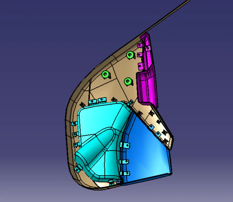
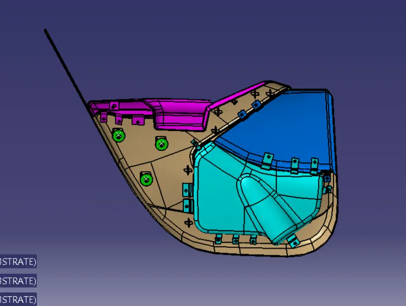
Week 11 - Final project
AIM:
To design and development of vehicle interior door trim using Catia V5 with given class A surface along with Master section. Also create the Side Attachment features as per design rules.
OBJECTIVE:
- To create thickened part using master section for reference
- To create the mounting features as per design guidelines in the industry and with master sections
- To perform Draft analysis & Tooling analysis
INTRODUCTION:
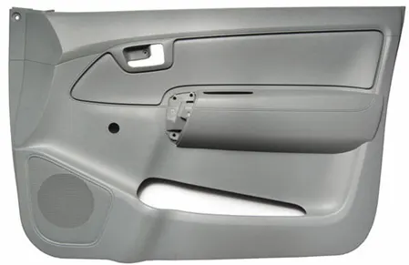
The door panel is the interface between the interior of the car and the inner workings of the door. Generally the door panel is divided into parts for easy designing like arm rest, map pocket, lower substrate. These require one of the toughest requirement among the interior parts of the car. This should be designed to with stand the load while being less than 2mm in thickness and also to protect the occupants during collisions.
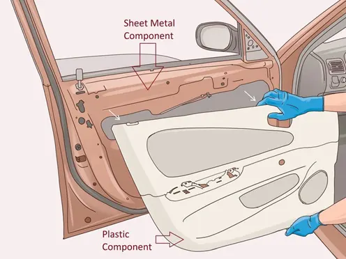
The door currently has an inner full-width panel consisting of electronic windows, a central locking system, and speakers. These panels typically consist of a foamed core covered with either textiles or plastics.
METHODOLGY:-
DOOR ARM REST:-
CLASS A SURFACE:-It is a surface that is provided by the styling team.
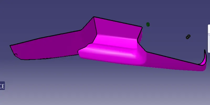
CLASS B SURFACE:-It is a surface that is created by offsetting the class A surface to 3 mm and doing required required modification i.e. the irregularities comes after offsetting the class A surface.
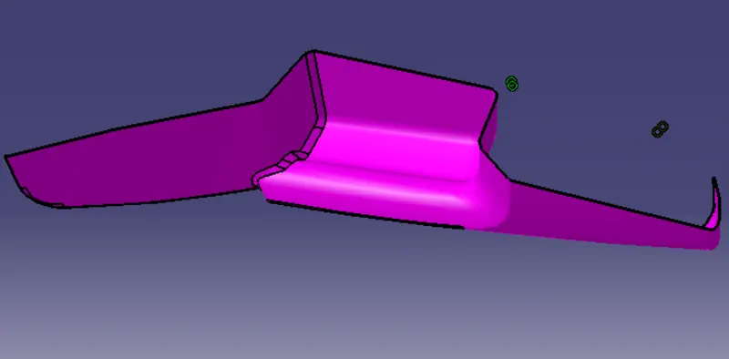
LEATHER SPACING WHICH IS SHOWN IN THE MASTER SECTION:-
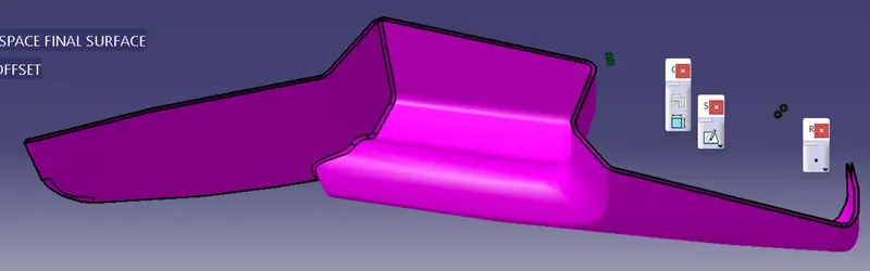
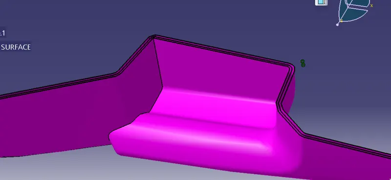
FINAL CLASS A,B, AND LEATHER SPACEING OFFSET:-
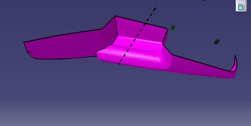
TOOLING AXIS:-
Unable to rotate class A surface as some assembly comtraint have bee provided so the tooling axis I created using surface extracted method .
-Frst of all a check the quality of class A surface.
-Look at all the direction through which the tool can move easily .
-I just extracted the class A flat surface created a point and a line simply.
CLASS C SURFACE:-
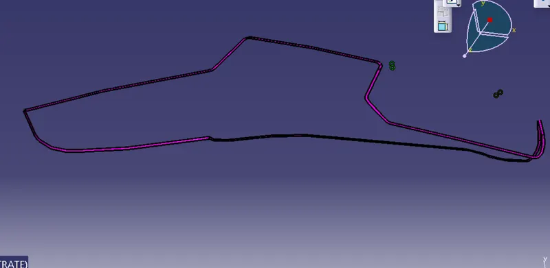
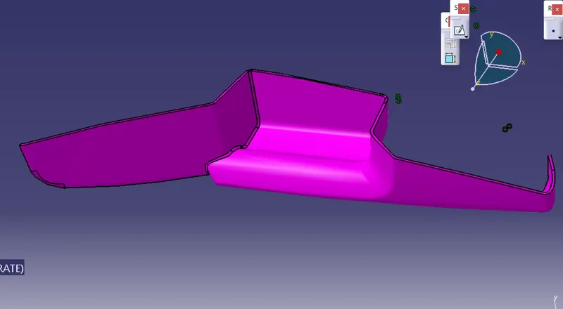
CLASS C SURFACE:
- For the creation of class B surface first the boundary of the class A surface is extracted using multiple extract feature
- After the sweep option is used to create the sweep along the tooling axis direction.
B-side engineering features:-
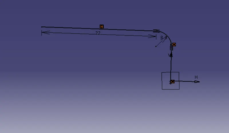
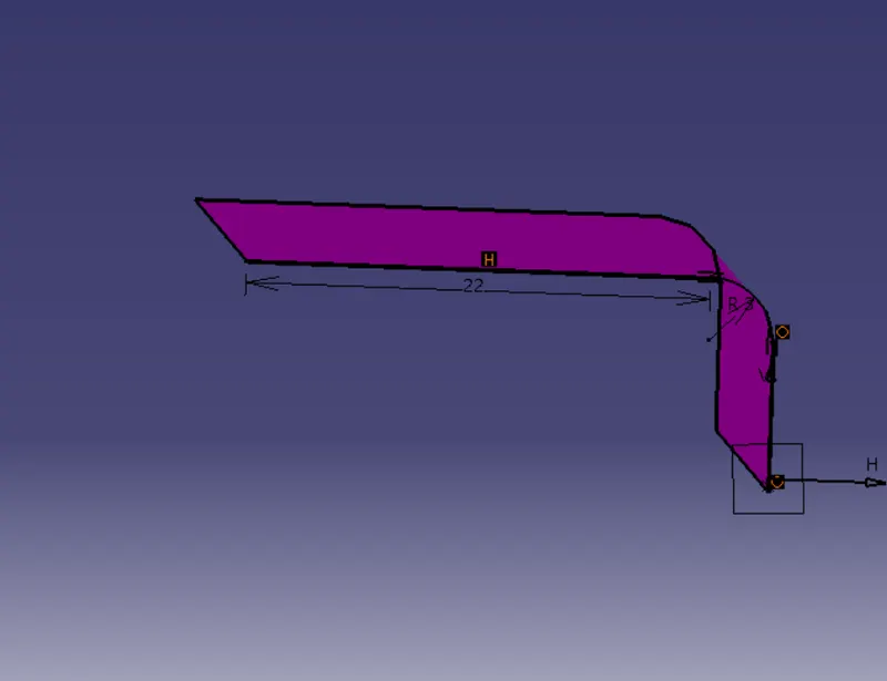
FLANGE-
DRAFT ANALYSIS:-
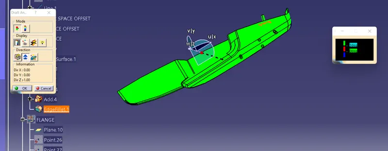
We do perform the draft analysis check for class A surface before we make solid and creation of B-side features. Initially I align the compass to the tooling axis and I gave a 3deg draft angle for the green colour in the colour bar. If the surface is highlighted in green colour the draft angle is given properly for class A surface. If the class A surface is not highlighted fully in green colour, that might be the reason for the draft angle of the class A surface.
FINAL BODY DRAFT ANALYSIS
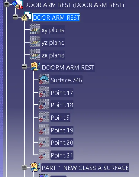
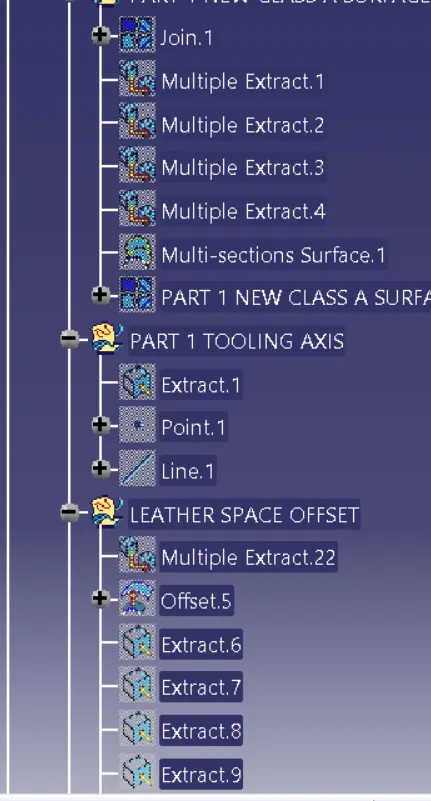
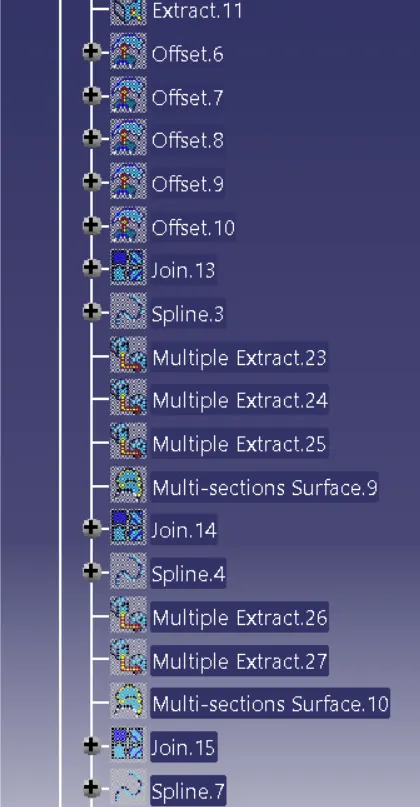
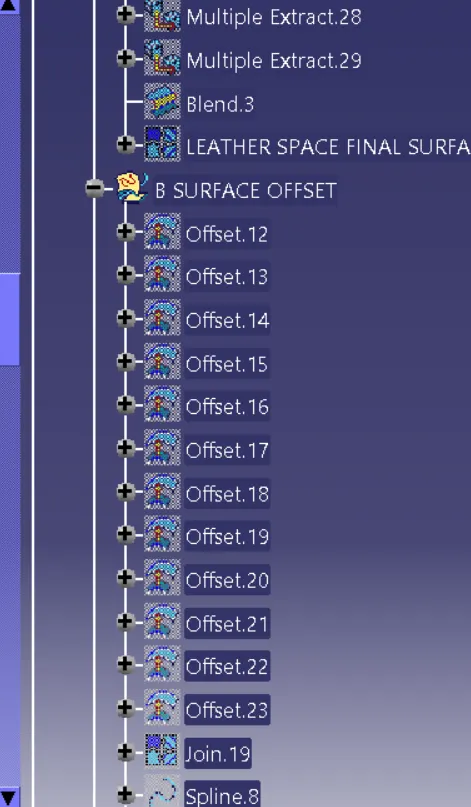
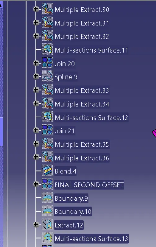
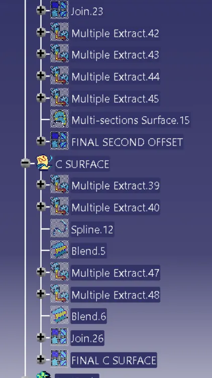
FEATURE TREE:-
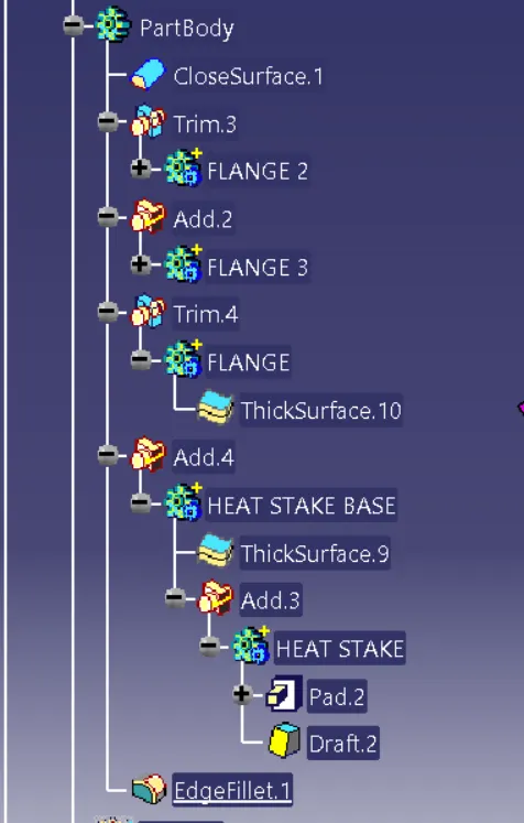
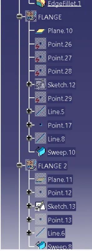
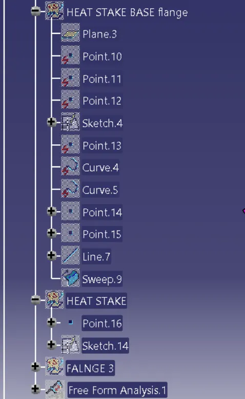
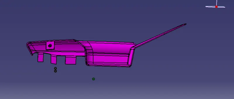
DIFFERENT VIEWS:-
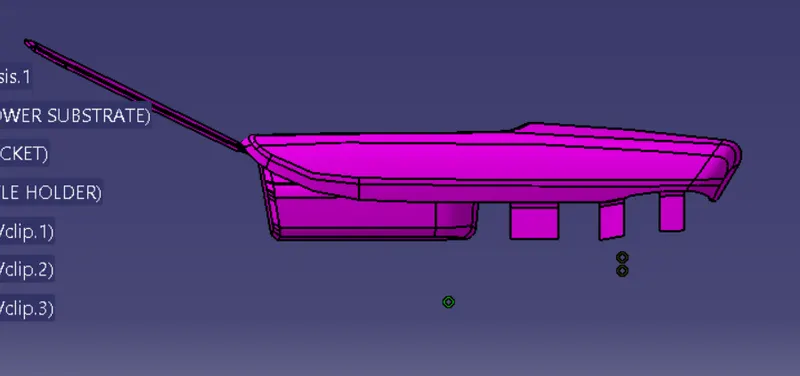
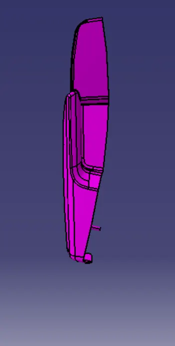
LOWER SUBSTRATE:-
CLASS A:-It is a surface that is provided by the styling team.
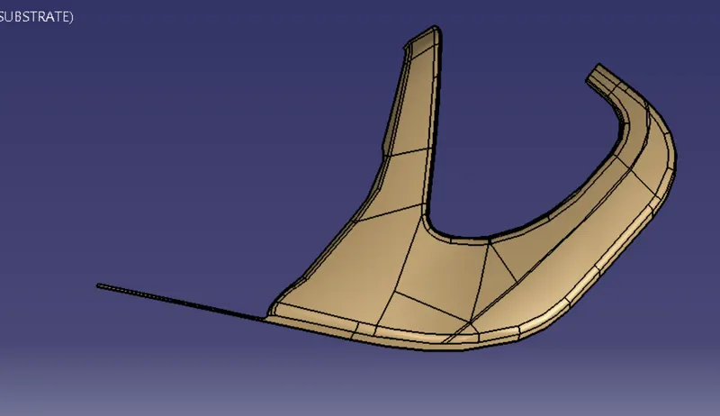
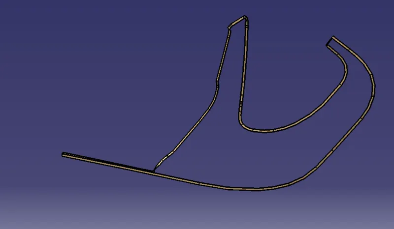
CLASS B SURFACE:-It is a surface that is created by offsetting the class A surface to 3 mm and doing required required modification i.e. the irregularities comes after offsetting the class A surface.
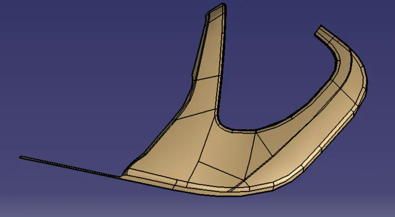
CLASS-C SURFACE:-
- For the creation of class B surface first the boundary of the class A surface is extracted using multiple extract feature
- After the sweep option is used to create the sweep along the tooling axis direction.
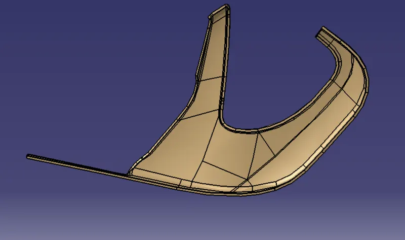
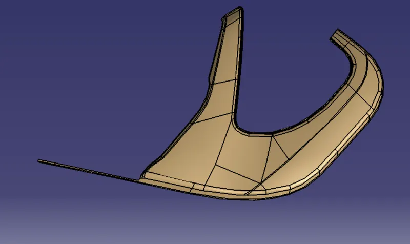
FINAL BODY:-
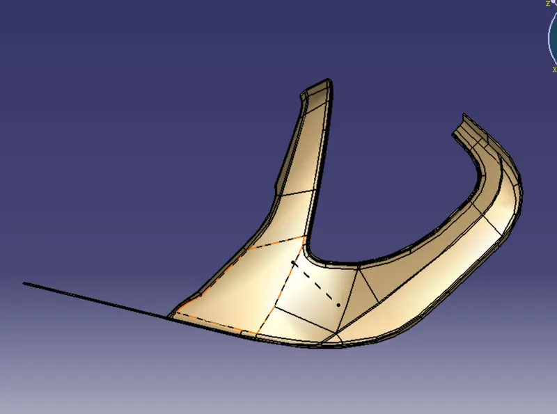
TOOLING AXIS:-
-Frst of all a check the quality of class A surface.
-Look at all the direction through which the tool can move easily .
-I just extracted the class A flat surface created a point and a line simply.
B-SIDE FEATURES:-
HEAT STAKES:-
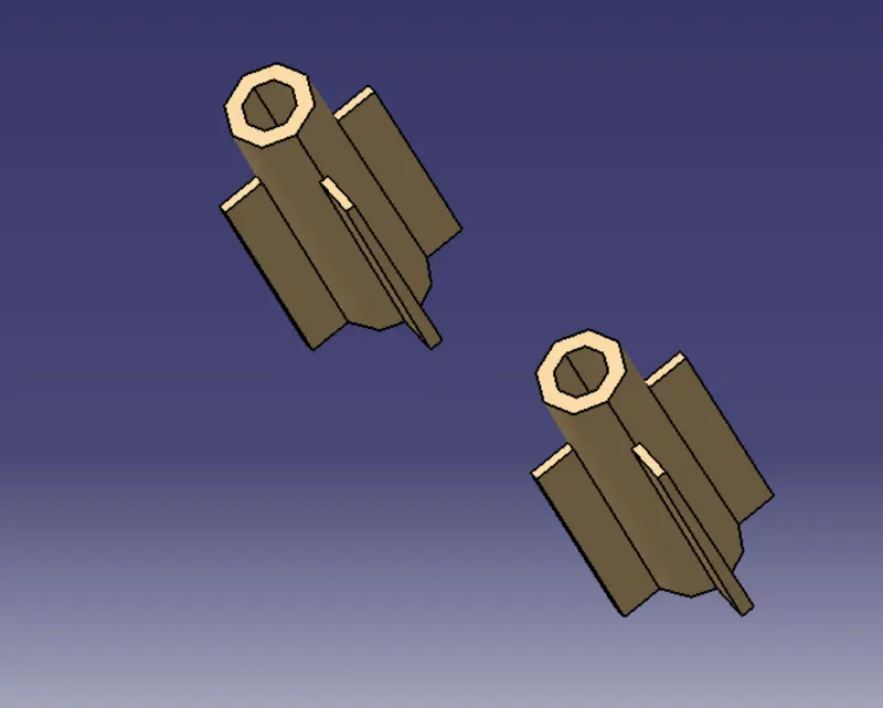
LOCATORS:-
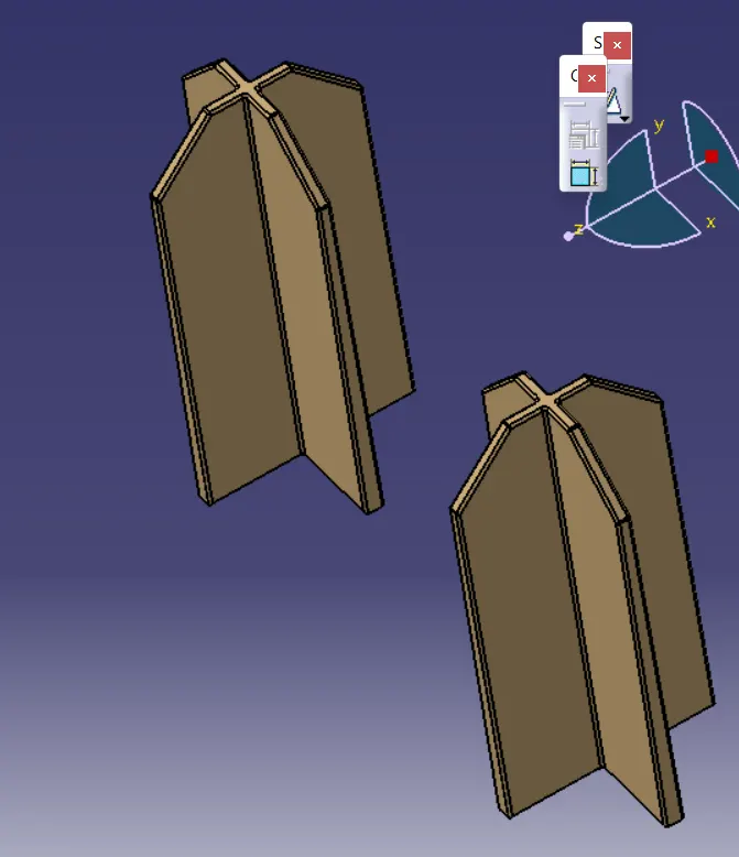
DOG HOUSE:-
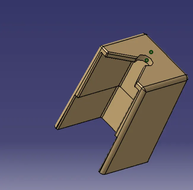
DRAFT ANALYSIS:-
We do perform the draft analysis check for class A surface before we make solid and creation of B-side features. Initially I align the compass to the tooling axis and I gave a 3deg draft angle for the green colour in the colour bar. If the surface is highlighted in green colour the draft angle is given properly for class A surface. If the class A surface is not highlighted fully in green colour, that might be the reason for the draft angle of the class A surface.
SOLID PART DRAFT ANALYSIS:-
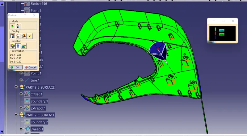
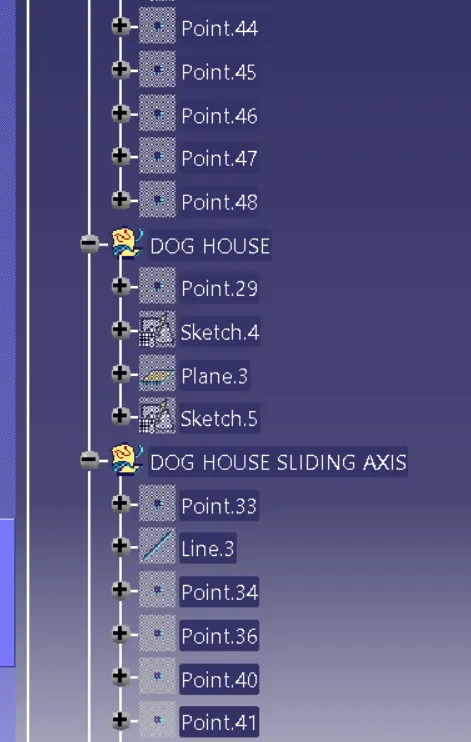
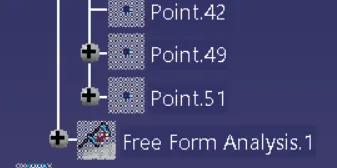
FEATURE TREE:-
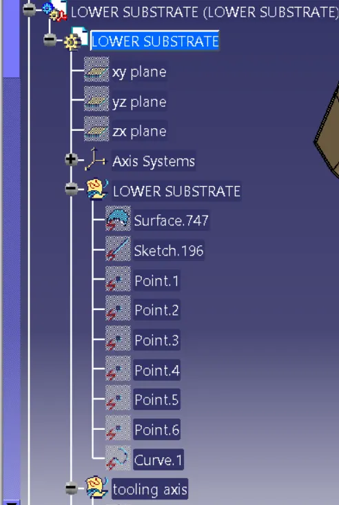
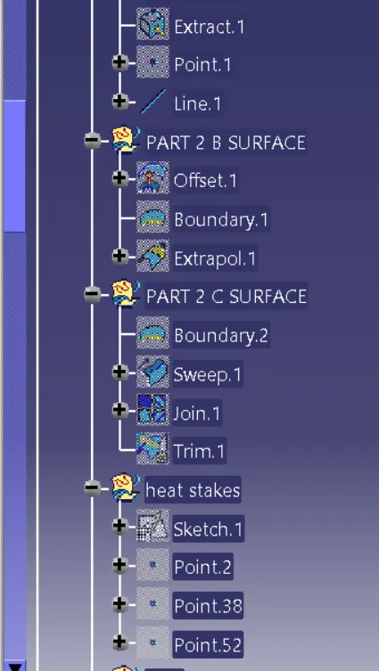
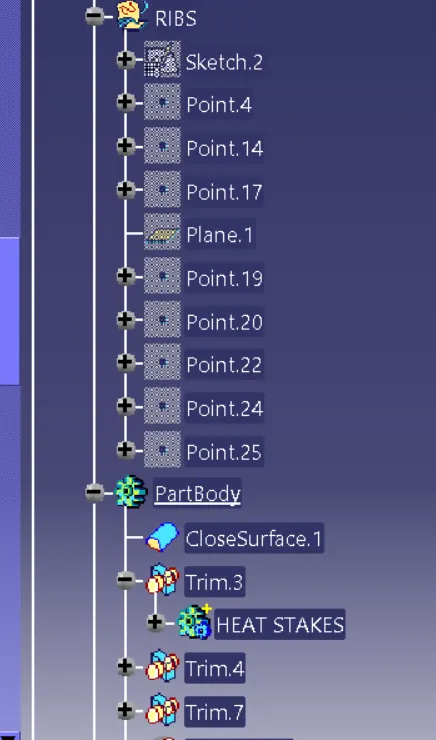
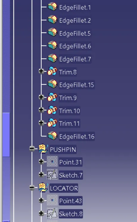
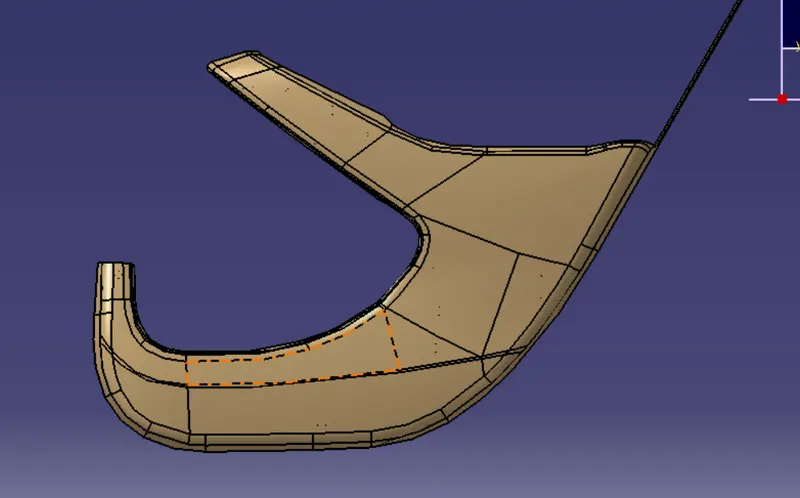
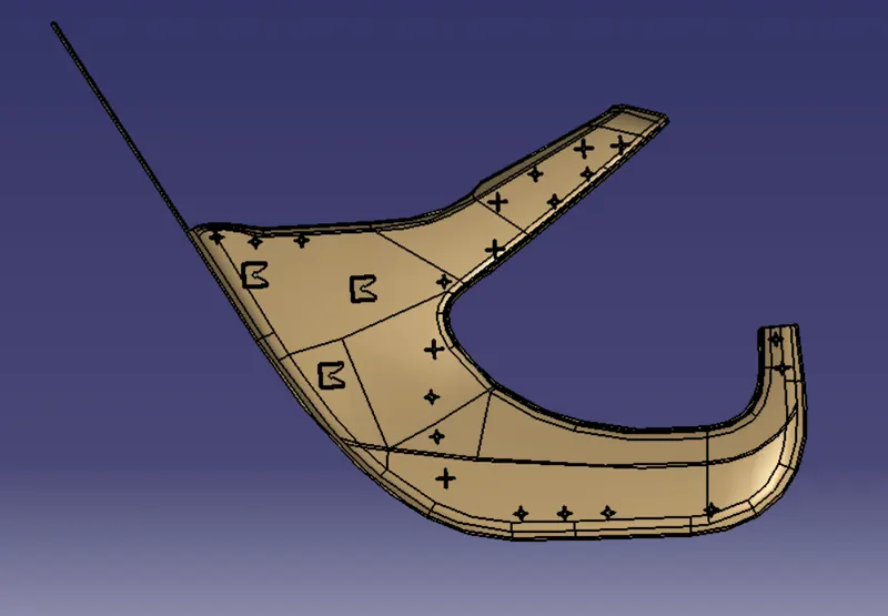
DIFFERENT VIEWS:-
MAP POCKET:-
CLASS A SURFACE:-It is a surface that is provided by the styling team.
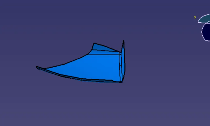
CLASS B SURFACE:-It is a surface that is created by offsetting the class A surface to 3 mm and doing required required modification i.e. the irregularities comes after offsetting the class A surface.
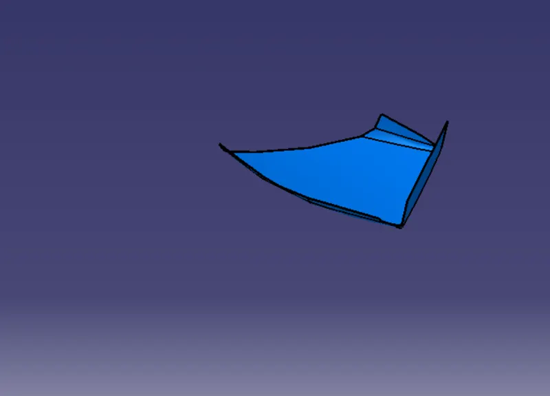
CLASS-C SURFACE:-
- For the creation of class B surface first the boundary of the class A surface is extracted using multiple extract feature
- After the sweep option is used to create the sweep along the tooling axis direction.
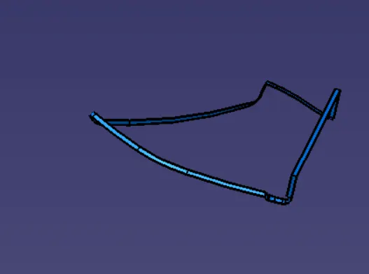
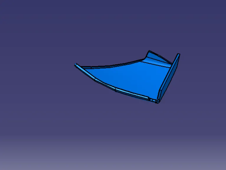
FINAL TRIM BODY-
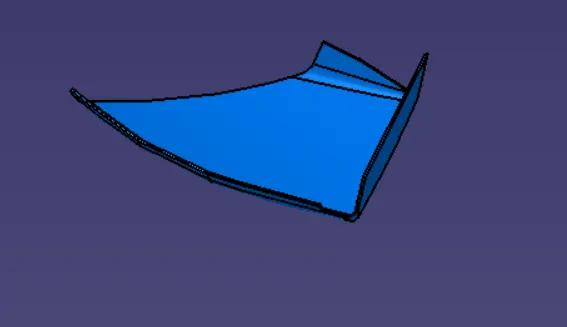
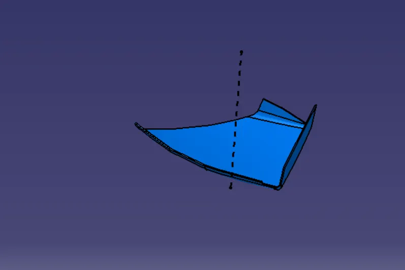
TOOLING AXIS:-
-Frst of all a check the quality of class A surface.
-Look at all the direction through which the tool can move easily .
-I just extracted the class A flat surface created a point and a line simply.
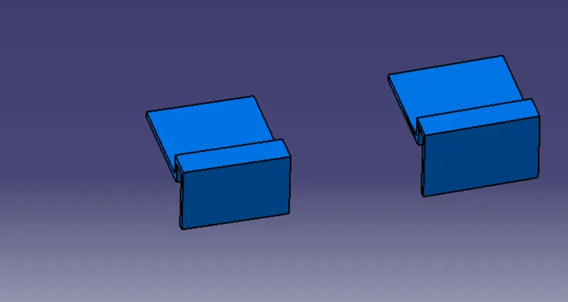
B SIDE FEATURES:-
FLANGE:-
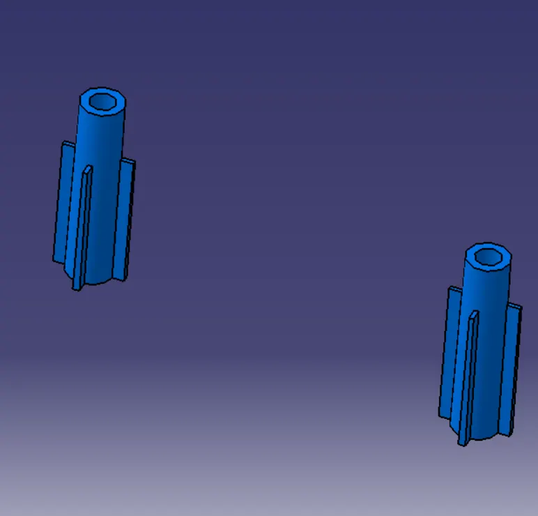
HEAT STAKES:-
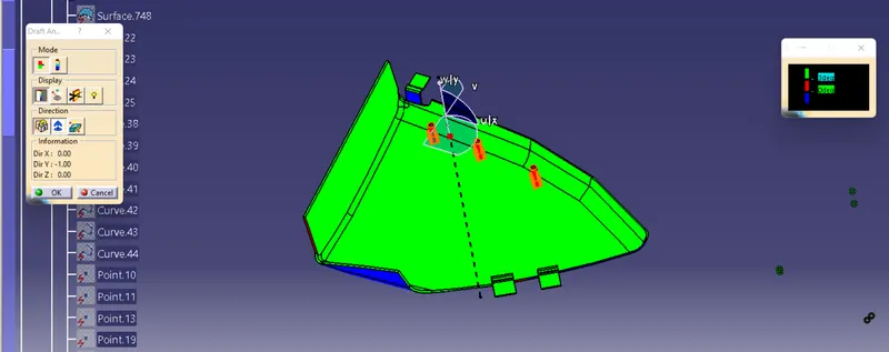
DRAFT ANALYSIS:-
We do perform the draft analysis check for class A surface before we make solid and creation of B-side features. Initially I align the compass to the tooling axis and I gave a 3deg draft angle for the green colour in the colour bar. If the surface is highlighted in green colour the draft angle is given properly for class A surface. If the class A surface is not highlighted fully in green colour, that might be the reason for the draft angle of the class A surface.
SOLID BODY DRAFT ANALYSIS:-
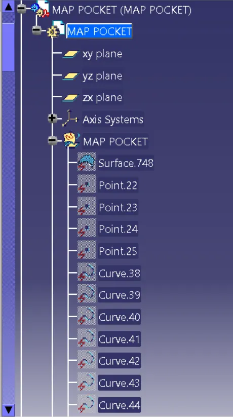
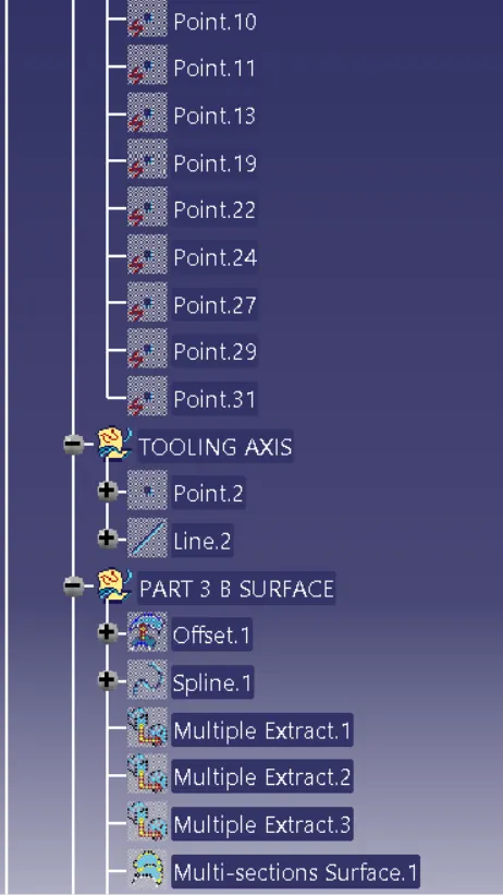
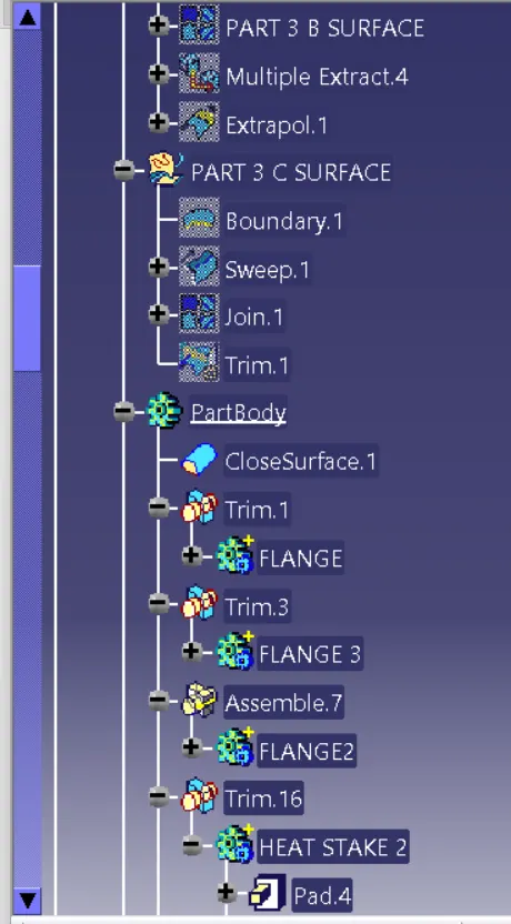
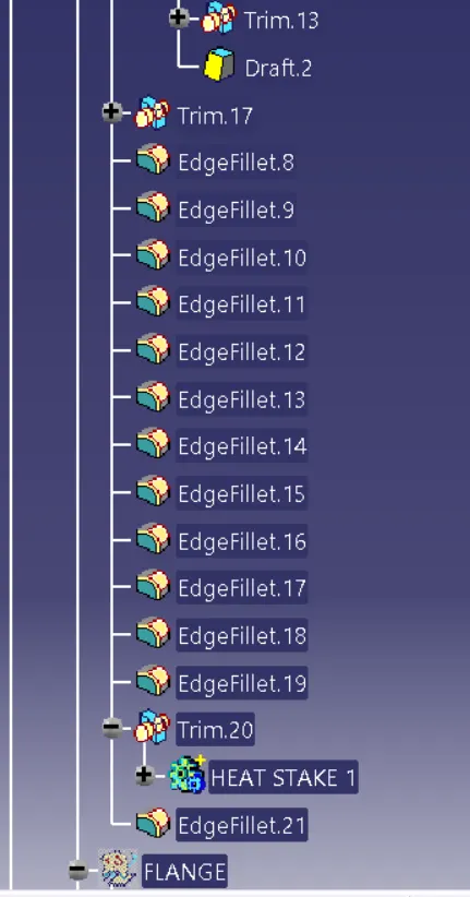
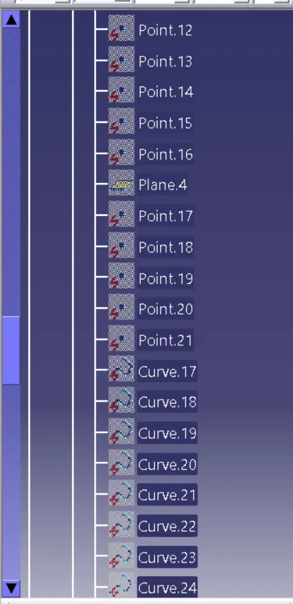
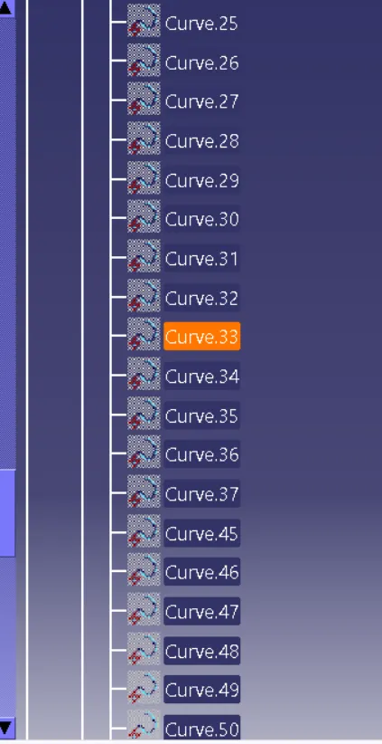
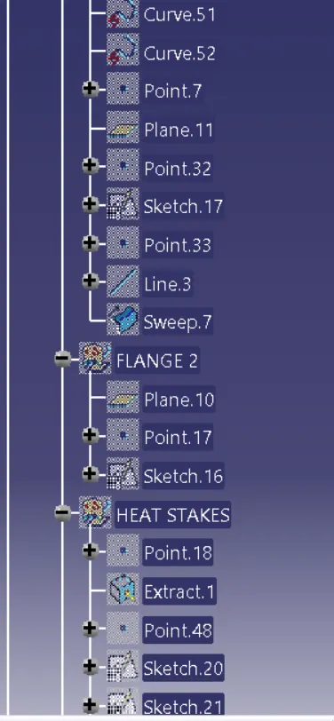
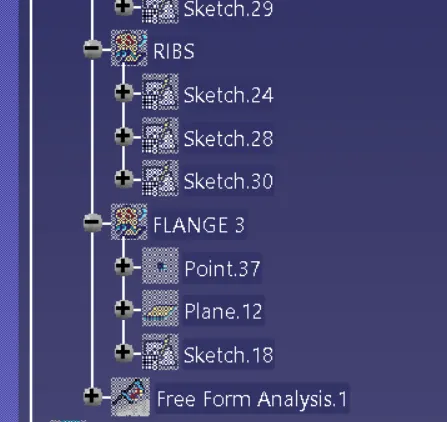
FEATURE TREE:-
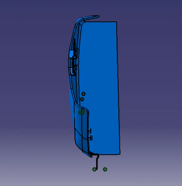
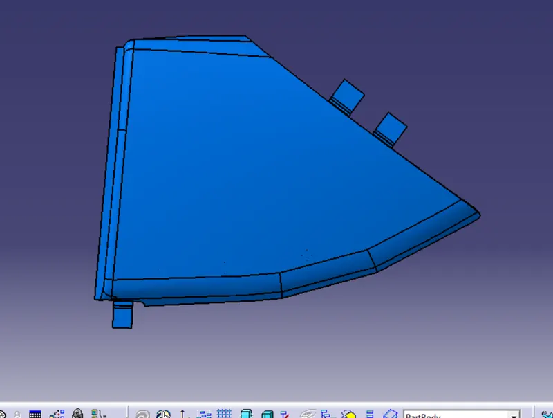
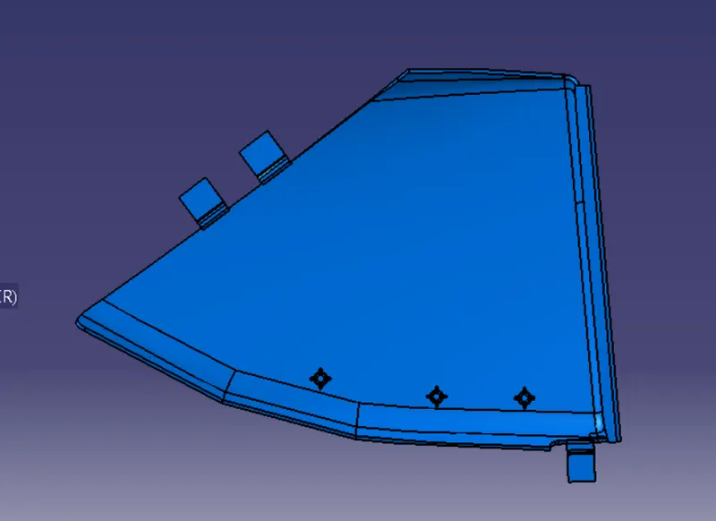
DIFFERENT VIEWS:-
BOTTLE HOLDER:-
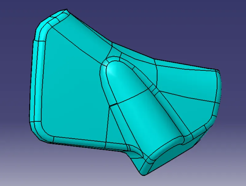
CLASS A SURFACE:-It is a surface that is provided by the styling team.
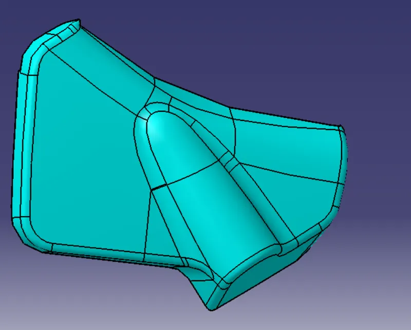
CLASS B SURFACE:-
It is a surface that is created by offsetting the class A surface to 3 mm and doing required required modification i.e. the irregularities comes after offsetting the class A surface.
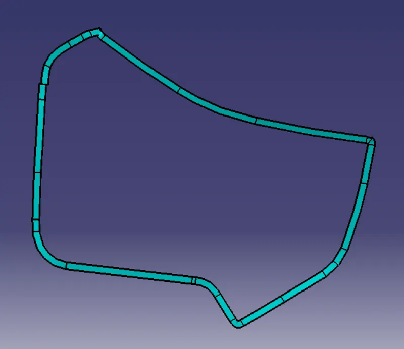
CLASS C SURFACE:-
- For the creation of class B surface first the boundary of the class A surface is extracted using multiple extract feature
- After the sweep option is used to create the sweep along the tooling axis direction.
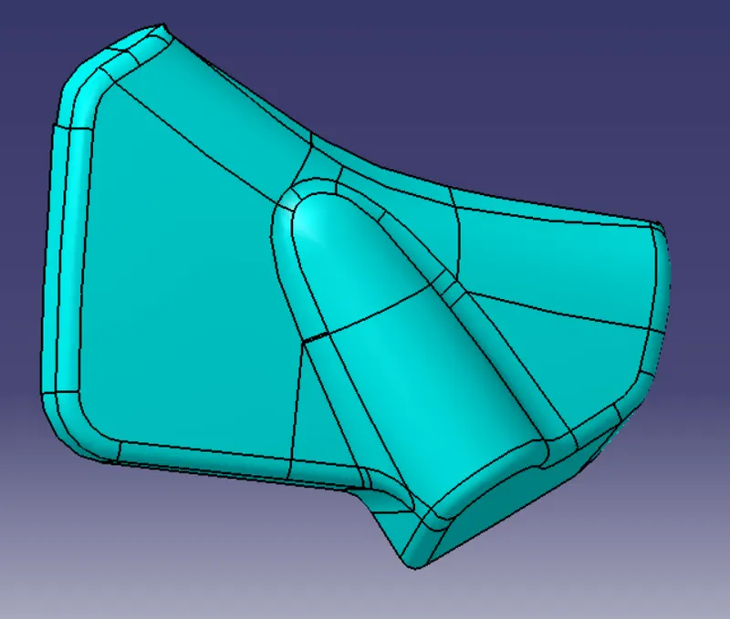
FINAL TRIM BODY:-
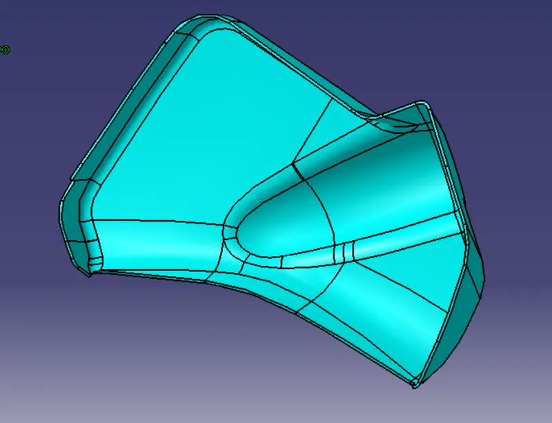
TOOLING AXIS:-
-Frst of all a check the quality of class A surface.
-Look at all the direction through which the tool can move easily .
-I just extracted the class A flat surface created a point and a line simply.
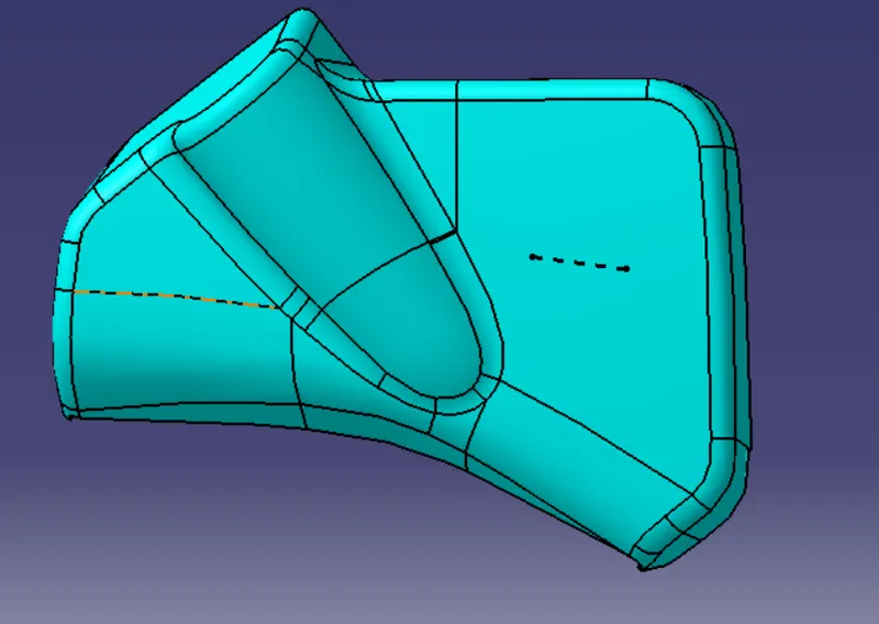
B-SIDE FEATURE:-
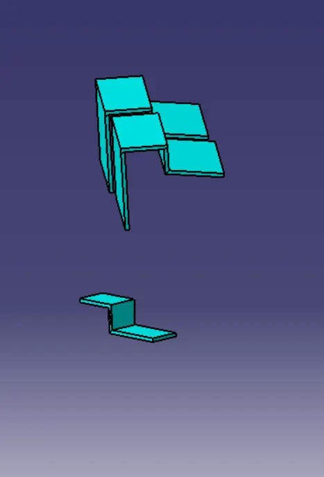
FLANGE:-
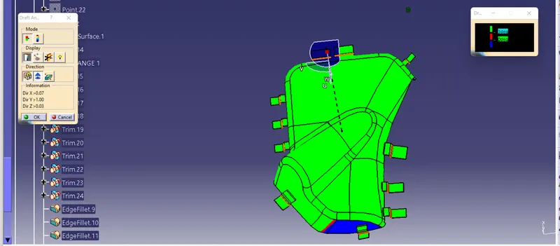
DRAFT ANALYSIS:-
We do perform the draft analysis check for class A surface before we make solid and creation of B-side features. Initially I align the compass to the tooling axis and I gave a 3deg draft angle for the green colour in the colour bar. If the surface is highlighted in green colour the draft angle is given properly for class A surface. If the class A surface is not highlighted fully in green colour, that might be the reason for the draft angle of the class A surface.
SOLID PART DRAFT ANALYSIS:-
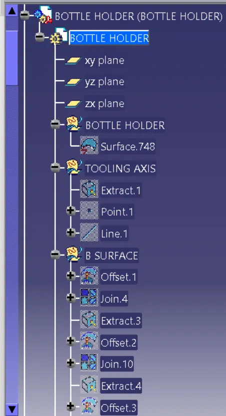
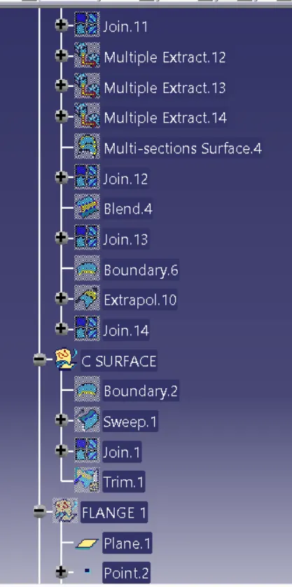
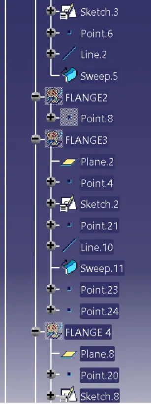
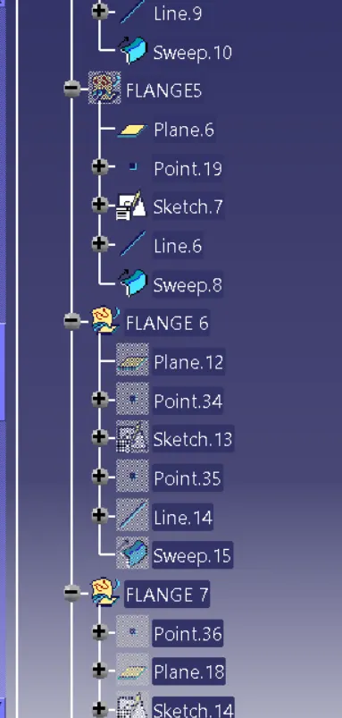
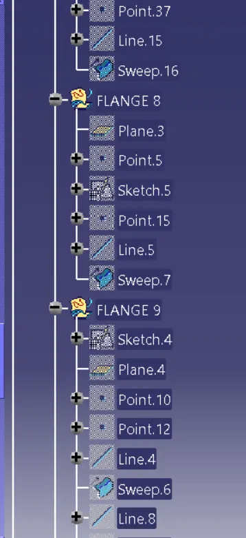
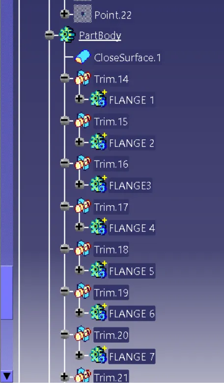
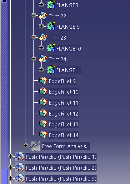
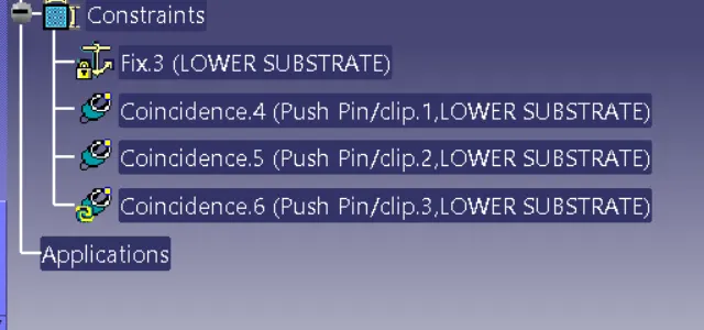
FEATURE TREE:-
FINAL ASSEMBLY BODY:-