Week 11 - Final project
CAR DOOR PLASTIC TRIMS DESIGNED FOR INJUCTION MOLDING
OBJECTIVE
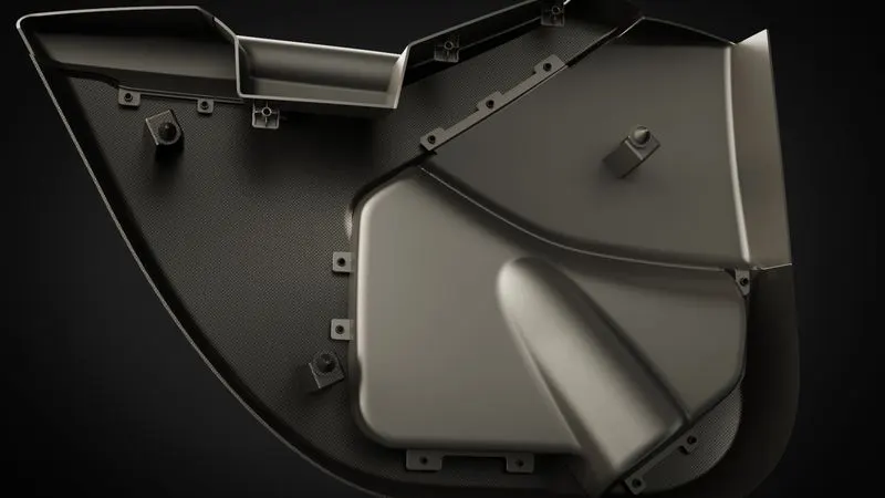
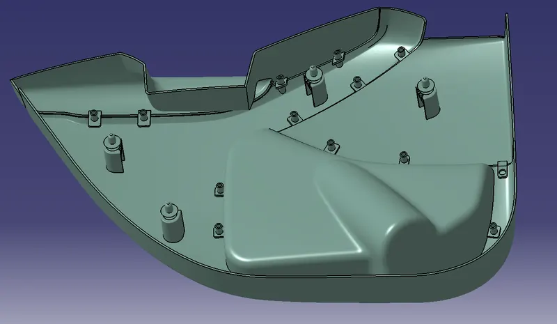
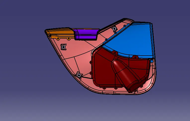
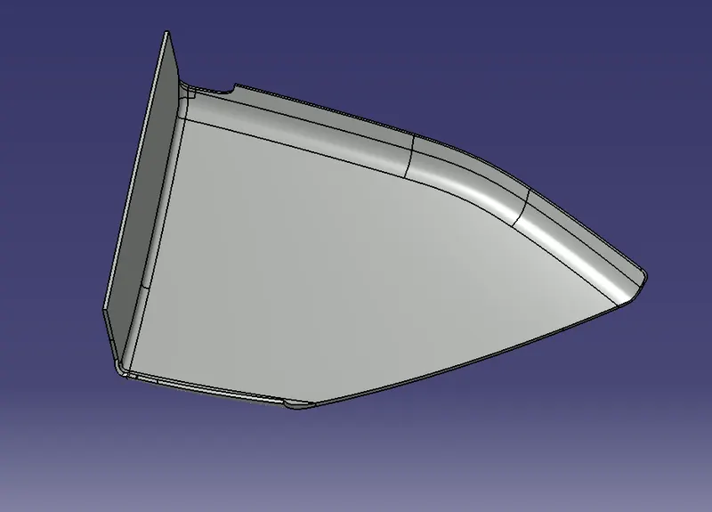
Here i received class A surface of a car door's plastic trims. My objective is to develop the class A surface received into manufacturable product design following the OEM design standards using CATIA V5 surface workbench
CLASS A SURFACE
ABSTRACT
The project report deals with the steps and procedures followed while developing plastic trims for cars door from a class A surface provided, using CATIA V5 surface workbench. It explains the method i followed for creating for the main tooling axis , side core axis, class B surface, class C surface, and final closed body creations, it also explaine the draft analysis performed to check the manufacturability of the products using injuction moulding, various plastic door trims such as map pockets, arm rest, lower substrate etc were successfully developed in this project
PROCEDURE
1 CLASS A SURFACE
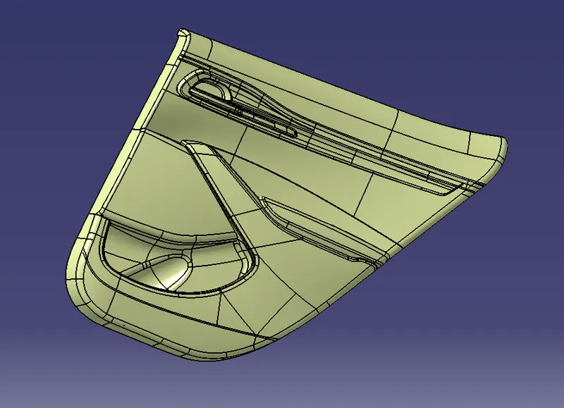
In Automotive industry there will be a dedicated team who will perform the aesthetic designig of various components including the whole vehicle. they will create various concept sketches after ideation. after that, they will also create class A surface of the product , this Class A surface is then passed over to the NPD CAD team, They will initially inspect the Class A surface in order to check if the design is manufacturable or if it is following the engineering principles, if there are any issues about the design, they will contact the product design team and will ask to modify the Class A surface in order to solve the problem, Here i received the Class A surface shown above.
PLASTIC PARTS
1 , Map pocket upper part
2, Map pocket lower part
3, Arm rest split parts
4, Lower substrate
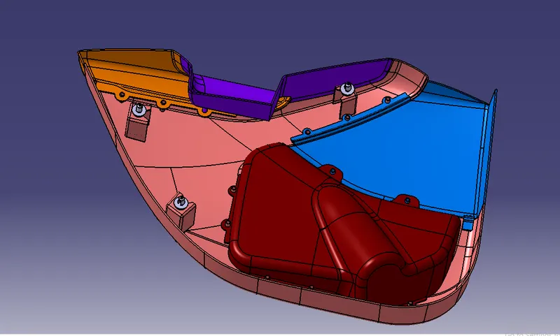
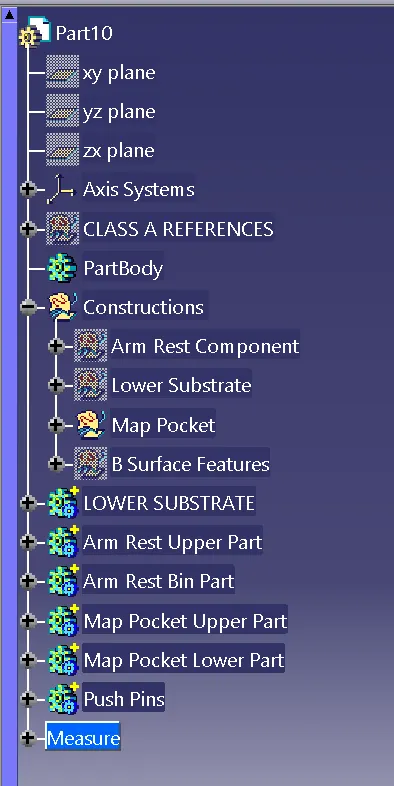
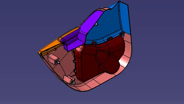
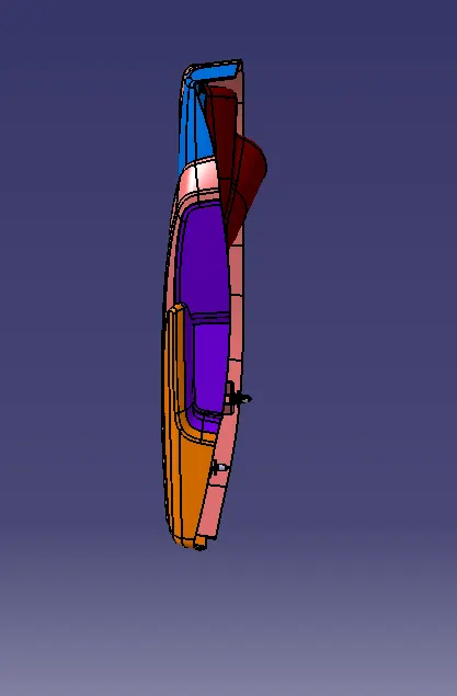
1 Map pocket - upeer part
Initially, I exctracted the Class A surface reqired for each part from the main input, Then started working on them one by one, Here i extracted the Class A surface of map pocket from input as shown in below
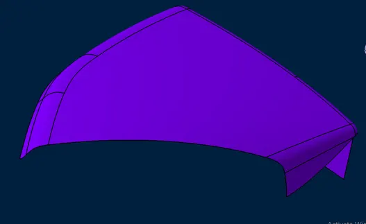
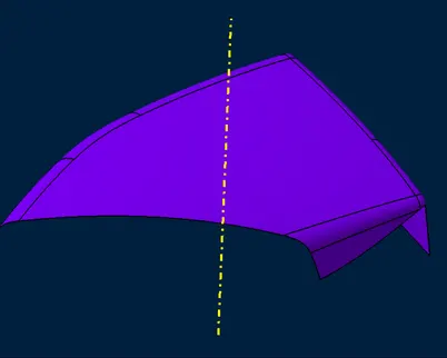
Next , main tooling axis was created by applying a Zero distance value on the surface as shown below
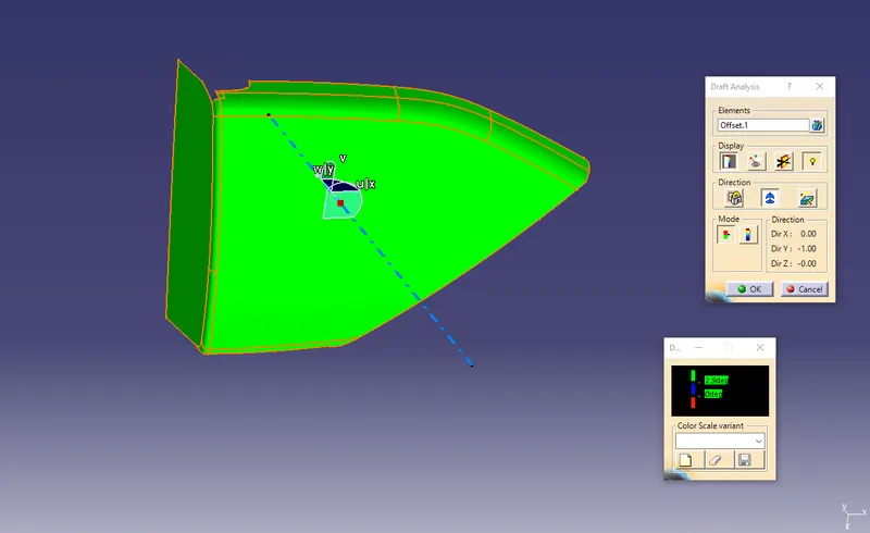
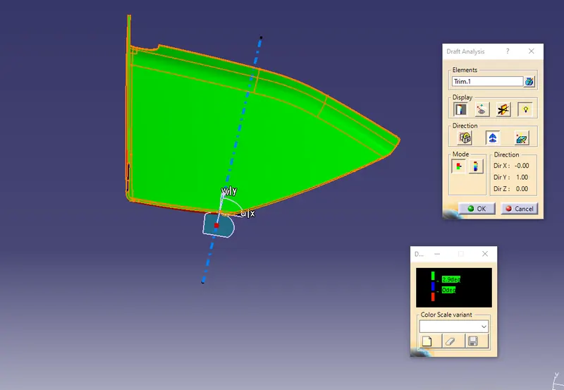
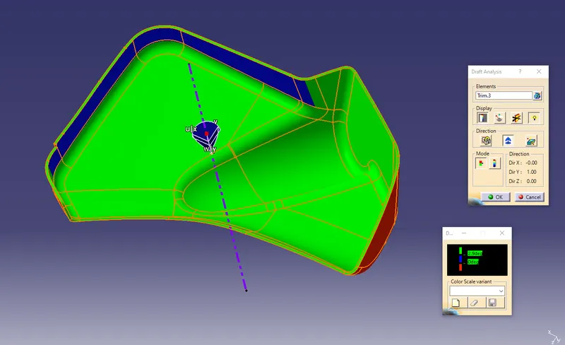
Next the surface was inspected using draft analysis as shown below . In Industry if there is any issue with the surface after inspection, Engineers mus discuss the issue with the aesthetic design team whom provide the Class A for troubleshooting the issue,
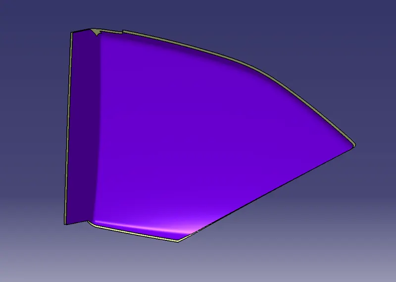
Class B surface development
Class B surface created from the Class A surface using 'EXTRACT/MULTIPLE EXTRACT' and offset option, major surfaces of Class A surface was offset at a distance of 2.5 mm thickness, fillet were applied after necessary calculation
Class C surface development
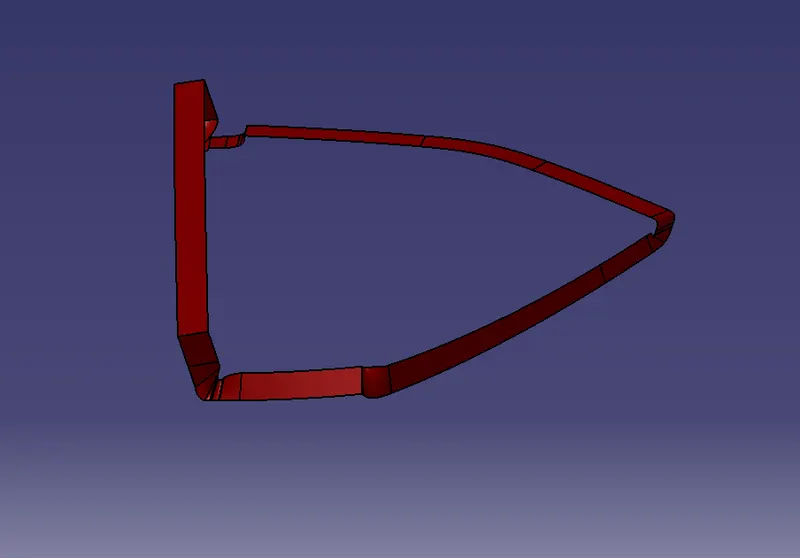
Class C surface was swept along the boundary of a Class A using 'SWEEP' option at an angle of 3 degree outwards with respect to tooling direction. in some areas 90 degree sweep was applied ,Finally all the swept surfaces were trimmed and joined together.
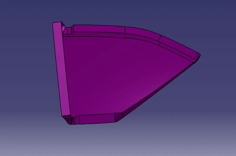
Then Class A surface of map pocket and Class C surface were joined together as shown in below
After joining class A and class B surfaces , it will trimmed together with the class B surface in order to form the closed surface as shown below
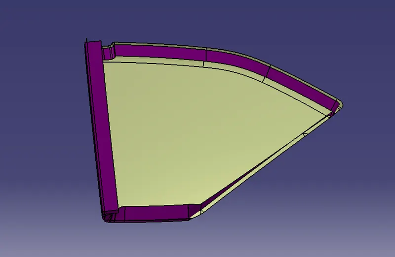
A part body was formed using the closed surface
2 MAP POCKET LOWER PART
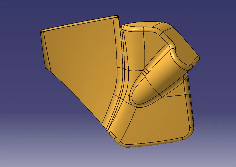
Lower part of the map pocket was also created by following the same steps and procedure , initially Class A surface was extracted from the input surface as show in below
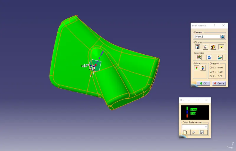
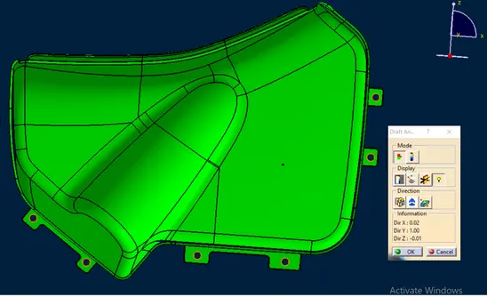
Then i performed the draft analysis thw walls were below 3 degree (blue), If it is an industrial project we must discuss with thw aesthetic design team in oerder to avoid this blue in edges of walls , but it is acceptable in this project ,
Then as earlier the Class B surface was formed using Class A surface , the offset distance was 2.5 mm as it is the thickness of the component
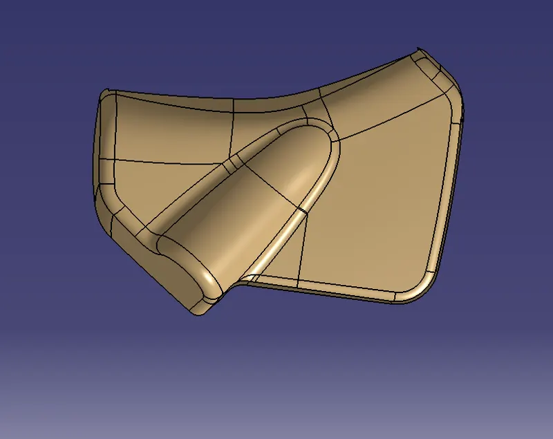
Class C surface was swept along the boundary of a Class A using 'SWEEP' option at an angle of 3 degree outwards with respect to tooling direction. in some areas 90 degree sweep was applied ,Finally all the swept surfaces were trimmed and joined together.
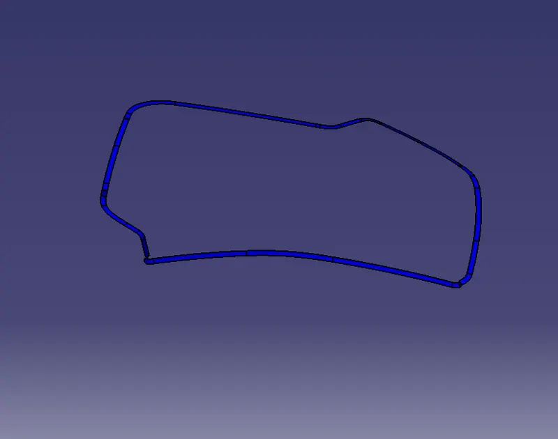
Then Class A surface of map pocket and Class C surface were joined together as shown in below
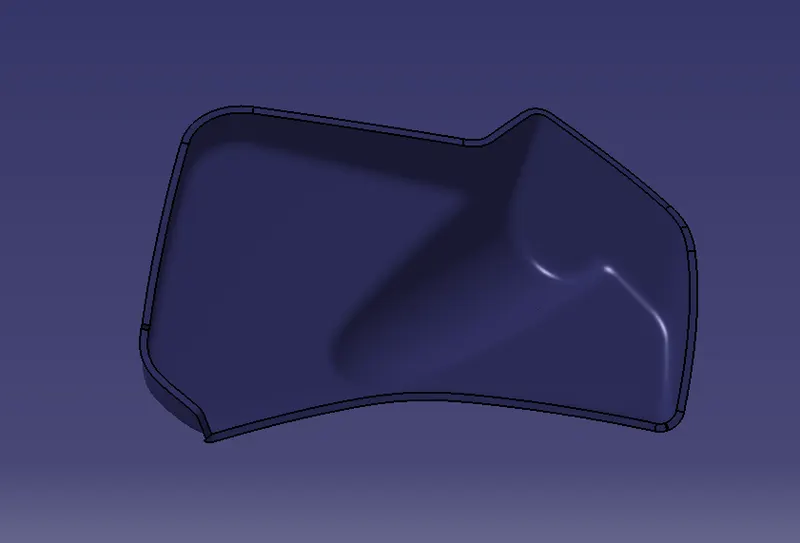
After joining class A and class B surfaces , it will trimmed together with the class B surface in order to form the closed surface as shown below
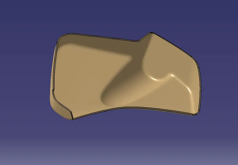
A part body was formed using the final closed surface , draft analysis of the final closed body was successfully performed,
3 LOWER SUBSTRATE
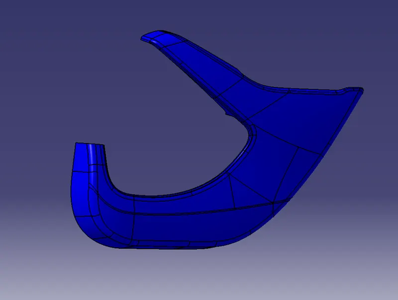
It is on the lower substrate all the earlier designed components going to fix at first, I extracted surface for class A surface from the input surface
Made a tooling axis for inspecting the class A and also for sweeping the class c surface
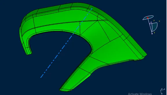
There was no issues detected on the class A surface . so i proceeded to further steps for designing the produst, The surface was almost flat in shape, I offset it for 2.5 mm for creating the class B as shown in the next page
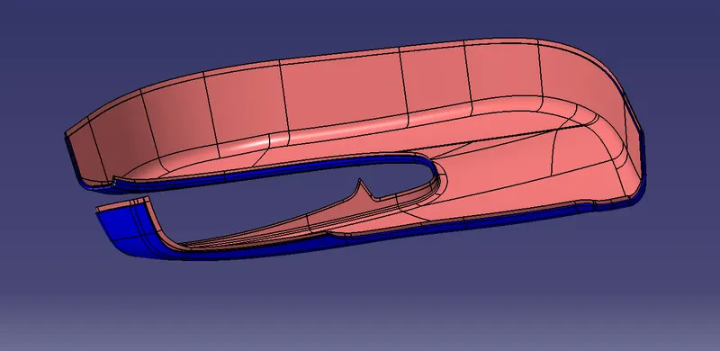
Class C surafce was created by using sweep option, trimmed and joined all the surface of class C as shown below,
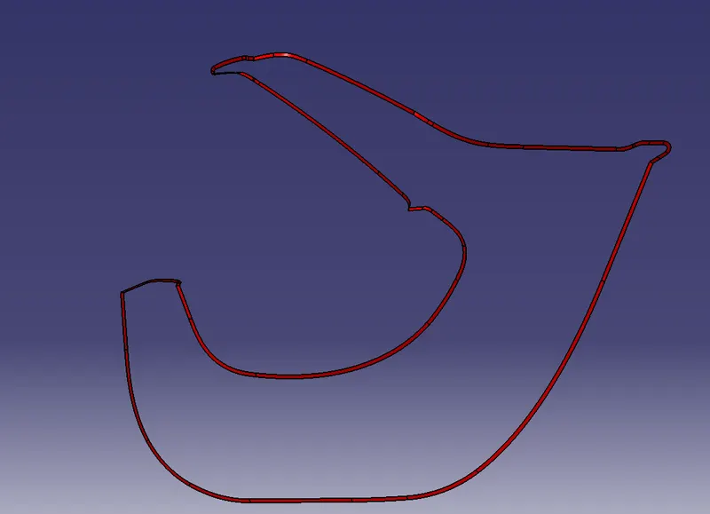
Then I joined both the class A and Class C surface together and trimmed it along with the class B surface for creating the final closed surface
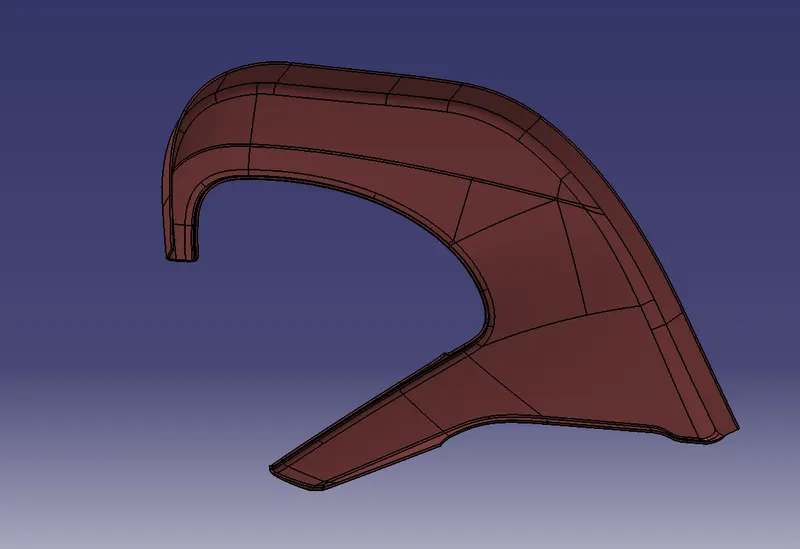
Then a part body was created using the closed surface and heatstakes with ribs were designed with 0.5 degree draft , on the B surface side for attaching the map pocket and armrest plastic parts , also two doghouses were fixed on the same side for fixing the locating pins dog hose were fixed at a distance 3 times of width of its side wall from features of walls in front of it for clearing the lifter during the injuction moulding,
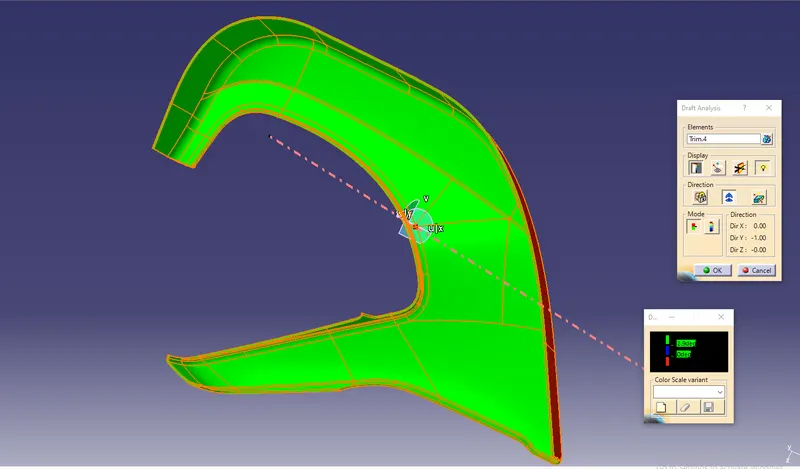
Draft analysis of the product was successfully performed with minimum 3 degree draft angle
ARM REST
Arm rest consist of two split parts, As the tooling was complicated if it manufactured as a single component , i split it into two
ARM REST PART-1
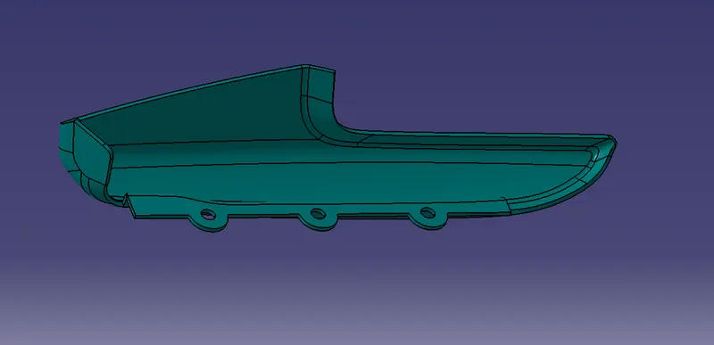
I extracted the required surface for class A of part 1 from the input surface
class B surface was created from the Class A surface using 'EXTRACT/MULTIPLE EXTRACT' option, class B surface was offset at a distance of 2.5 mm thickness from the class A surface, fillet were applied after necessary calculations,
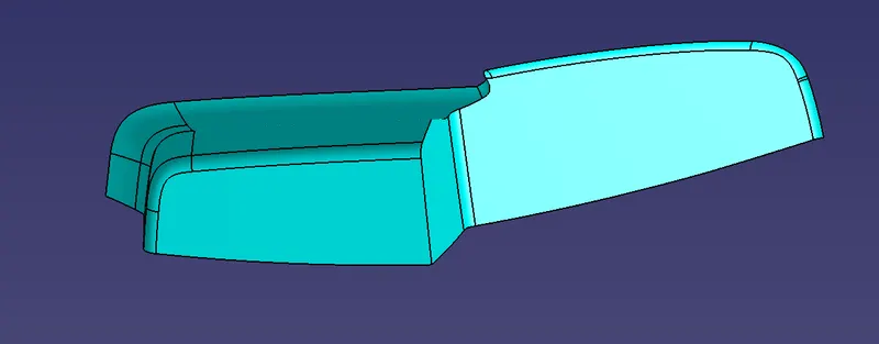
Class C surface was swept along the boundary of a Class A using sweep option at angle of 3 degree outwards with the respect to main tooling direction , Finally all the swept surfaces trimmed and joined together.
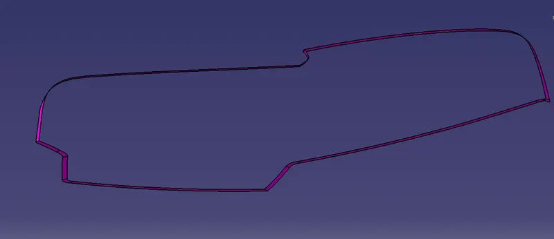
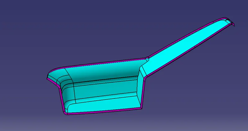
At last, Class A and Class C surfaces were joined together and trimeed it along with the class B surafce , Thus a closed surface was formed as shown in below
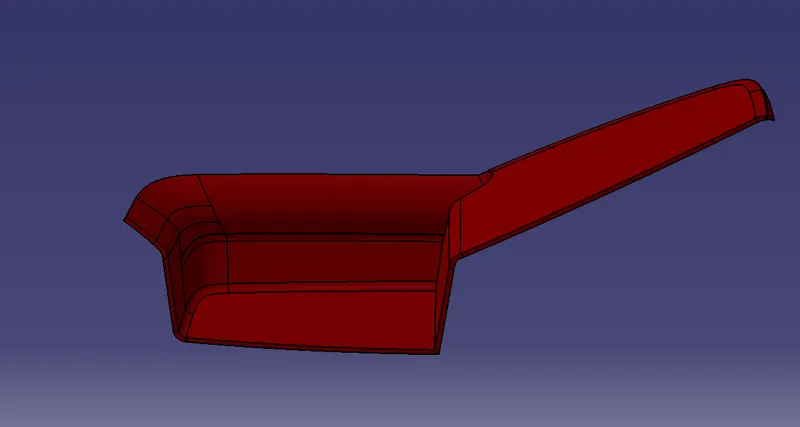
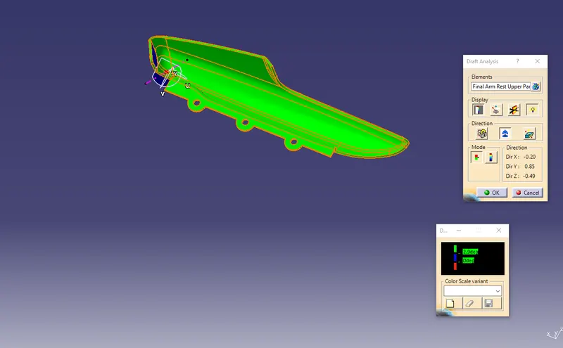
Applied a main tooling axis and side core axis on the surface for draft analysis,
Successfully inspected the class A surface and closed body ,
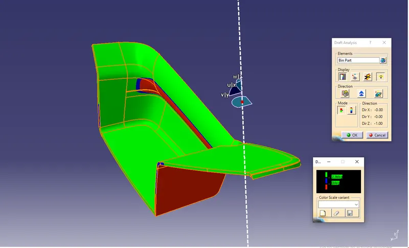
ARM REST PART-2
The second part was also designed as part 1, following the same procedures with tooling axis
Class A surface extracted from the input surface,
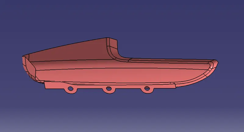
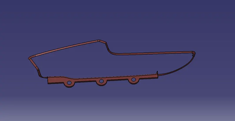
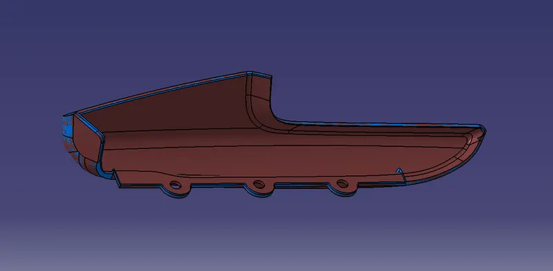
Class C surface was swept along the boundary of a Class A using sweep option at angle of 3 degree outwards with the respect to main tooling direction , Finally all the swept surfaces trimmed and joined together.
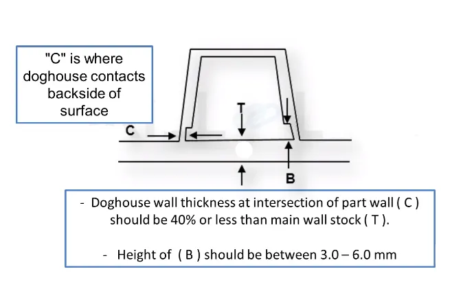
Design guidelines
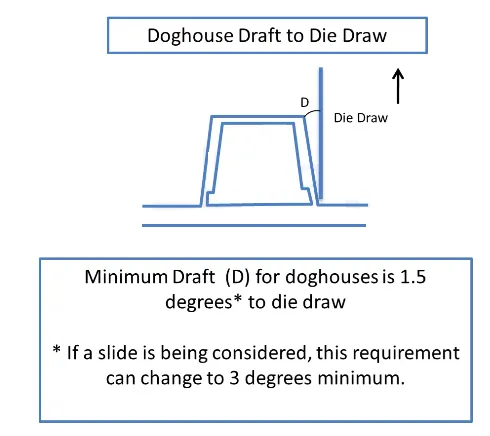
Also the minimum distance between the walls at top portion should be 12 mm
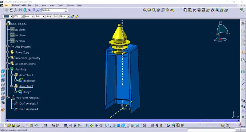
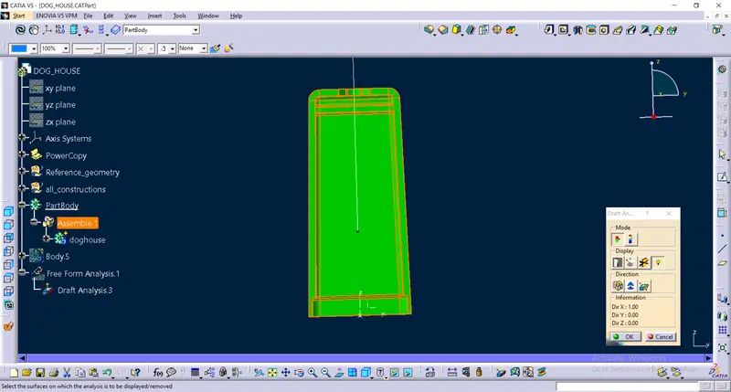
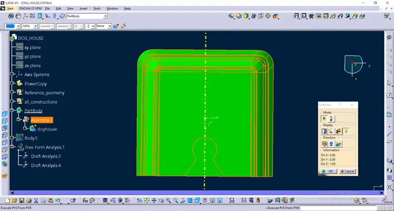
Thus following all the above guidlines I created the doghouse for locator pin as shown below
Design guidelines for screw boss
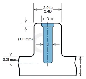
Avoid bosses that merge into sidewalls because they can from thick section that lead to sink instead , the bosses away from the sidewall, and if needed , use connecting ribs for support
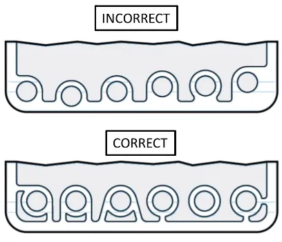
Consider using open boss design for bosses near a standing wall, Avoid bosses that marge into the sidewalls because they can from thick section, that lead to sink, instead, position the bosses away from the sidewall, and if needed , use connecting ribs for support , consider using open boss designs for bosses near a standing wall.
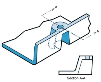
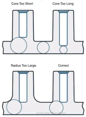
Normally the boss hole should extend to the base-wall level, even if the full depth is not instead for assembly. shollower holes can leave thick sections , resulting in sink or voids, deeper holes reduce the base wall thickness , leading to filling problems, knit lines, or surface blemishes the goal is to maintain a uniform thickness attachment will because of the required draft, tall bosses - those greater than five times thier outside diameter -can create a filling problem at their top or thick section at their base .
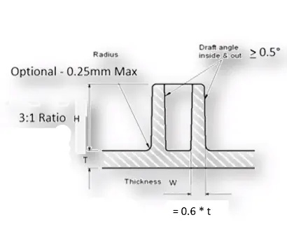
General Guidelines for screw bosses
- Draft - 0.5 degrees on wall of boss
- Thickness typically 60% of nominal wall at base
- Height to diameter ratio -3:1
- Radii-0.25 mm maximum radii
- Boss guessets must meet rib guideline
- Need to plane ahead for type of ejection
- If lessthen 25mm tall , draft is not required when sleeve ejection is used
- Over 25v mm tall, draft is required on out side wall only sleeve ejection is used
- If sleeve ejection not used, draft is required on all walls
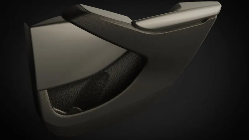
Final image renderings of the model