Week 11 - Final project
DOOR TRIM PANEL
AIM; To design a door trim panel of an automotive using catia v5.
OBJECTIVE
The main objective of the project is to create side door trim panel from the given class A surface and give attachment features to it like dog house , heat stakes, 4 way and 2 way locators, flanges , ribs for support. and finally performs draft analysis on it to check wheather it is manufacturable or not .
INTRODUCTION
The door trim panel of a car is the interior parts of the door which contains the most controls and decorative parts, the main components of interior door panel of a car consist of the following parts
- Arm rest
- Map pocket
- Upper substrate
- Door lower substrate
The stages in automotive product life cycle are the following
- concept sketch
- styling class A
- Feasibility check
- concept validation
- new product design
- product development
- prototyping
- design validation
- pilot production
- mass production
In this project we are doing the 5 th stage as mentioned above ie, New product design, here we are creating a new product from the given class A surface. The steps for the creation of the new plastic components from the class A surface are given below
- Creation of tooling axis
- Creation of class B surface
- Creation of class C surface
- Creation of closs body
- Draft analysis
TOOLING AXIS CREATION
Tooling axis creation is the first step , here in this project the tooling axis is created using bisecting method and normal to surface method. The tooling axis or tooling directiuon is the direction in which the mold opens.By using this tooling axis as referance we are giving draft for each part, and we draft analysis are also performing using the tooling axis as reference, here we want to create tooling axis for every part seperately.
DRAFT ANALYSIS
Draftf analysis is done to check whether that the designed part is manufacturable or not based on its draft condition as per industrial standards . As per the industrial standards the nominal draft for plastic components are given as 3 deg , in some certain cases draft of max 7.5 deg to .5 deg also given , like in ribs and screwboses draft of 0.5 deg are given as draft.Draft angles are given to the part to ensure the proper ejection of the component from the dies or molds. The cavity and core are opened in the direction of tooling axis. Draft analysis are done at two stages mainly in a part design process, first analysis is done on class A surface before the design starts and next is after the creation of final body by giving thickness to close body.The procedure for the draft analysis are the following
- Once the tooling direction is created we can do draft analysis .
- At first change the view mode to customized view and select material mode. After that open the draft analysis tool.
- Click on the compass and place the compass along with the tooling axis and then click on the surface to be analysed ,then the catia shows the draft analysis of the surface ,we can select the required draft angle as per our need here select the draft of 3 deg as per industrial standards for the main part body and select currosponding value for the draft analysis of the attachment features
- we can identify the draft of the surface by various colour ranges.
PROCEDURE OF DESIGN
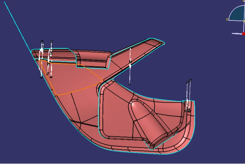
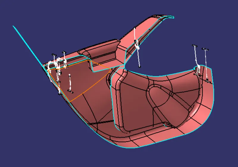
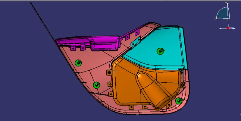
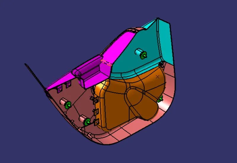
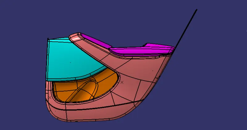
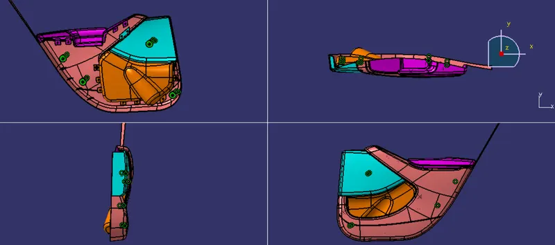
The above fig, is the image of the given class A surface totally there are 4 individual parts in the class A given, the design of each part is done seperately , the parts that are given are the following
- Door arm rest
- Door lower substrate
- Map pocket
- Bottle holder
DOOR ARM REST
1) Class A surface
In the case of door arm rest the given surface is not the classA surface we want to offset the given surface for 2mm for getting the class A because the given surface is the surface of the outer cusion of door arm rest.
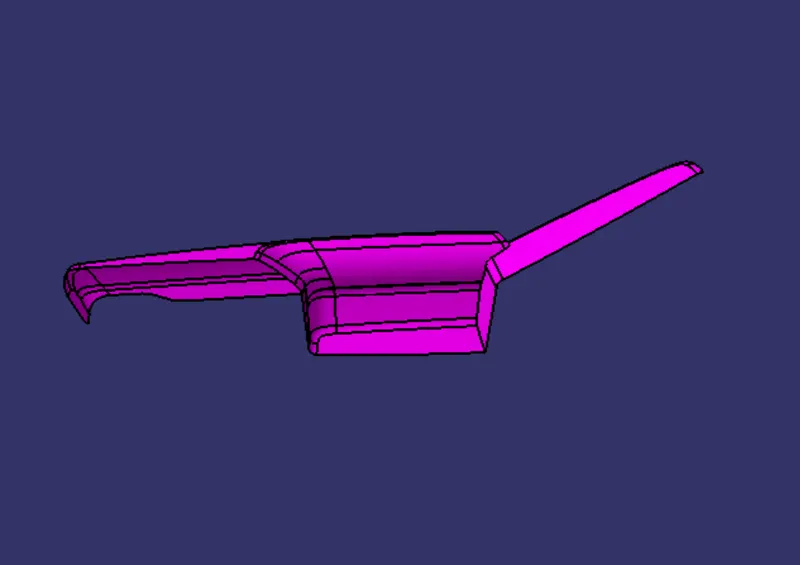
2) Creation of tooling axis -
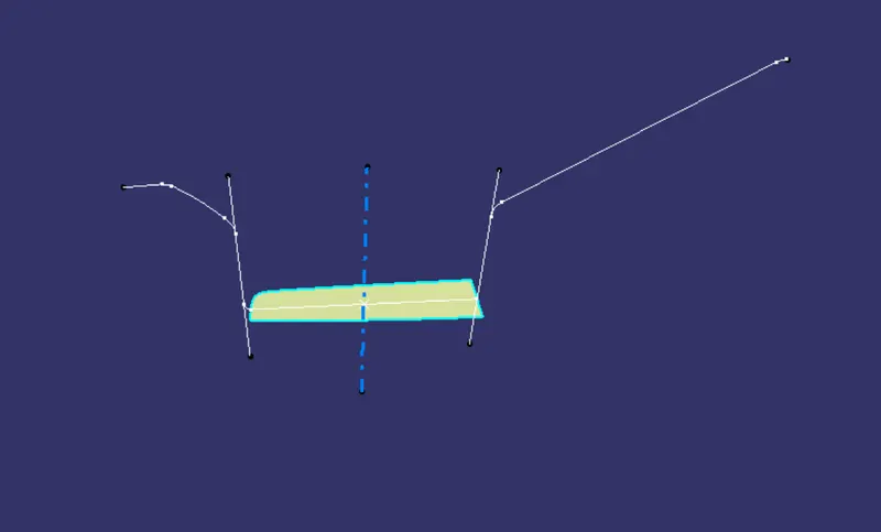
The first step is the creation of tooling axis , for that extract a surface from the class A as shown in fig below and created a point on it centre and inserted an axis system at that point and then by taking intersection of the class A surface by taking the point as reference and zx plane and created lines through the points of the intersection in two sides and by using bisecting comand in the line and created a bisecting line for the above line through the point created and taken that line as the tooling direction.
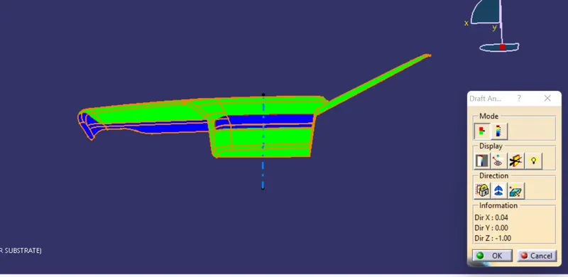
3)Draft analysis
First draft analysis is performed on the class A . some portion of the class A is not clearing the draft as shown in the image below, we dont have the provision to change the class A surface so we move with the surface.
4) class B surface
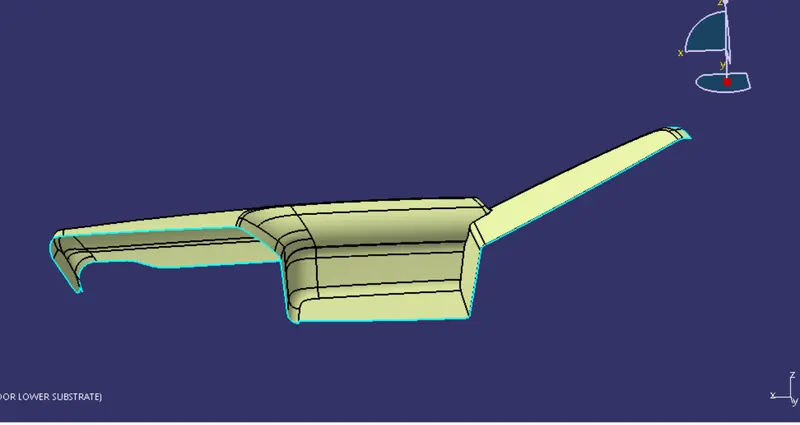
Class B surface is created by direct offseting of the class A surface to 2.5 mm as per the master section given. while offseting class A some patches will come and we want to work on it to get the proper class B surface.
5)Class c surface
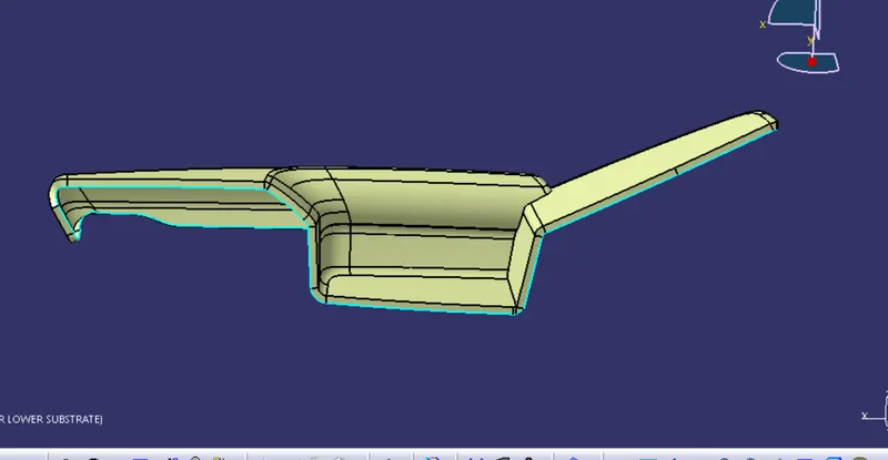
Here in the below image the joined class A with class C surface is shown, the class C surface is created by using sweep option with reference to class A surface by giving reference to the surface comand and with draft direction command.
6)Create closed body
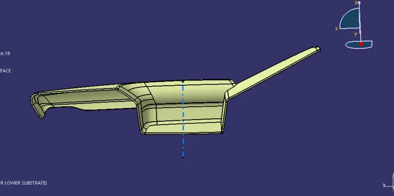
Closed body is created by trimming the class B surface and the joined class A and C surface. after creating the closed body check whether there is any gap or boundary exist using boundary tool.After that create solid body by using close surface method.
7)Draft analysis
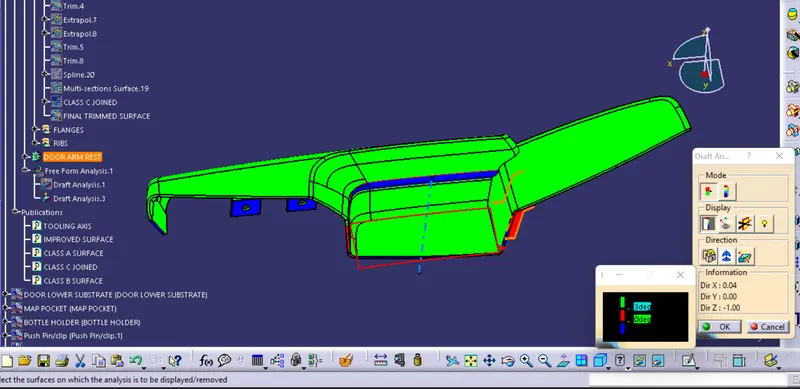
After the creation of solid body perform the draft analysis, here also some portions are not clearing the draft this is because of the class A surface.
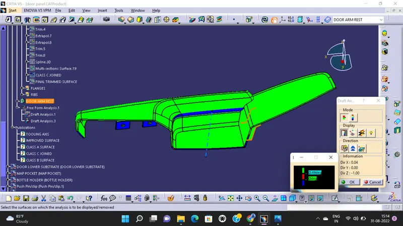
Draft analysis after giving attachment features with draft of .49 deg , actually the draft is .5 but thier may be some chance for the minimal deviation thats why it is takes as .49 deg.
DOOR LOWER SUBSTRATE
1) Class A surface
Here the given surface is the class A surface, publish the class A surface
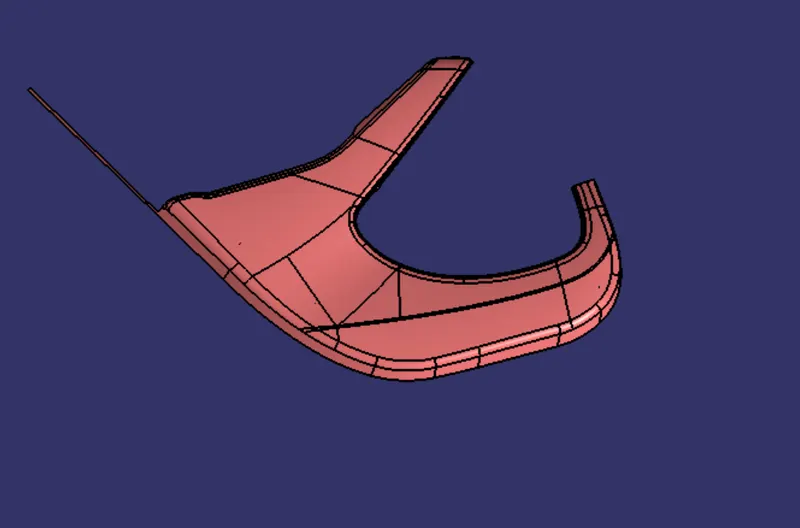
2) Creation of tooling axis
Tooling axis is created by normal to surface method for that first extract a surace and created a poin on it and then using point to direction command create line in y direction as shown below
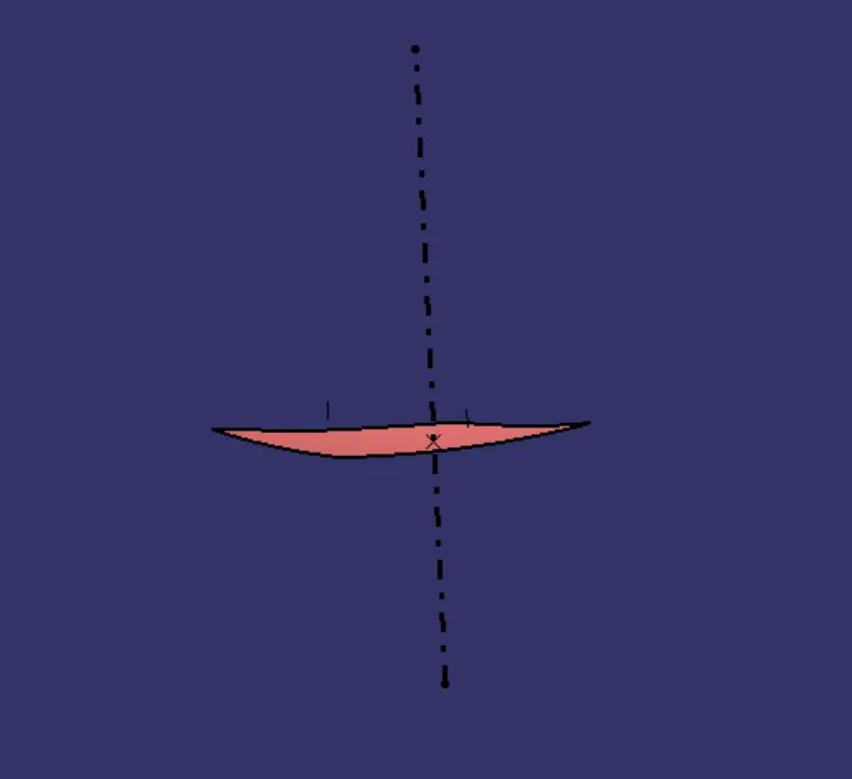
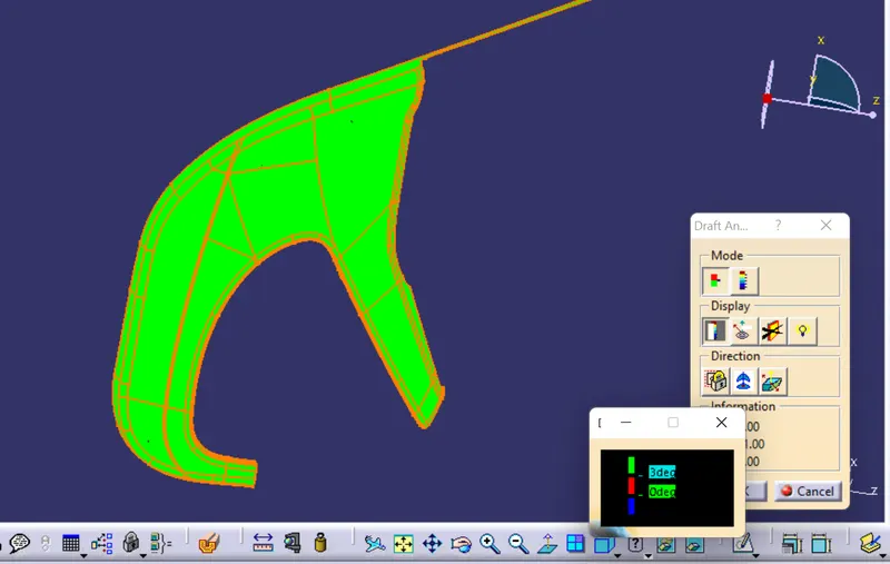
3)Draft analysis
Draft analysis is done on class A surface, here all the surface clearing the nominal draft of 3 deg as shown below.
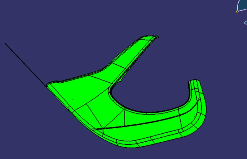
4) class B surface
Class B surface is created by direct offseting of the class A surface to 2.5 mm as per the master section given. while offseting class A some patches will come and we want to work on it to get the proper class B surface.
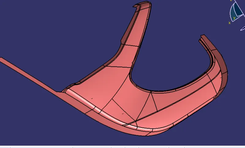
5)Class c surface
Here in the below image the joined class A with class C surface is shown, the class C surface is created by using sweep option with reference to class A surface by giving reference to the surface comand and with draft direction command.
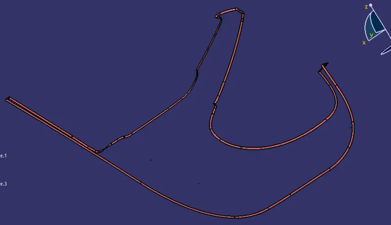
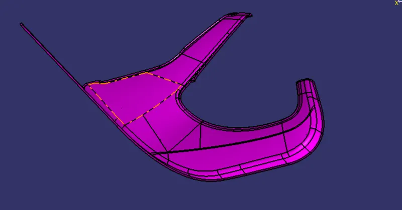
6)Create closed body
Closed body is created by trimming the class B surface and the joined class A and C surface. after creating the closed body check whether there is any gap or boundary exist using boundary tool.After that create solid body by using close surface method.
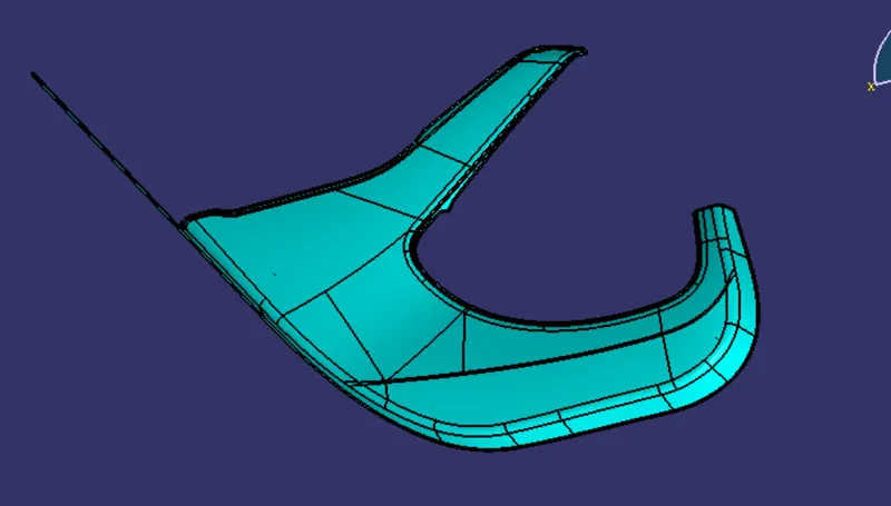
7)Draft analysis
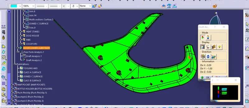
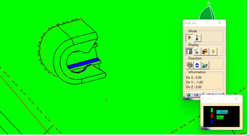
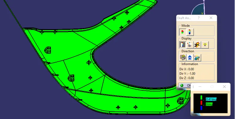
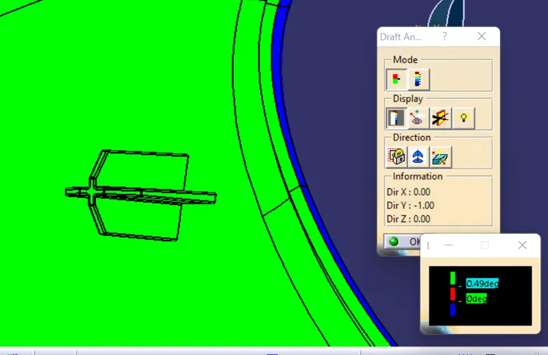
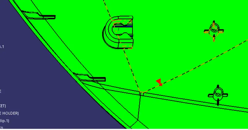
After the creation of solid body perform the draft analysis,here draft analysis is done with two values one for the main part body and one for the attachment features like dog house , heat stakes, ribs, locators etc. Here the main body clearing the min draft of 3 deg in all portions. dog house outer surface is clearing the draft of 1.49 deg the given draft is 1.5 deg, there may be chance of minimum deviations, heat stakes clearing minimum draft of .47 deg given is .5 deg , locators and ribs clearing min draft of .49 deg as shown below.
MAP POCKET
1) Class A surface
Here the given surface is the class A surface, publish the class A surface

2) Creation of tooling axis
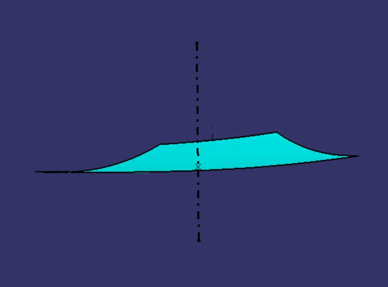
Tooling axis is created by normal to surface method for that first extract a surace and created a poin on it and then using point to direction command create line in y direction as shown below.
3)Draft analysis
Draft analysis is done on class A surface, here all the surface clearing the nominal draft of 3 deg as shown below.
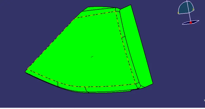
4) class B surface
Class B surface is created by direct offseting of the class A surface to 2.5 mm as per the master section given. while offseting class A some patches will come and we want to work on it to get the proper class B surface.
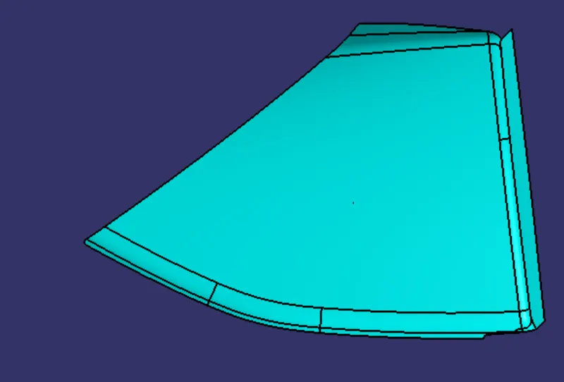
5)Class c surface
Here in the below image the joined class A with class C surface is shown, the class C surface is created by using sweep option with reference to class A surface by giving reference to the surface comand and with draft direction command.
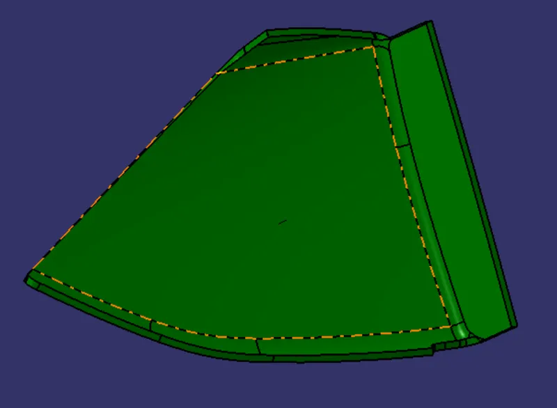
6)Create closed body
Closed body is created by trimming the class B surface and the joined class A and C surface. after creating the closed body check whether there is any gap or boundary exist using boundary tool.After that create solid body by using close surface method.
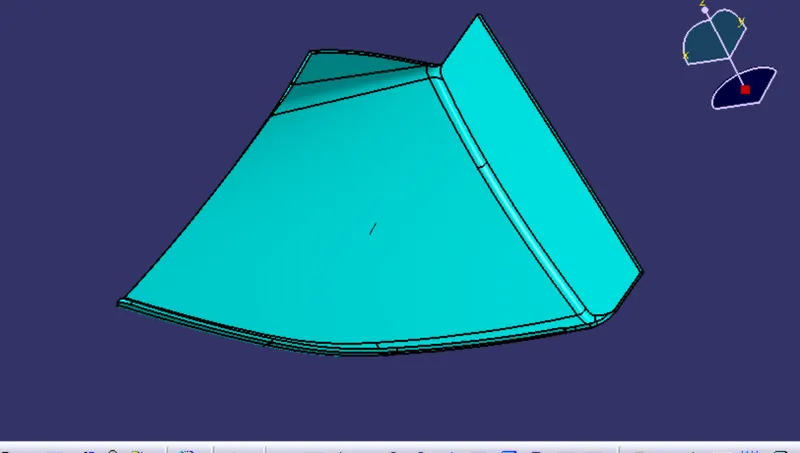
7)Draft analysis
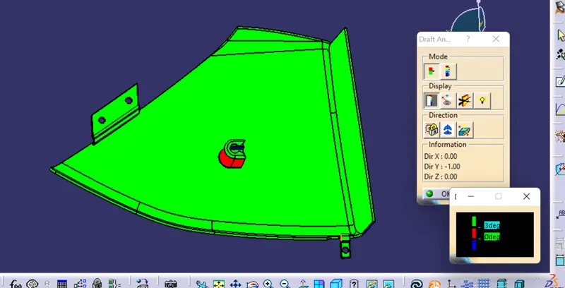
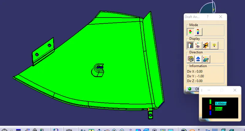
After the creation of solid body perform the draft analysis,here draft analysis is done with two values one for the main part body and one for the attachment features. For main body draft of 3 is given and it is clearing and for dog house draft of 1.5 given for outer surface and it is also clearing by 1.49 deg.
BOTTLE HOLDER
1) Class A surface
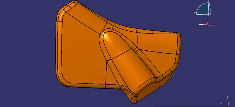
Here the given surface is the class A surface, publish the class A surface
2) Creation of tooling axis
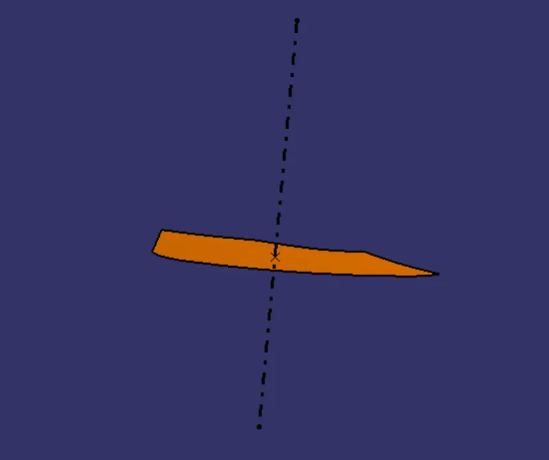
Tooling axis is created by normal to surface method for that first extract a surace and created a poin on it and then using point to direction command create line in y direction as shown below.
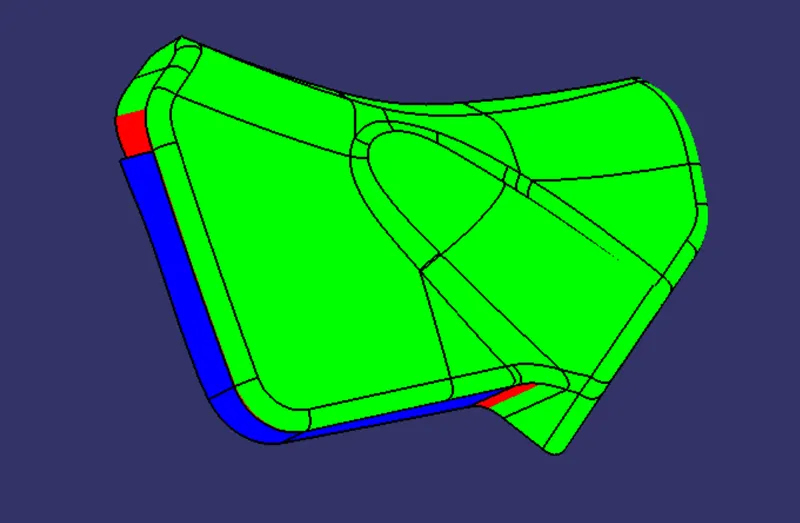
3)Draft analysis
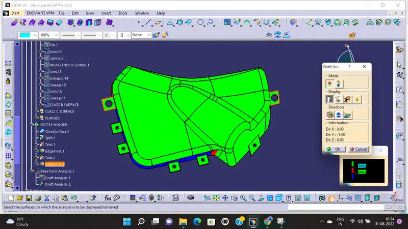
First draft analysis is performed on the class A . some portion of the class A is not clearing the draft as shown in the image below, we dont have the provision to change the class A surface so we move with the surface. This is the problem of class A surface.
4) class B surface
Class B surface is created by direct offseting of the class A surface to 2.5 mm as per the master section given. while offseting class A some patches will come and we want to work on it to get the proper class B surface.
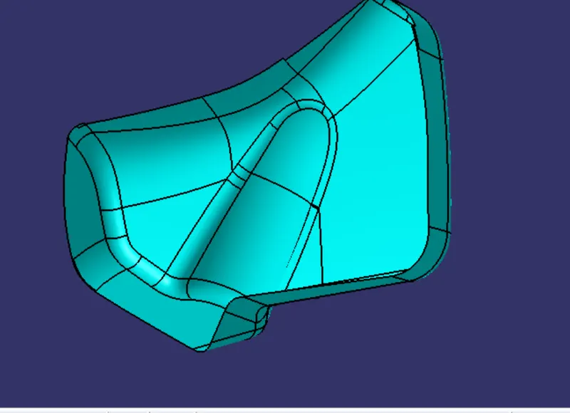
5)Class c surface
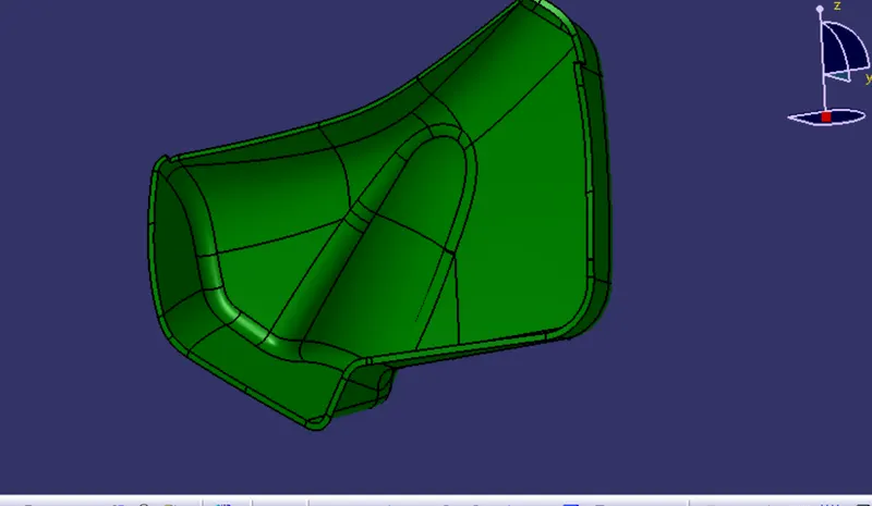
Here in the below image the joined class A with class C surface is shown, the class C surface is created by using sweep option with reference to class A surface by giving reference to the surface comand and with draft direction command.
6)Create closed body
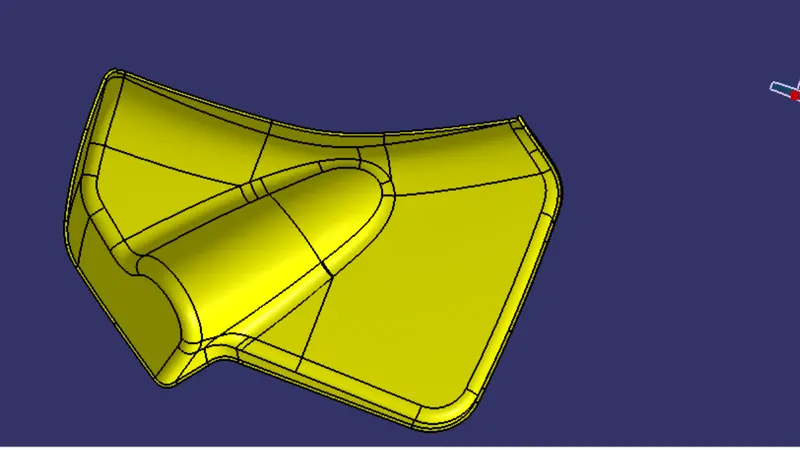
Closed body is created by trimming the class B surface and the joined class A and C surface. after creating the closed body check whether there is any gap or boundary exist using boundary tool.After that create solid body by using close surface method.
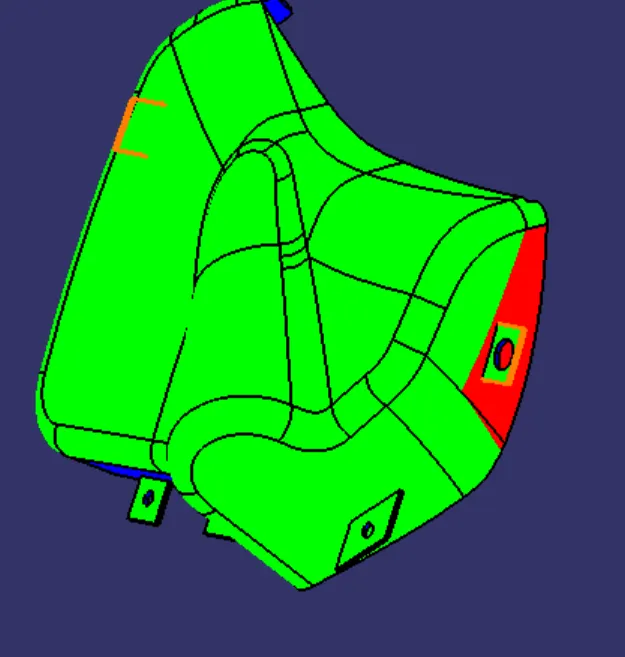
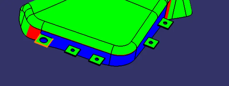
7)Draft analysis
After the creation of solid body perform the draft analysis, here also some portions are not clearing the draft this is because of the class A surface. the portions that are not clearing are also mentioned below.
CREATION OF ATTACHMENT FEATURES
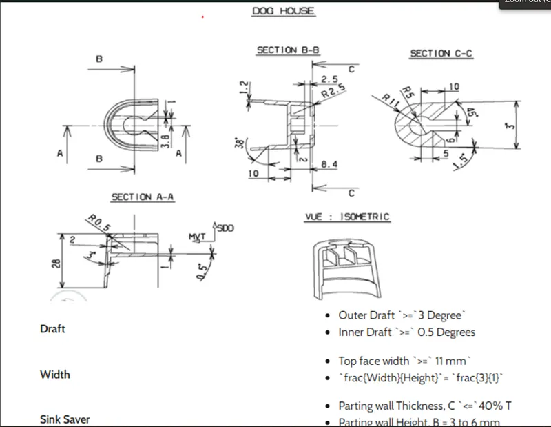
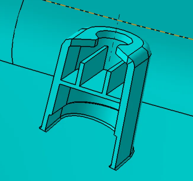
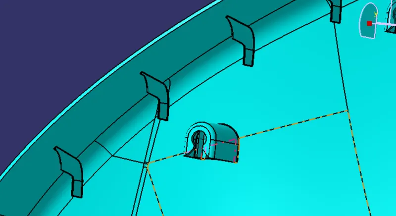
- DOG HOUSE - Dog house is created by using the given drawing as input for design process by following the industrial standards, the drawing of dog house is as shown below. .
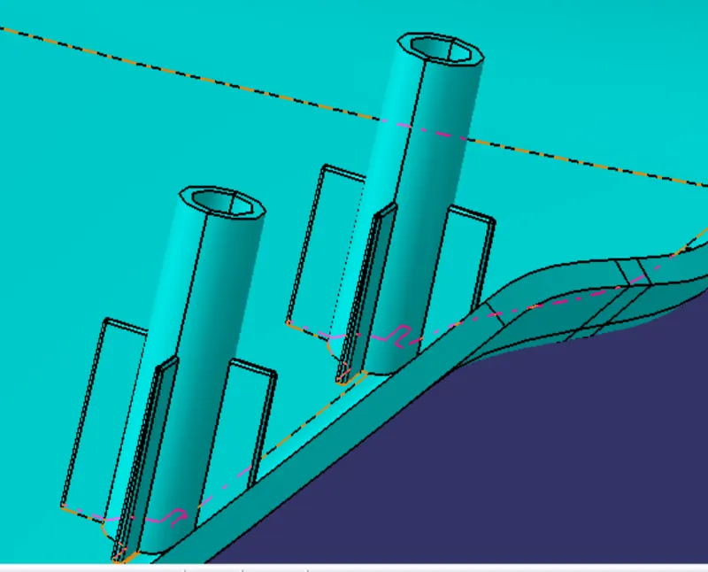
- HEAT STAKES -Heat stakes as created as per the given master sections and following the industrial standards and the design rule. Draft given is 0.5 deg and fillet radius of .25deg are given and for support ribs are also given since the height of heat stakes are high , the chance of failure of heat stakes are high so ribs are also given.
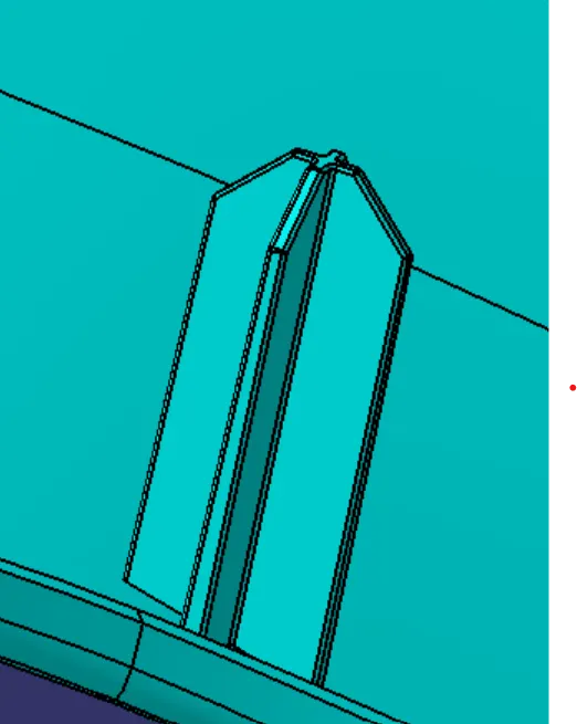
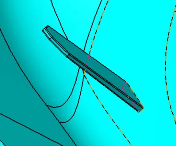
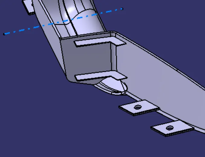
- LOCATORS - Locators are also created to make the assembly more easy, both 2 way and 4 way are provided with industrial standards of min draft 0.5 deg and fillet radius of .3 deg.
- RIBS - Ribs are also created in door arm rest and door lower substrate for the support purpose, ribs are created by following the industrial standards and desaign rule. draft of 0.5 deg and fillet radius of .25 deg are given.
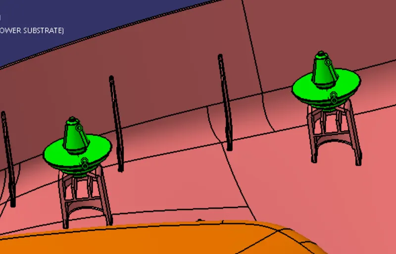
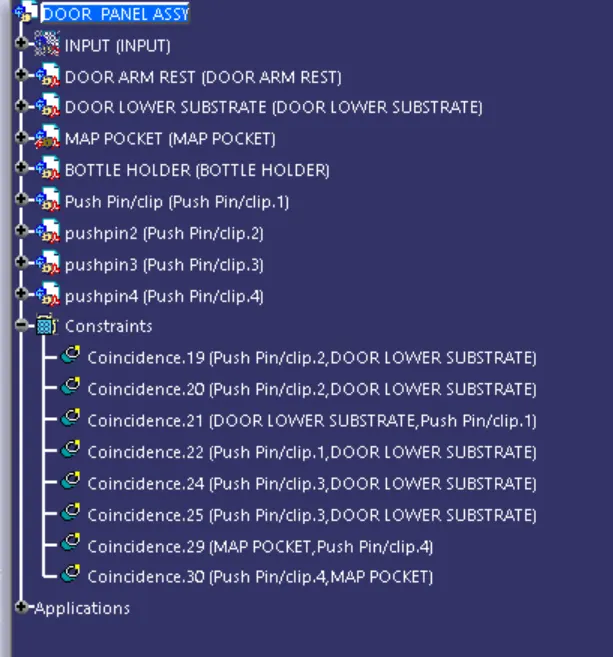
ASSEMBLY Here the given push pins are assembled in the Dog house, the push pins are used for joining one component to another, here i have used 4 push pins for the 4 dog house .
FINAL ASSEMBLED IMAGE