Week 11 - Final project
Object :- Create the product file from the given Class A data with all the parts separated out and create the tooling direction for all the parts. Create the solid bodies by making proper class B and class C surface and apart from this create the flange and engineering features by following master section. Create the feature for final join operation to be performed with dog houses and heat stakes.
-
Consider the thickness of the component 2.5 mm.
Introduction :- This project is done on CATIA software. This software is different from other. It is easy to designing for surface modelling. Its have more accuracy than other. CATIA is an acronym for Computer Aided Three-dimensional Interactive Application. It is one of the leading 3D software used by organizations in multiple industries ranging from aerospace, automobile to consumer products.
Class A Surface :-
In automotive design application Class A Surfaces are created on all visible exterior surfaces (ex; body panels, bumper, grill, lights etc.) and all visible surfaces of see-touch & feel parts in interior (ex: Dashboard, seats, door pads etc.). This can also include beauty covers in the engine compartment, mud flaps, trunk panels and carpeting. This surface has 0 mm thickness.
Given Class A Surface
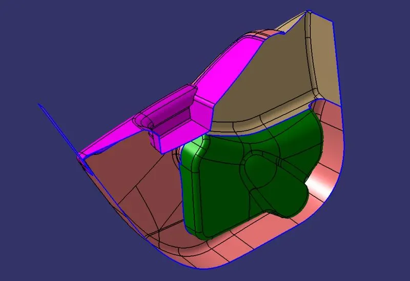
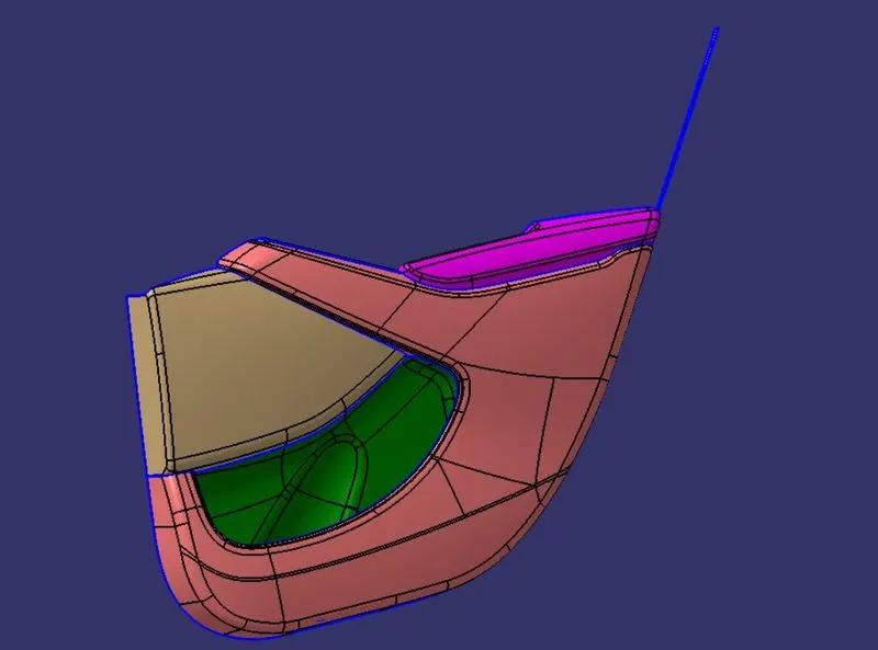
Tooling Axis :-
Tooling axis or tooling direction is main consideration for plastic part and mold parts because it defines movement of mold part and possibility of plastic part to come-out from mold part (Core and Cavity). In Molding machine arrangement is given to open the mold along a direction which is known as Tooling Direction. The mold is built from two separate halves (Core and Cavity) and tooling direction basically define the direction of mold pulls apart. Tooling direction is known as primary direction.
- I have created a seperate tooling direction for each part keeping in mind for better draft analysis.
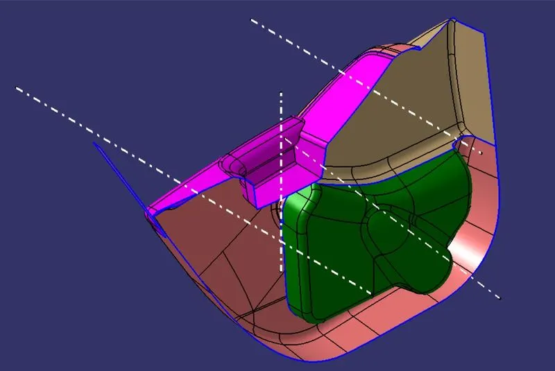
Class B Surface :- The surface which is back side of Class A surface is called Class B Surface. Mostly it not visible. It is created with the help of Class A surface with some distance (thickness) like 2mm, 3mm etc.
- Here I created Class B Surface on 2.5mm from Class A Surface.
Class C Surface :- The Class C surface is the side part of a class A and B surface that is permanently covered by another part.
Master Section of Engineering features :-
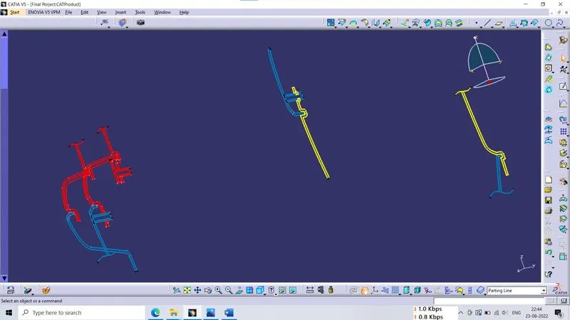
Solid Bodies :- I have created class B and C surface with the help of class A surface and by the join and trim command I made a closed surface and finally I created the solid bodies with the help of closed surface. Apart from this I created the engineering features like Dog House, Heat Steaks and Ribs.
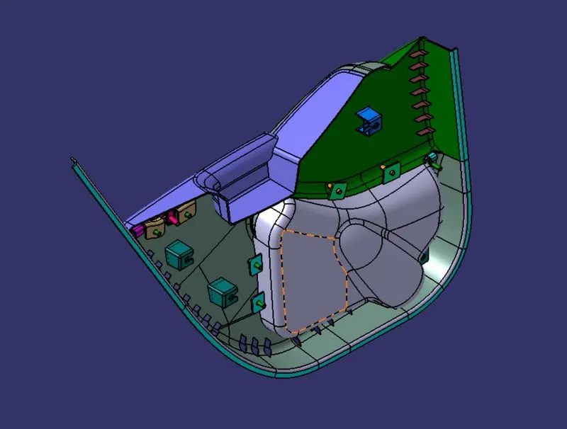
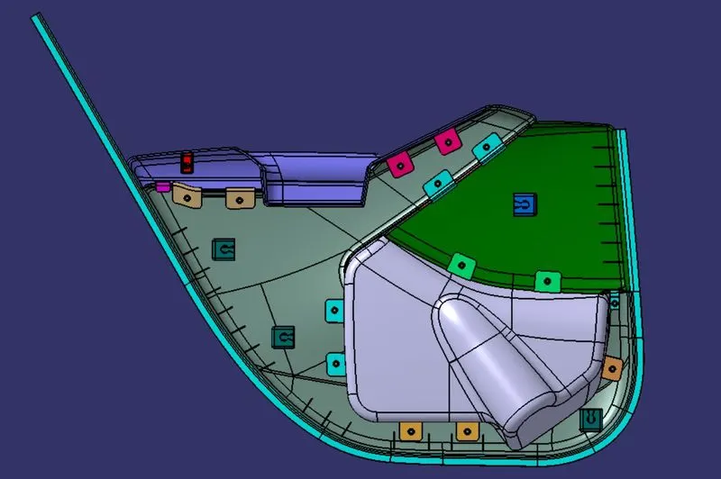
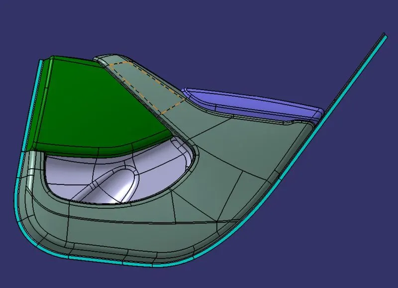
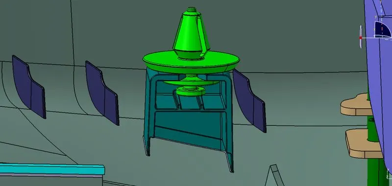
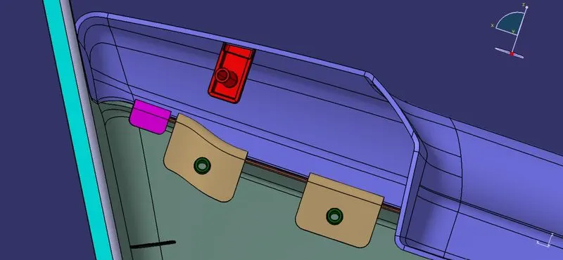
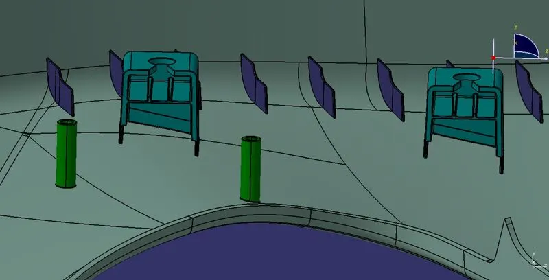
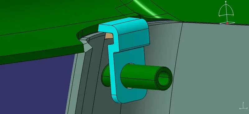
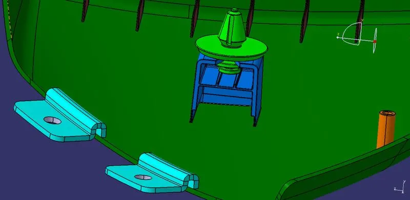
Dog House :- Dog Houses used in automotive interior and exterior plastic trim. There is no such thing, different types of doghouses. Dog House is a b side feature used for assembly fixation (or to increase the height of any features) generally with biw cut-out, with a plastic clip on it. Some times featues like locator, snaps, ect will be fecilitated on dog house, because if there height is too much, the feature will fail. So by doing that, features height is decreased and strength increased. And, Dog House is used for different purpose in different locations depending on situations.
Designing Rules For Dog House :-
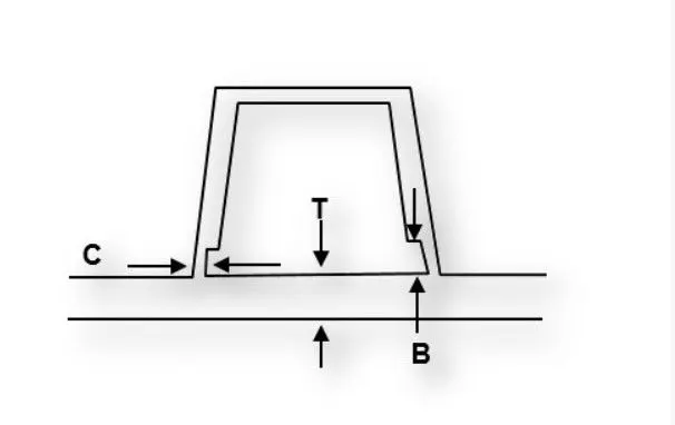
In above figure you can see many nomenclature of alphabet. Here I would like to tell that
- T is the value of thickness of component
- C is the dog house wall thickness, it should be 40% or less than the main wall stock (T)
- B is the height of the wall thickness, it should be between 3.0 mm - 6.0 mm.
Draft Analysis of Dog House :-
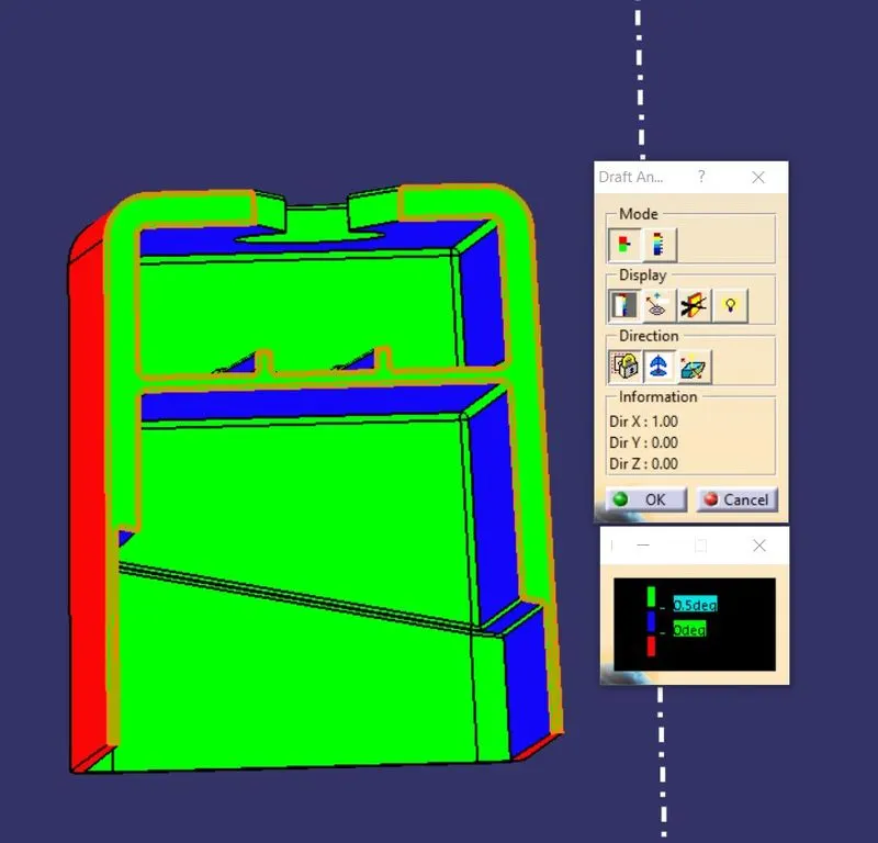
Here I have given 0.5 degree draft analysis. You can see that all internal area are green. This mean OK.
Rib Design :- Ribs provide a means to economical stiffness and strength in molded parts without increasing overall thickness. They also facilitate
- Locating and arresting components of an assembly,
- Providing alignment in mating parts,
- Acting as stops or guides for mechanisms.
Proper Rib design involves many issues which is consider carefully when designing-
- Thickness
- Height
- Location
- Quantity
- Manufacturability
Guidelines for Ribs on Show Surfaces
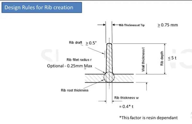
- Draft - 0.5 degree per side minimum
- Thickness - Typically 40% wall thickness
- Height ≤ 5 x wall thickness
- Spacing - 3:1-steel hieght / width ratio maximum
- Thickness at the top ≥ 0.75mm
- Optional Radius - 0.25mm maximum
- Rib root thickness should be under deviation of +-30% from the wall thickness
- Design Suggestions
Ribs should be spaced so that the steel between the ribs is at a
- Height / width ratio
- 3:1 steel
- 2:1 is preferred
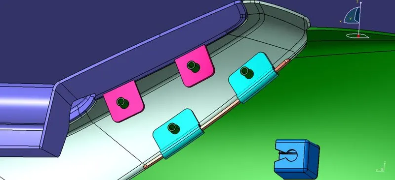
Heat Staking :- Heat Staking is a joining technology to join two or more parts together where at least one is made out of plastic. The process is used to melt and deform the plastic material using heat and force at a set process time.
Draft Analysis :-
The Draft Analysis allows the user to easily analyze a part for proper draft angle. A Draft Angle describes the amount of taper for molded or cast parts perpendicular to the parting line. Draft Analysis is applicable for 3D part models. To create a draft analysis for any 3D part file, the user needs to select part/surface and select the pull direction. You can change the pull direction.
Draft Analysis of Solid Bodies In CATIA :- It provides colour based identification. With the help of this we can easily find that which surface is in clear and which is in stuck by colour changing. Here I give the draft angle 3 degree. The result in colour based that the surface which green (means draft angle > 3 degree) is right. And where the colour is blue mean draft angle is 3 degree to 0 degree if this surface area is low then you can go. If you find red colour zone then it means draft angle is less than 0 degree. Then you will have to create tooling axis by another way if possible, otherwise you can say your design engineer to correct for designing.
- Door Arm rest
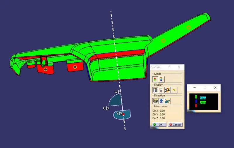
- Lower Substrate
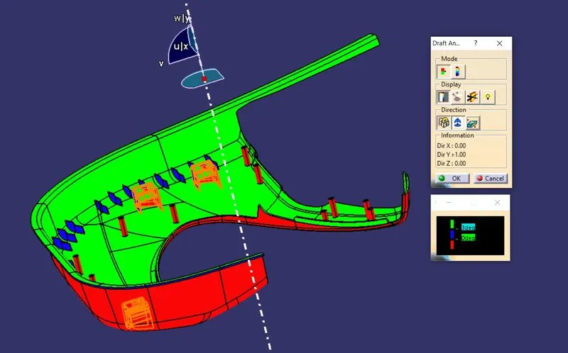
- Upper Map
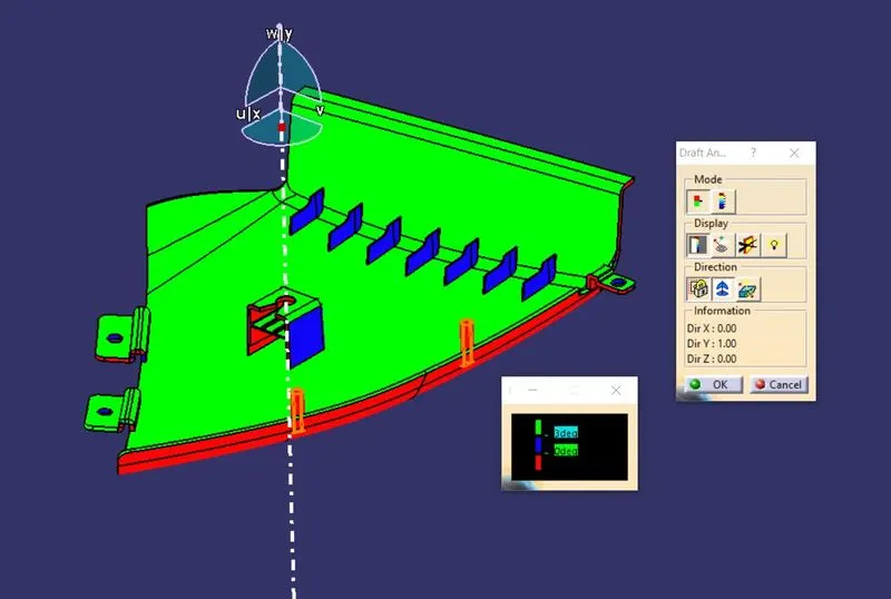
- Bottle Holder
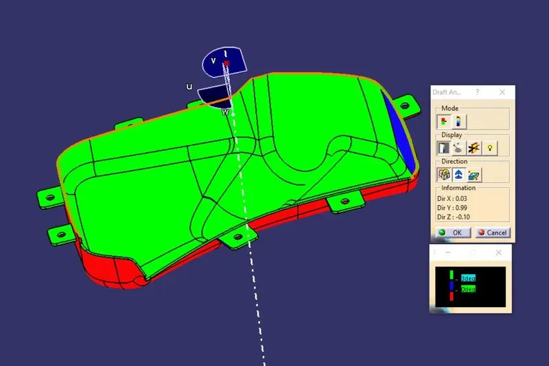
Note :- You are seeing that heat steak surface is in red colour zone because when I use sleeve ejection, there is no need to draft.
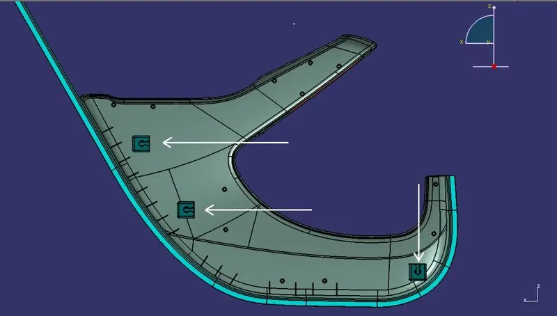
Tooling Feasibility :- Tooling fesibility is like how to work my extra toolig operation such as tooling for Dog house, Heat steak, Ribs etc. Here I want to say that every tooling operation is working perfectly smooth or not. If it would be stucking by other part then we need to redesign and rearrange. In below figure we can see every action have space for tooling action.
Push Pin :-
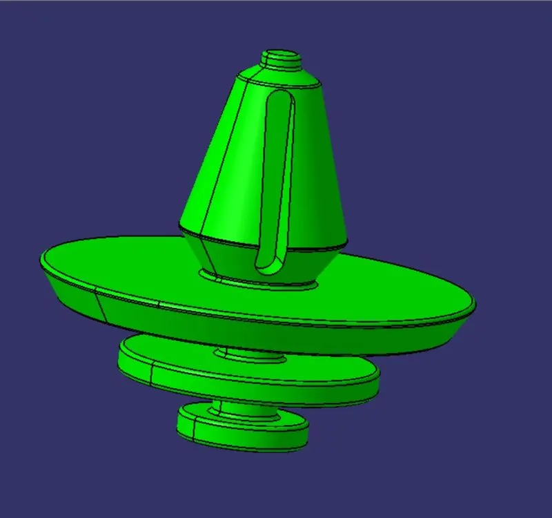
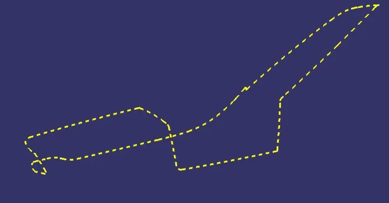
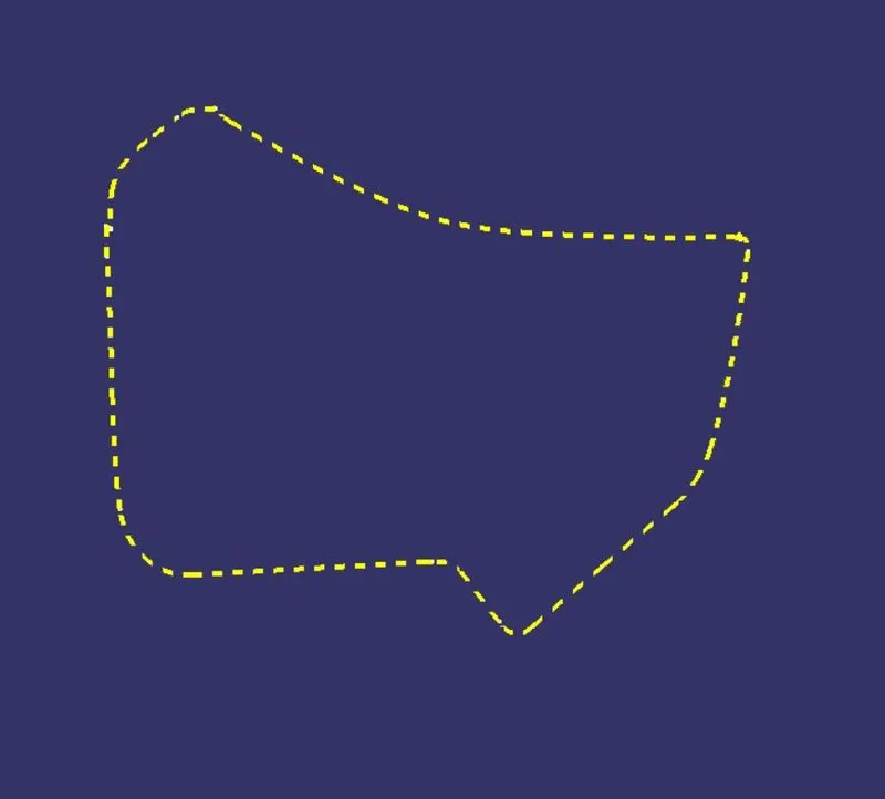
Parting Line and Parting Surface :- Parting line is the line where parting surface and part meets whereas parting surface is the surface that seperate the mold block into two parts- the core and the cavity. In other words these two parts are pressed tightly and formed a sealed hollow to avoid the melt flow leakage and maintane certain holding pressure, the pressed surface is called parting surface.
- Door Arm Rest
- Lower Substrate

- Upper Map

- Bottle Holder
Conclusion :- In this project we learnt that how to make the part in assembly file and how to do fine finishing. This Challange remained very motivational that's because I learnt different type of command that how to do finishing, how to make the part by master section ect.
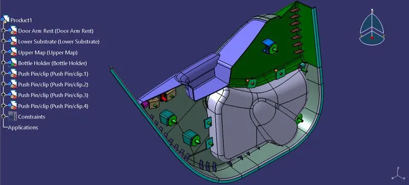
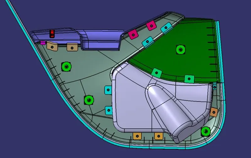
Some Images Of Assembly