Week 11 - Final project
AIM: Development of a Door Trim panel using the given Class-A Surfaces along with the master sections.
OBJECTIVES:
- Create a tooling axis for the given Class A.
- Create Class B and Class C surfaces from the given Class A using the given master sections.
- Create a closed body out of it.
- Perform draft analysis on the given Class A Surface and then the final component.
- Create the mounting features as per design guidelines in the industry and with master sections.
- Creation of parting lines and check tooling feasibility.
- Create necessary B-side features like Push pin, dog house, heat stake, etc.
- Finally, all the surfaces have been assembled together into one CATproduct.
INTRODUCTION:
In this project, we are designing a Door Trim panel from Class-A surfaces using the Catia software, from that we create a Class-B surface with a thickness mentioned in the master section. And Class C is also created using both Class A & B. Draft analysis is also conducted with a minimum of 3 degrees as standard. Make sure that the surface model is completely closed before converting into solid. Do this for all four surfaces and assemble it into a single final component.
Draft
In engineering, the draft is the amount of taper for molded or cast parts perpendicular to the parting line. It can be measured in degrees or mm/mm (in/in)
- Drafts (or taper) in a mold, facilitate part removal from the mold. The amount of draft angle depends on the depth of the part in the mold, and its required end-use function.
- The draft is in the offset angle in a direction parallel to the mold opening and closing.
- It is best to allow for as much draft as possible for easy release from the mold. The minimum taper angle is 0.5 to 1 degree but 3 degrees is a widely accepted norm.
- The mold parting line can be relocated to split the draft in order to minimize it. If no draft is acceptable due to design considerations, then a side action may be required at a greater expense in tooling.
Draft Analysis
Displays a color gradient on the faces of selected bodies to help evaluate the manufacturability of your design. Select the bodies to evaluate and the axis to define the direction. Use the options to refine the gradient display. In Catia, we use the feature draft analysis tool for this.
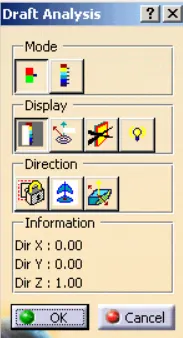
Tooling Axis
It is the direction in which the mold or core and cavity open is the tooling axis
Given Class A Surfaces with master section
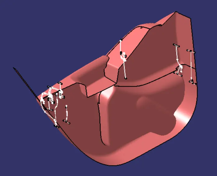
Heat Stake
Heat staking also known as thermoplastic staking is the process of joining two dissimilar materials together. In heat staking, we use local heating and cooling to raise the temperature of plastic components and allow plastic reforming to be carried out. This reform can be used in a wide variety of applications.
Dog House
Dog House is a B-side feature used for assembly fixation (or to increase the height of any features) generally with biw cut-out, with a plastic clip on it. some times features like locator, snaps, etc will be facilitated on the doghouse, because if their height is too much, the feature will fail.
Push Pin
These rivet fasteners are made of nylon material, suitable for car use. Cars are good accessories, commonly used for fitting side skirts, bumpers, and other trim. These clips are suitable for firmly holding anything within a fit diameter hole.
PROCEDURE:
1. Arm Rest
- Creation of tooling axis
On this surface, we are going with the trial and error method by selecting a random point on the surface. For that, I take the center of the flat surface as a reference point as shown below. Then extend it in the Z direction, ie taken as the tooling axis for this surface.
In this design, the bisector method is more difficult compared to this method.
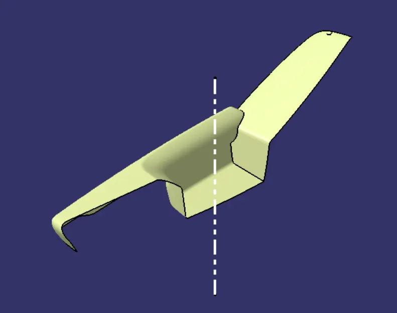
- Draft Analysis of Class-A
Draft analysis is conducted with a limiting value of 3 degrees. By this, we confirm whether our trial and error method for selecting the tooling axis is correct or not.
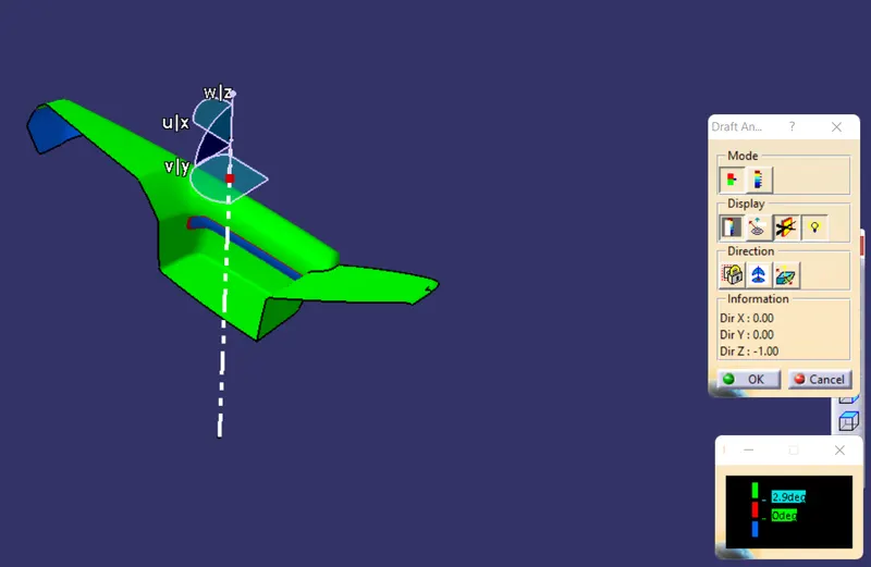
Some portions are not clearing the 3 degrees (taken as 2.9 degrees in analysis), in real case we should report it to the styling team. Now we ignore this and move forward.
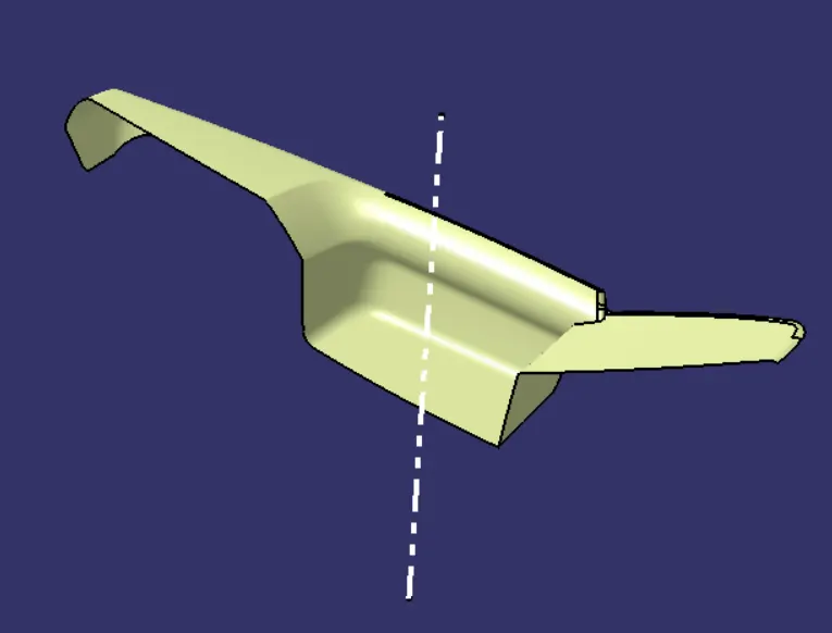
- Class B
In this, the Class-A surface is offset with a nominal thickness which can be referred to from the master section, but we may face some gaps occur. Close the gaps using various operations and join into a single surface.
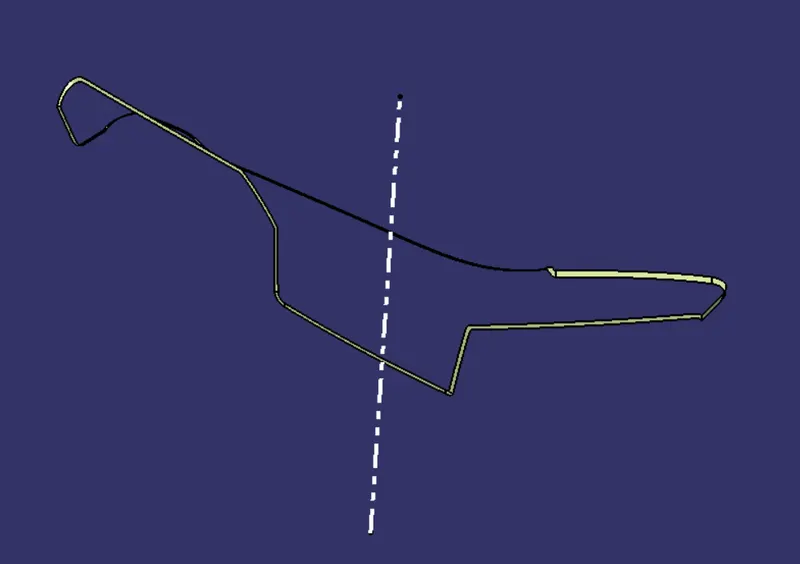
- Class C
Class C Surface is the connection surface of Class-A and B.
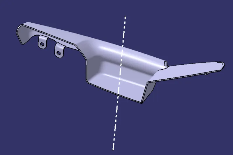
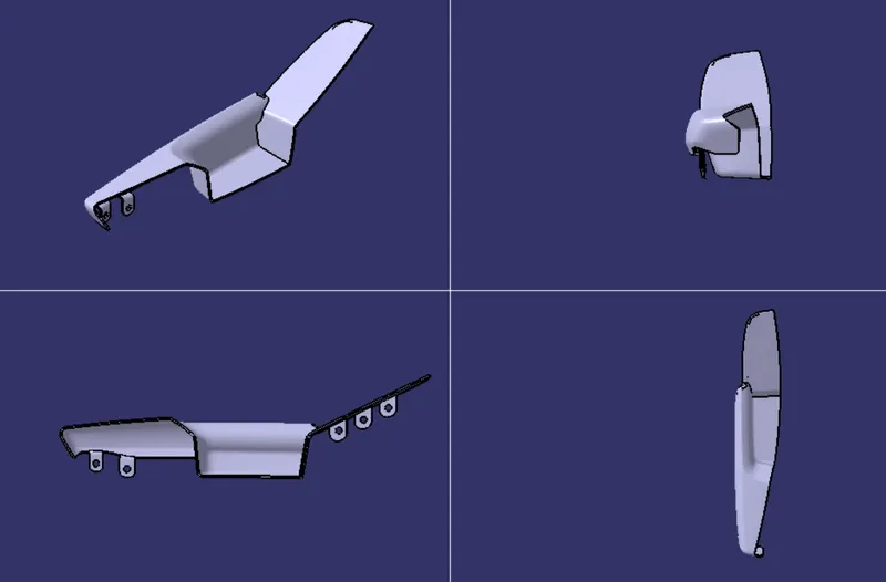
- Solid Arm Rest
In this, we add flanges for holding heat stakes that are located in the lower substrate for the heat staking process. Flanges are designed with respect to the master section.
- Solid body with parting line
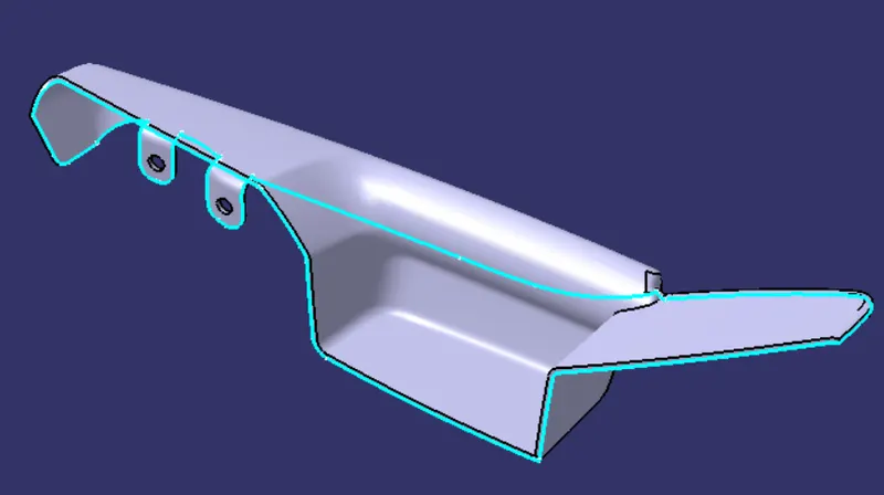
- Draft Analysis of the Solid Arm Rest (Final Component)
- Draft Analysis wrt Main Tooling Axis
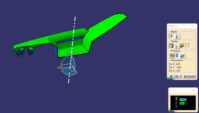
- Draft Analysis of the holes (in the flange)
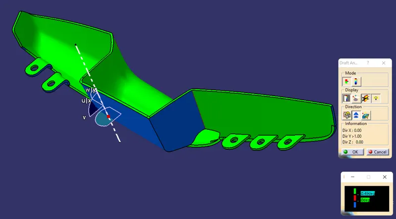
Holes are clearing the minimum 0.49 degrees draft in all the flanges
2. Map Pocket
- Creation of tooling axis
On this surface, we are going with the trial and error method by selecting a random point on the surface. For that, I take the center of the flat surface as a reference point as shown below. Then extend it in the Y direction, ie taken as the tooling axis for this surface.
In this design, the bisector method is more difficult compared to this method.
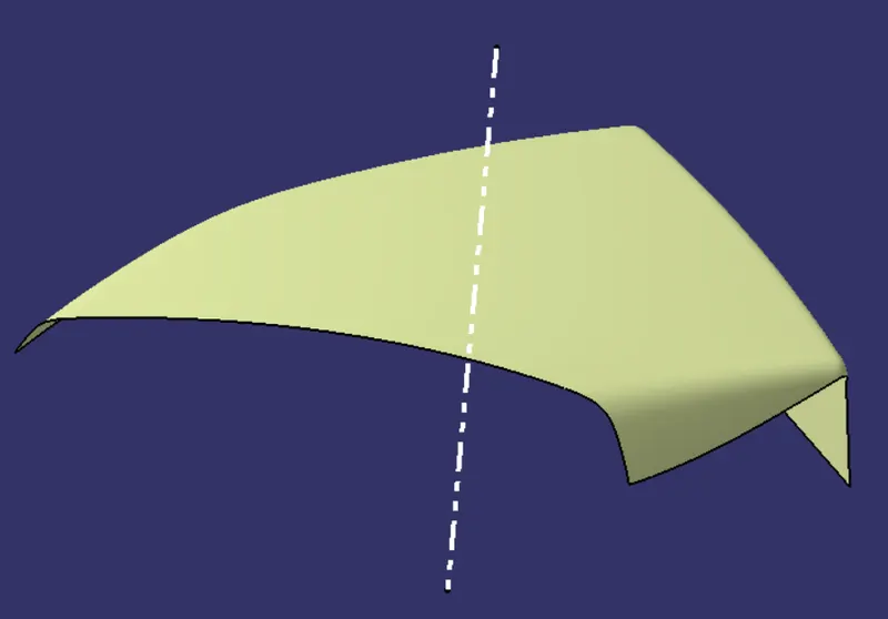
- Draft Analysis of Class A
Draft analysis is conducted with a limiting value of 3 degrees. By this, we confirm whether our trial and error method for selecting the tooling axis is correct or not.
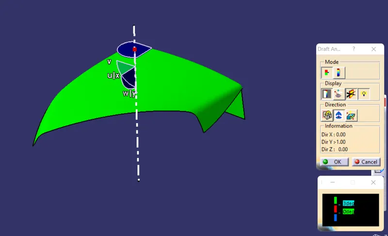
The Class A surface is clearing the minimum draft of 3 degrees so, the taken main tooling axis is correct.
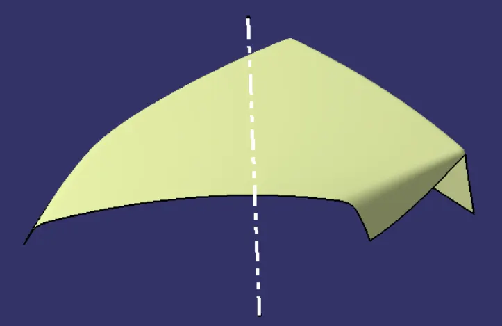
- Class B
In this, the Class-A surface is offset with a nominal thickness which can be referred to from the master section, but we may face some gaps occur. Close the gaps using various operations and join into a single surface.
- Class C
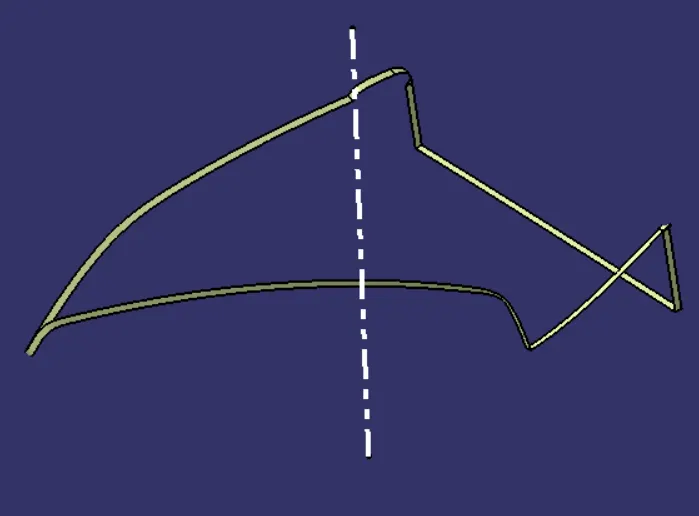
Class C Surface is the connection surface of Class-A and B.
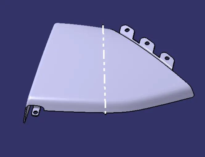
- Solid Map Pocket
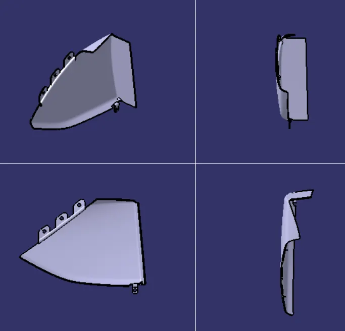
- Solid body with parting line
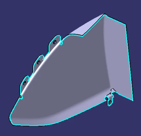
- Draft Analysis for Solid Map Pocket
Draft Analysis of the Final Component
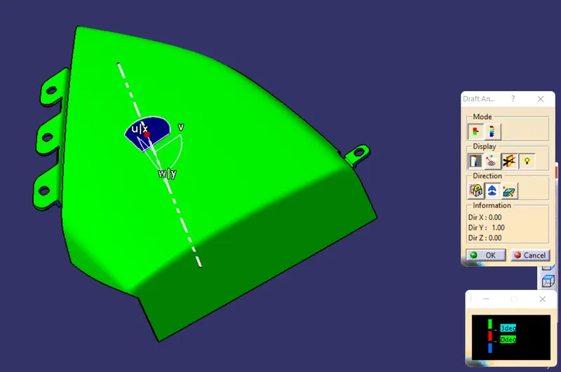
Draft Analysis of the holes (on the flange)
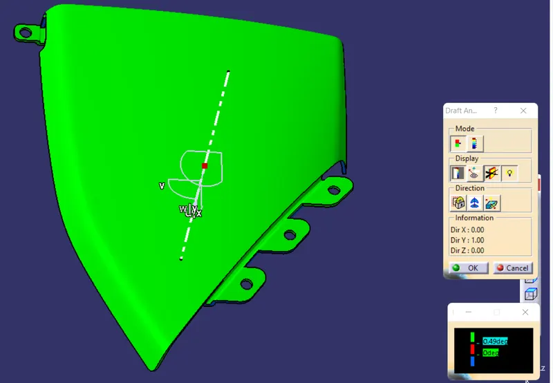
Holes are clearing the minimum 0.49 degrees draft in all the flanges
3. Bottle Holder
- Creation of tooling axis
On this surface, we are going with the trial and error method by selecting a random point on the surface. For that, I take the center of the flat surface as a reference point as shown below. Then extend it in the Y direction, ie taken as the tooling axis for this surface.
In this design, the bisector method is more difficult compared to this method.
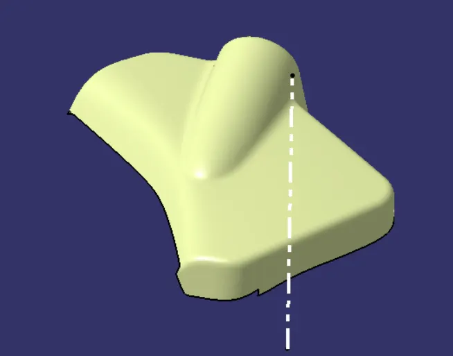
- Draft Analysis of Class A
Draft analysis is conducted with a limiting value of 2.9 degrees. By this, we confirm whether our trial and error method for selecting the tooling axis is correct or not.
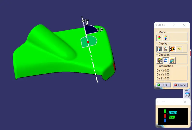
Some portions are not clearing the 3 degrees (taken as 2.9 degrees in analysis), in real case we should report it to the styling team. Now we ignore this and move forward.
- Class B
In this, the Class-A surface is offset with a nominal thickness which can be referred to from the master section, but we may face some gaps occur. Close the gaps using various operations and join into a single surface.
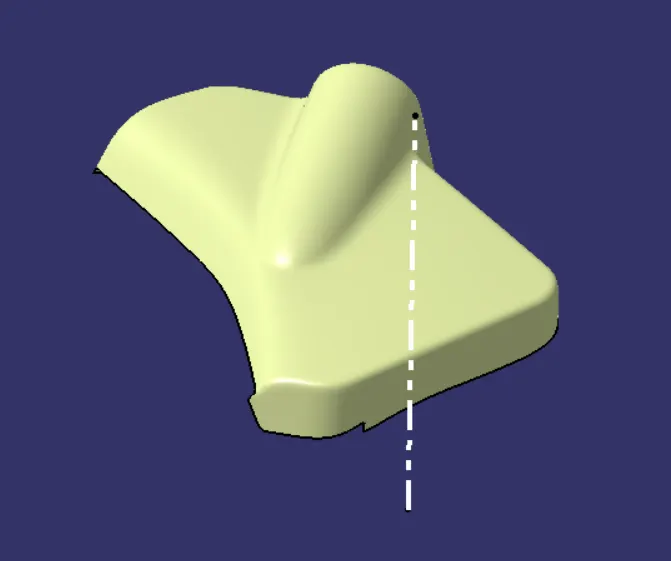
- Class C
Class C Surface is the connection surface of Class-A and B.
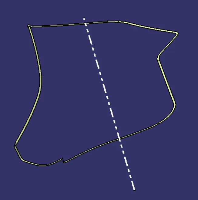
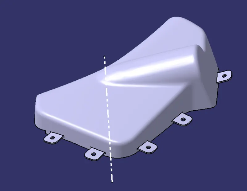
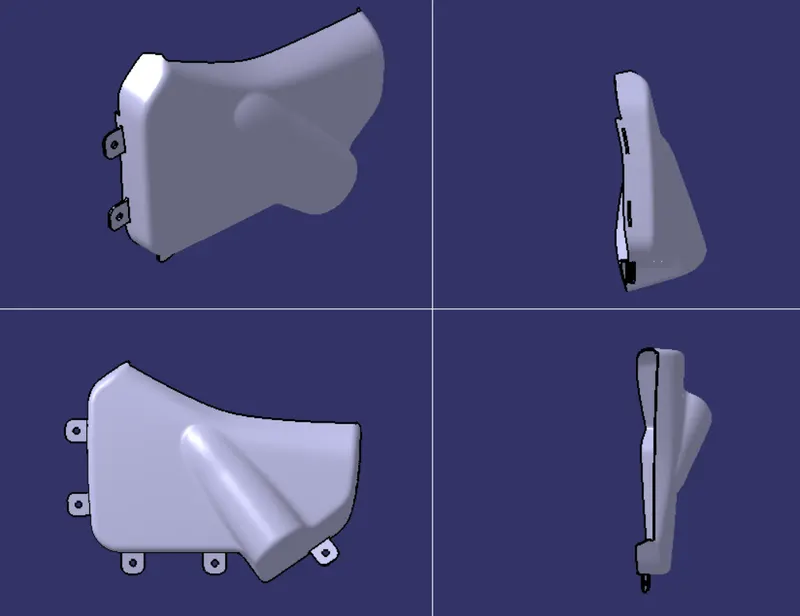
- Solid Bottle Holder
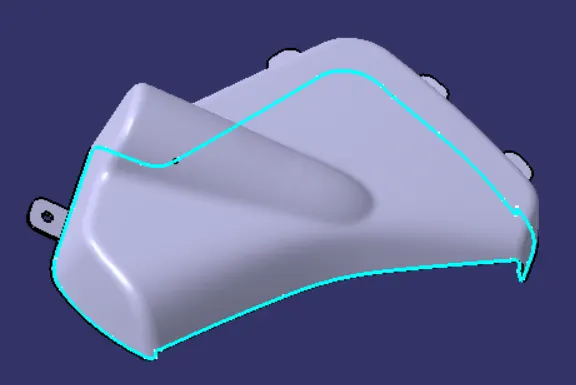
- Solid Body with parting line
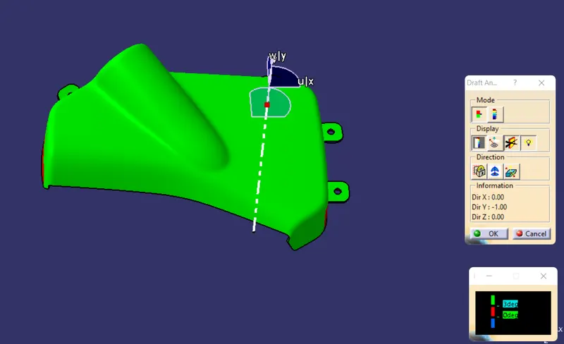
- Draft Analysis for Solid Bottle Holder
Draft Analysis of the Final Component
Draft Analysis of the holes (on the holes)
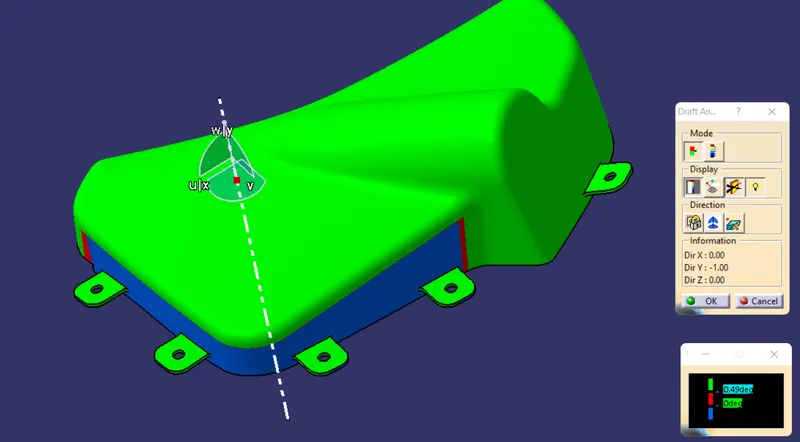
Holes are clearing the minimum 0.49 degrees draft in all the flanges
4. Lower Substrate
- Creation of tooling axis
On this surface, we are going with the trial and error method by selecting a random point on the surface. For that, I take the center of the flat surface as a reference point as shown below. Then extend it in the Y direction, ie taken as the tooling axis for this surface.
In this design, the bisector method is more difficult compared to this method.
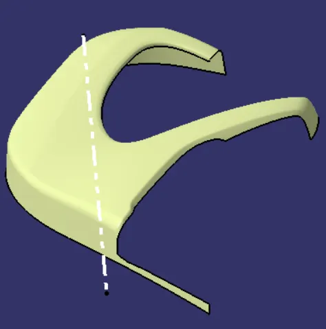
- Draft Analysis of Class A
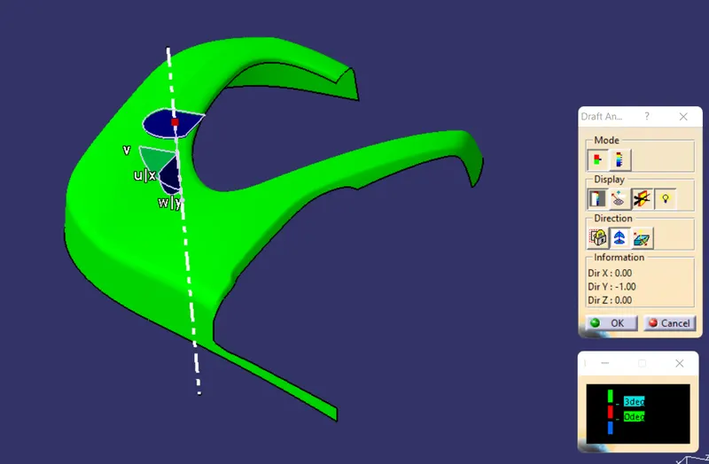
The gven class A is completely clearing the minimum draft of 3 degrees.
- Class B
In this, the Class-A surface is offset with a nominal thickness which can be referred to from the master section, but we may face some gaps occur. Close the gaps using various operations and join into a single surface.
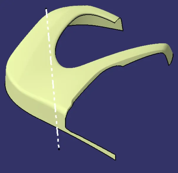
- Class C
Class C Surface is the connection surface of Class-A and B.
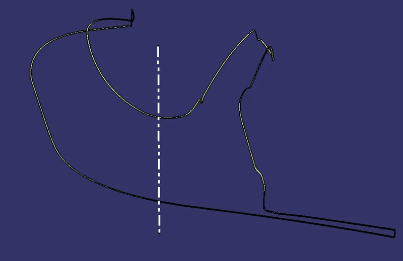
- Dog House
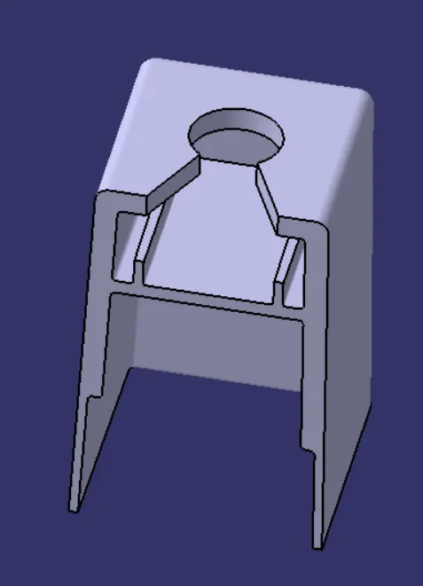
- Heat Stake
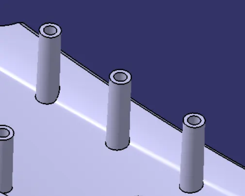
- Solid Lower Substrate
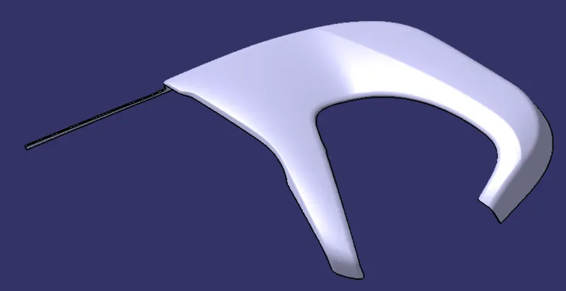
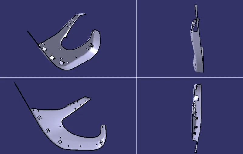
- Solid Body with parting line
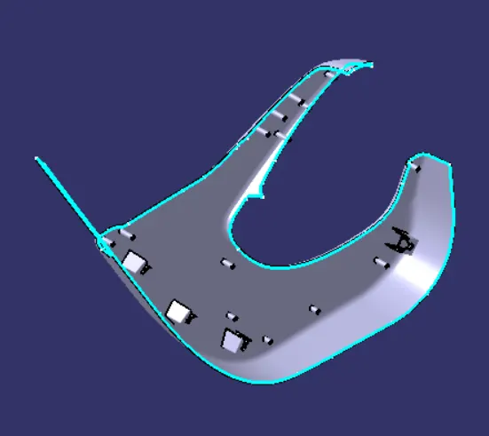
- Draft Analysis for Solid Lower Substrate
Draft Analysis of the Final Component:
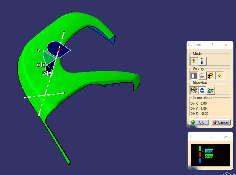
Draft Analysis of the Heat Stake;
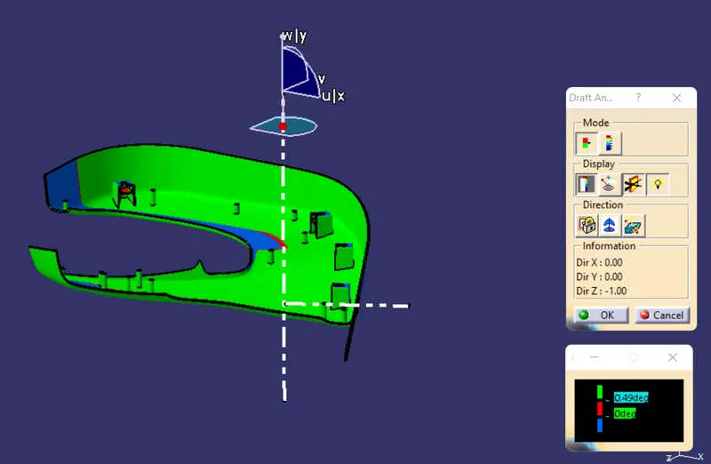
Heat stakes are clearing the minimum 0.49 degrees draft.
Draft Analysis of the Dog House (main tooling axis):
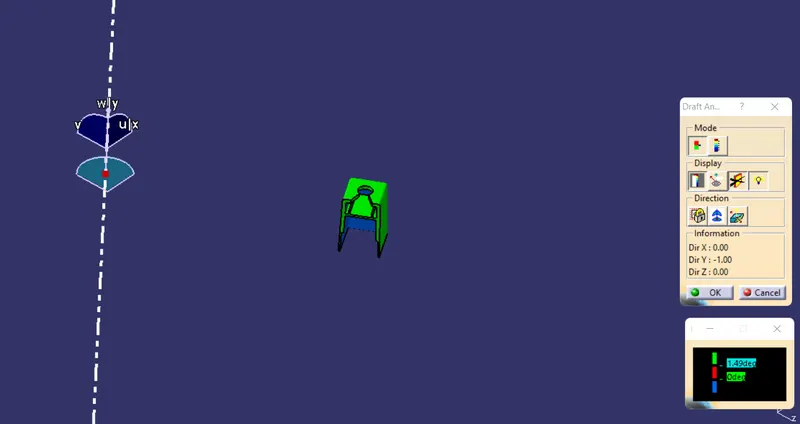
Dog House is clearing the minimum 1.49 degrees draft with the main tooling axis, the above-shown figure is the parent dog house. Similarly there are four dog houses in the lower substrate
Draft Analysis of the Dog House (side core tooling axis):
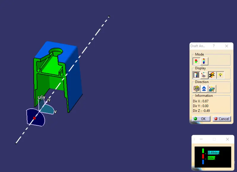
Dog House is clearing the minimum 0.49 degrees draft with the side core axis.
Door Trim panel
Before applying material:
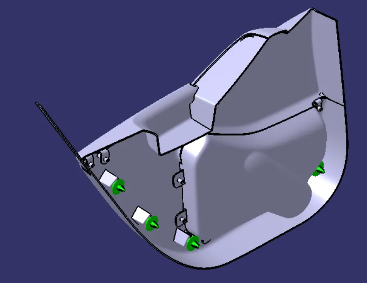
After applying material:
1. Isometric View
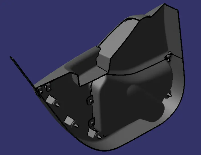
2. Front View
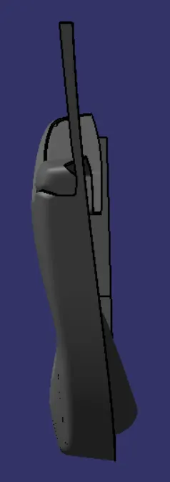
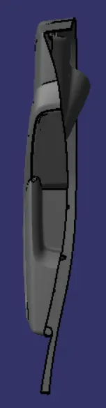
3. Side View
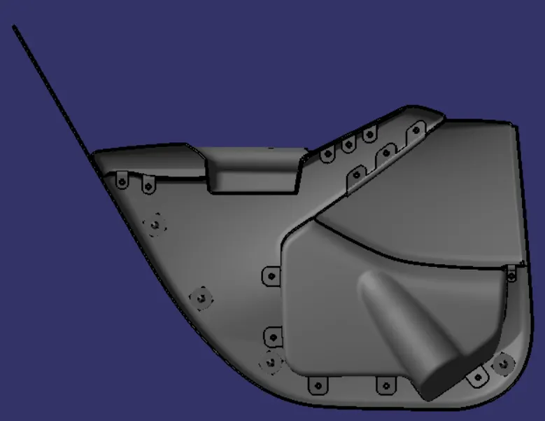
4. Top View
CONCLUSIONS:
Door lower trim panel is created in the assembly workbench using the components arm rest, bottle holder, map pocket, and lower substrate which are created using the surface and part workbench with proper draft. Parting line is also created.
Finally plastic material is applied to the panel.