Week 11 - Final project
AIM:
To design a Door Panel of an Automotive using CATIA V5. Creation of CAD model considering following inputs as like in OEM and tier1 companies.
- a) Class A surface
- b) Nominal thickness : Refer master sections
- c) Attachment strategy :
Find a attachment strategy for the door panel complete work.
Use Push pin with Dog house for Lower substrate – Door panel attachment
Use heat stakes for part to part attachment
OBJECTIVE:
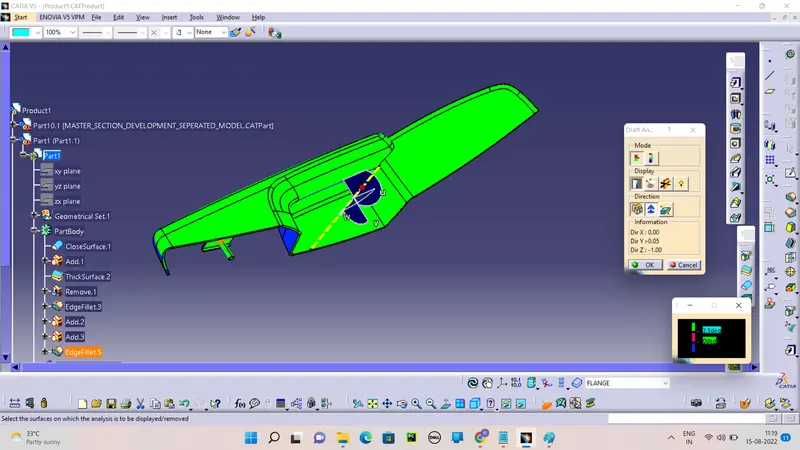
To create an assembly and organize different surfaces of the given class A surface into different parts of the door trim panel. To create a tooling axis and perform a draft analysis on the class A surface of each part.
To create class B, class C surface, and close surface for each part.
To perform draft analysis on the close body of each part.
To create engineering features (Heat stakes, Locators, Dog House) to join the parts of the door trim panel together.
To assemble push pins to the door panel.
INTRODUCTION:
The design of Automotive Interior and Exterior plastic components is called Trims. The plastic components that you see inside the car are Interior.
A door panel, also known as a door card, is an insert that covers the interior components of a vehicle's door. Modern cars often have door cards that are constructed of plastic and incorporate other decorative elements, with injetion molding being the most common method. Other features that add to the vehicle's aesthetic, functionality, and ergonomics are usually included in the door panel. Armrests, s witches, or other controls for the windows and locking mechanism, convenience lights, speakers, storage compartments.
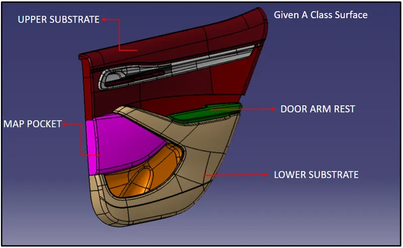
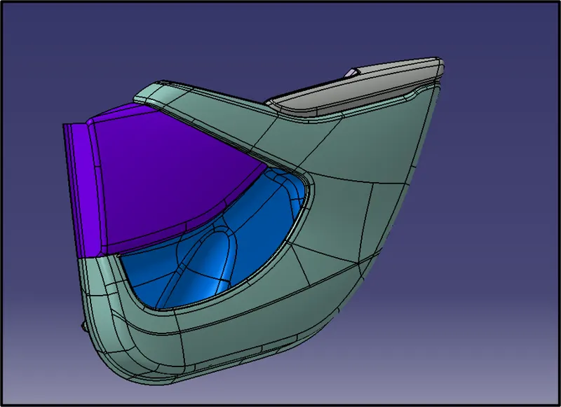
CLASS A SURFACE OF A DOOR PANEL
• Front Side
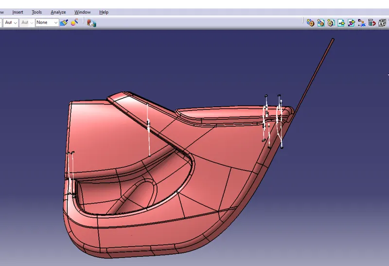
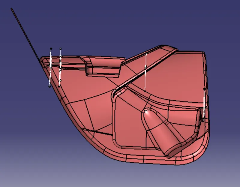
Back Side
CREATION OF AN ASSEMBLY:
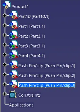
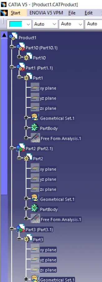
Open the CAD file in product workbench file by Load file command and Open the 4 New Part file and Split it Individually by the copy and paste method.
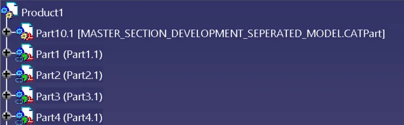
The part names are Door Arm Rest , Map Pocket , Bottel Holder , Lower Substrate. Create the Geometry set for the Master sections.
Create the Solid plastic trim from the Class A Surface to the individually.
1) DOOR ARM REST:
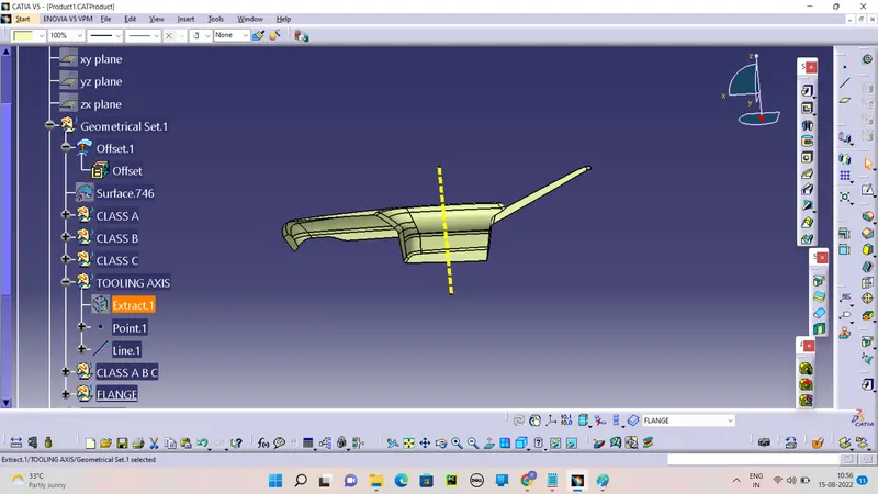
CREATING TOOLING AXIS:
First Extract the sutable surface and create the point on the Surface. Then Create the line by the define line command by the reference of the surface and point.
CREATING THE CLASS B SURFACE:
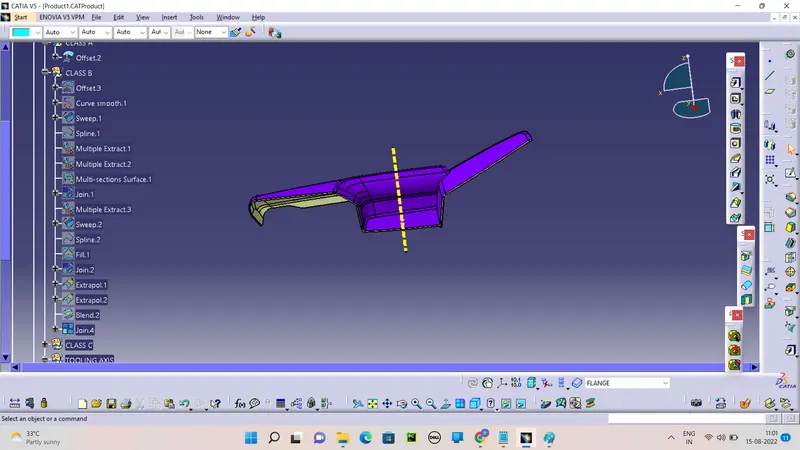
Create the Class B by the Offset of the Class A to 2.5mm guiding of Mater section.
CREATE THE CLASS C:
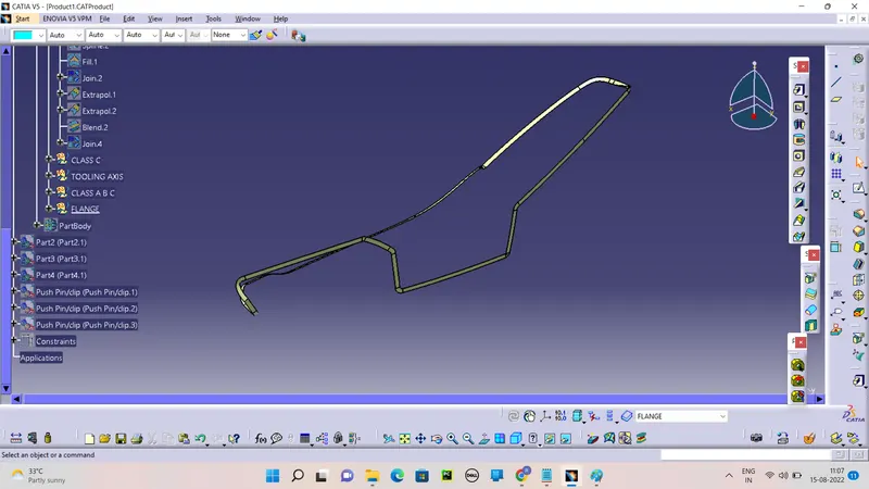
Creating the Class C Surface by the Sweep command using the boundery Extraction and Join with Class A and Trim with Class B Surface. Make the Close view.
CREATING CLOSE VIEW:
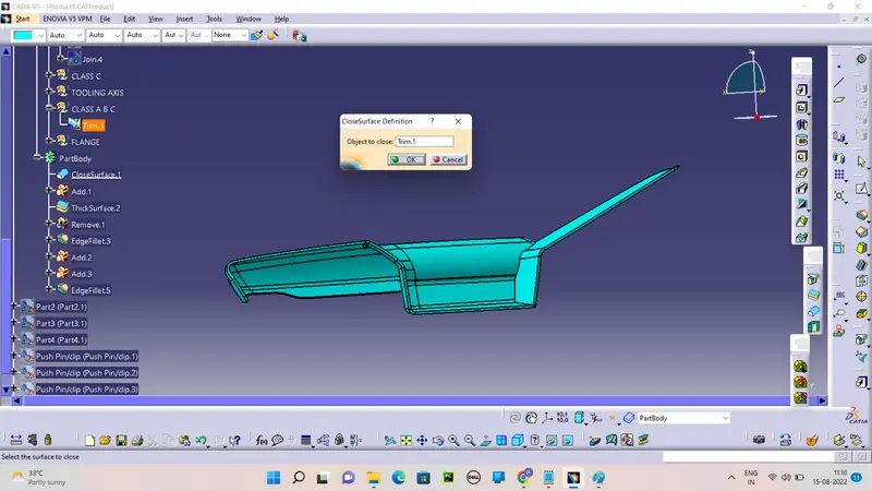
Create the Full Close view by the join and trim command.
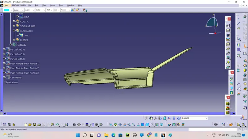
SOLID PLASTIC TRIM:
Define the Part body and create the Solid part by the Close View command.
DRAFT ANALYSIS:
2) LOWER SUBSTRATE:
CREATING TOOLING AXIS:
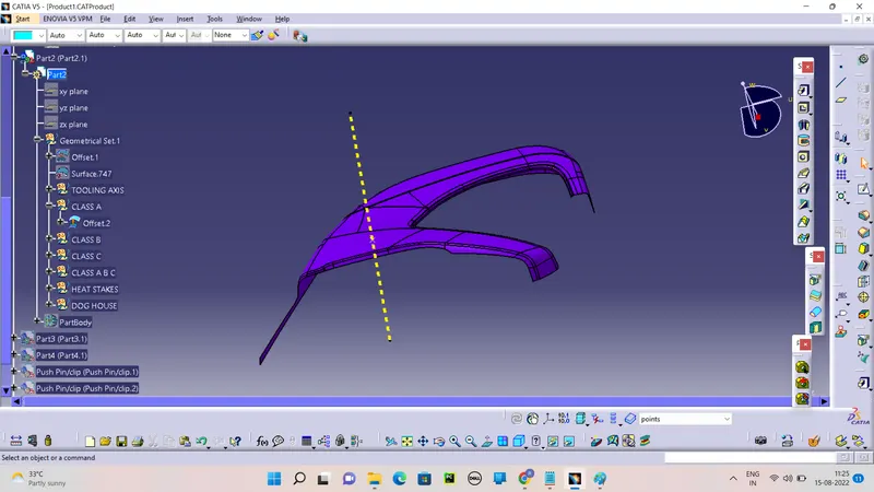
First Extract the sutable surface and create the point on the Surface. Then Create the line by the define line command by the reference of the surface and point.
CREATING THE CLASS B SURFACE:
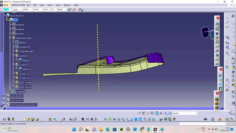
Create the Class B by the Offset of the Class A to 2.5mm guiding of Mater section.
CREATE THE CLASS C:
Creating the Class C Surface by the Sweep command using the boundery Extraction and Join with Class A and Trim with Class B Surface. Make the Close view.
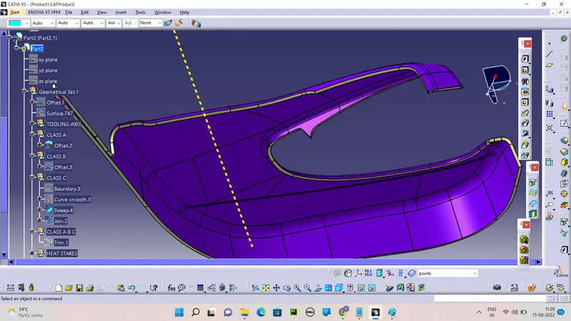
CREATING CLOSE VIEW:
Create the Full Close view by the join and trim command.
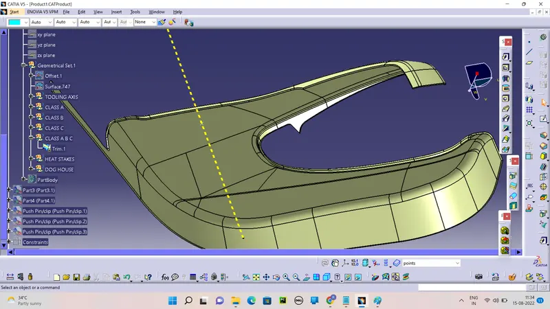
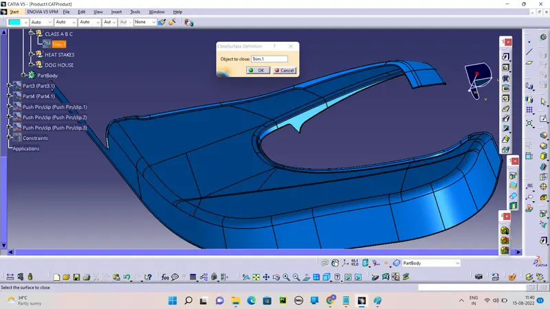
SOLID PLASTIC TRIM:
Define the Part body and create the Solid part by the Close View command.
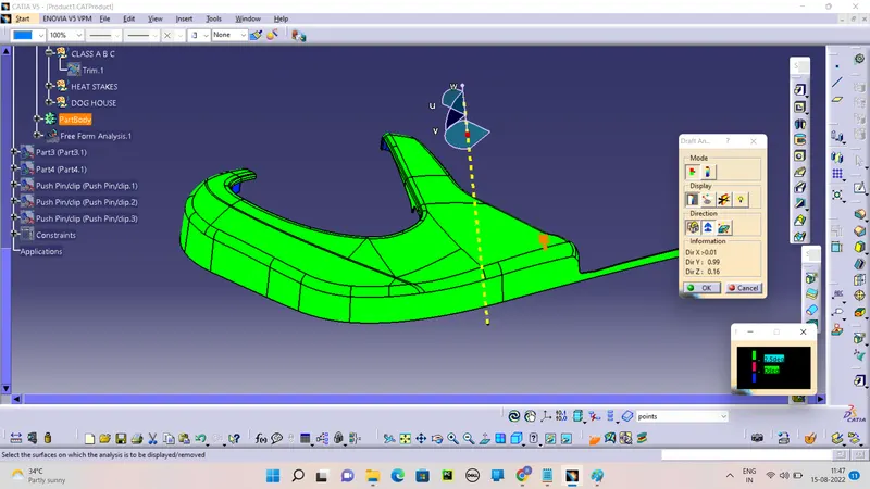
DRAFT ANALYSIS:
3) MAP POCKET:
CREATING TOOLING AXIS:
First Extract the sutable surface and create the point on the Surface. Then Create the line by the define line command by the reference of the surface and point.
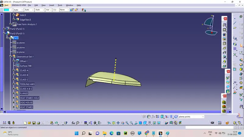
CREATING THE CLASS B SURFACE:
Create the Class B by the Offset of the Class A to 2.5mm guiding of Mater section. Extrapolate the Class B edges for the trim with class A.
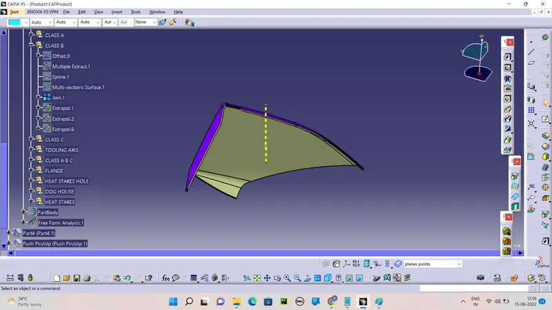
CREATE THE CLASS C:
Creating the Class C Surface by the Sweep command using the boundery Extraction and Join with Class A and Trim with Class B Surface. Make the Close view.
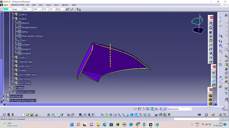
CREATING CLOSE VIEW:
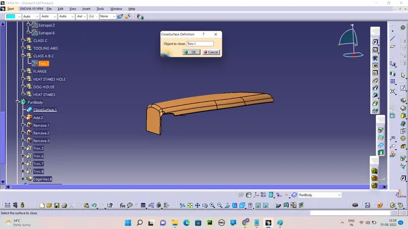
Create the Full Close view by the join and trim command.
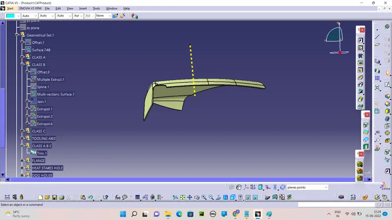
SOLID PLASTIC TRIM:
Define the Part body and create the Solid part by the Close View command.
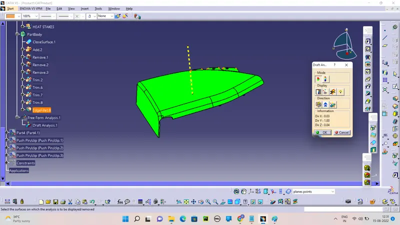
DRAFT ANALYSIS:
4) BOTTLE HOLDER:
CREATING TOOLING AXIS:
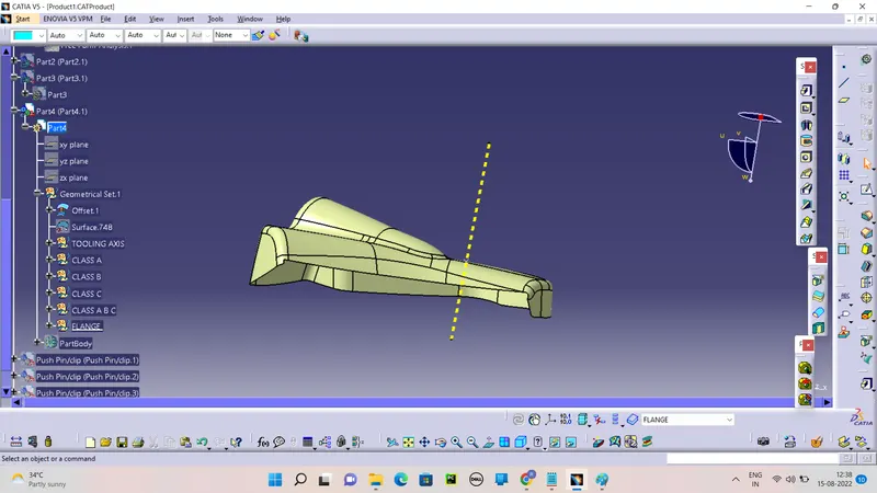
First Extract the sutable surface and create the point on the Surface. Then Create the line by the define line command by the reference of the surface and point.
CREATING THE CLASS B SURFACE:
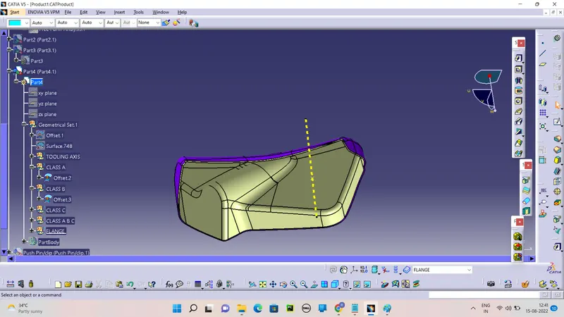
Create the Class B by the Offset of the Class A to 2.5mm guiding of Mater section. Extrapolate the Class B edges for the trim with class A.
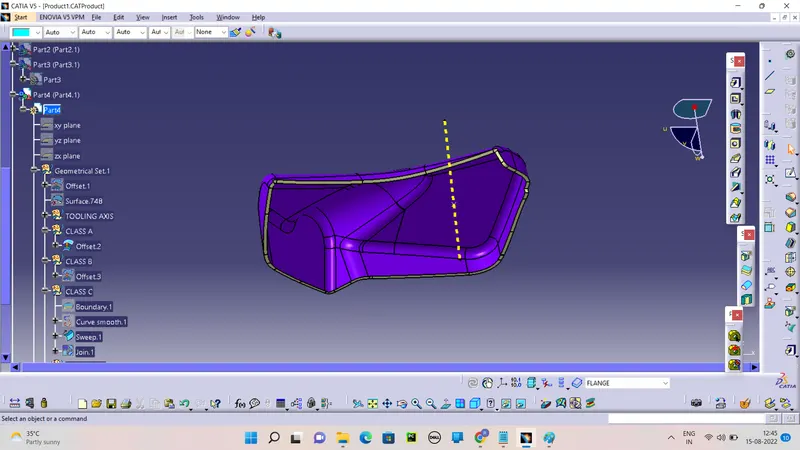
CREATE THE CLASS C:
Creating the Class C Surface by the Sweep command using the boundery Extraction and Join with Class A and Trim with Class B Surface. Make the Close view.
CREATING CLOSE VIEW:
Create the Full Close view by the join and trim command.
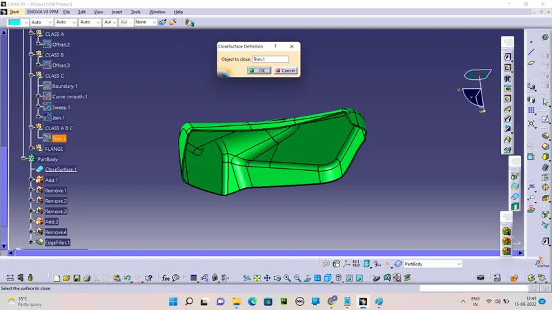
SOLID PLASTIC TRIM:
Define the Part body and create the Solid part by the Close View command.
DRAFT ANALYSIS:

FLANGES:
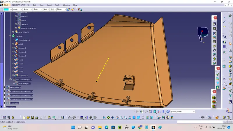
Flanges are the elements that are needed to join different components together. So here I have to make flanges on the door armrest and the map pocket. Following the master section, given as the input basically the measurements and location of the flange. I have created the flanges. First I have created the flange on the outer map pocket. For creating the flanges I have taken extraction of the curve and made a point on that curve then created one plane on that point followed by creating a sketch on that plane taking the point created as the origin.
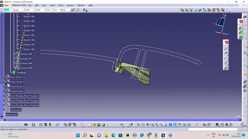
Create the solid by the Thickness command.
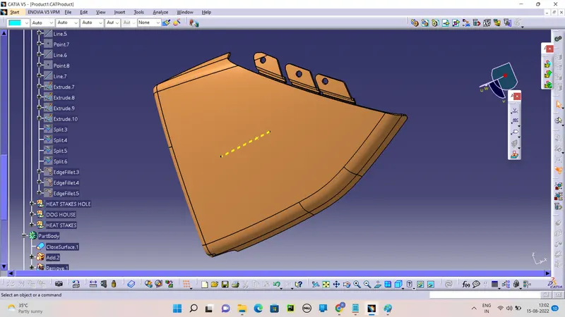
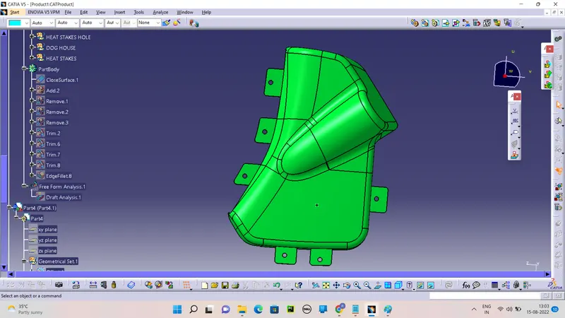
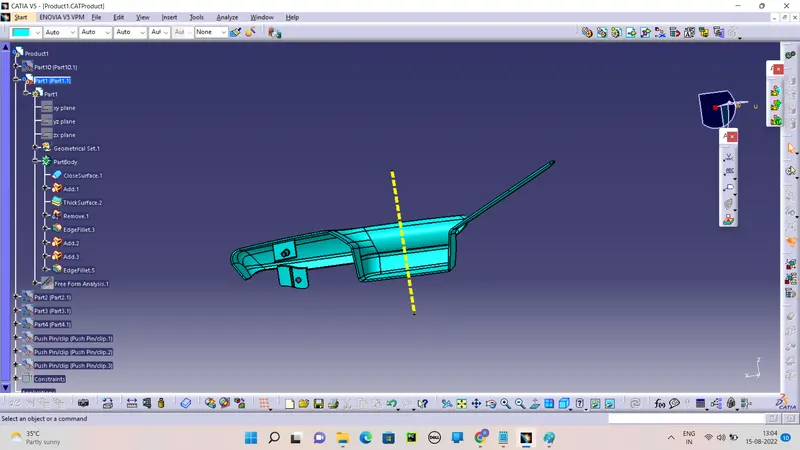
After creating the flanges I have created the dog house.
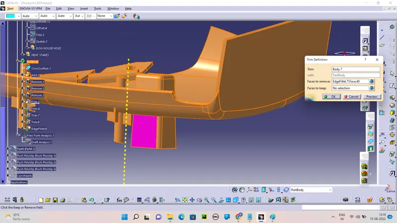
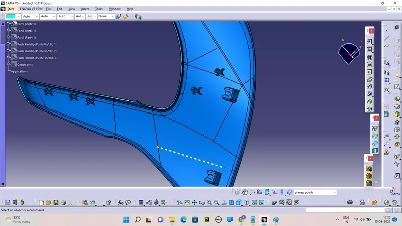
Dog House-Dog house is an engineering feature used in the plastic trim design. Doghouses are used as supporting features. Sometimes other engineering features like snaps; locators, etc. are mounded on them to increase their strength. Dog houses are subjected to draft analysis to prevent breakage of the component during ejection from the mold cavity. Dog house and other engineering components are built on B-surface.
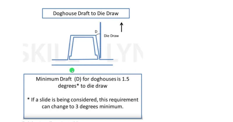
Here the dog house is required for lower substrate only. So for creating the dog house I have extracted the base surface of the lower substrate and made a point that extracted surface and sketched on it. The sketch is shown below.
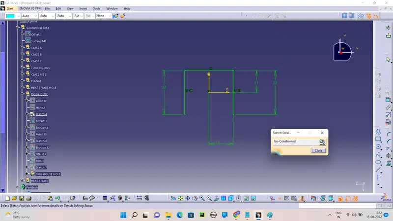
Create the Dog House by the thickness method and using the Boolean operation.
PUSH PINS:
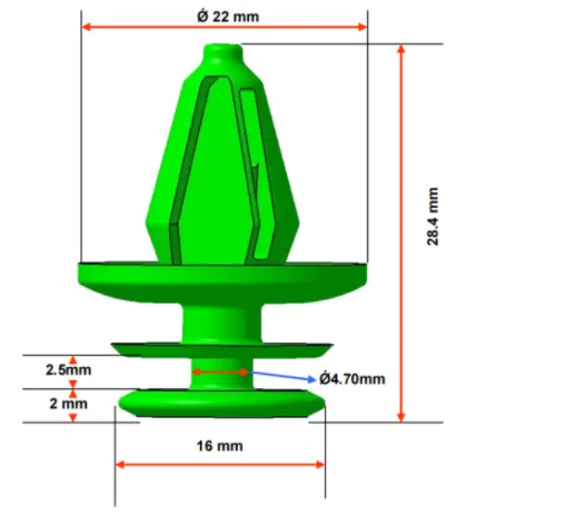
Push pins are used for joining one component to another. These are basically attached to the dog houte For creating the push pins I have taken the following reference basically the measurements
ASSEMBLY OF PUSH PINS
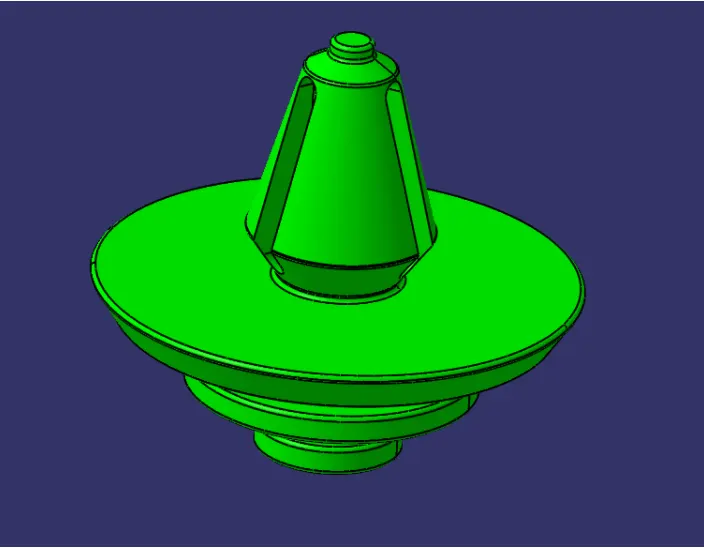
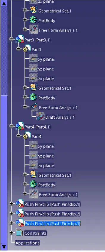
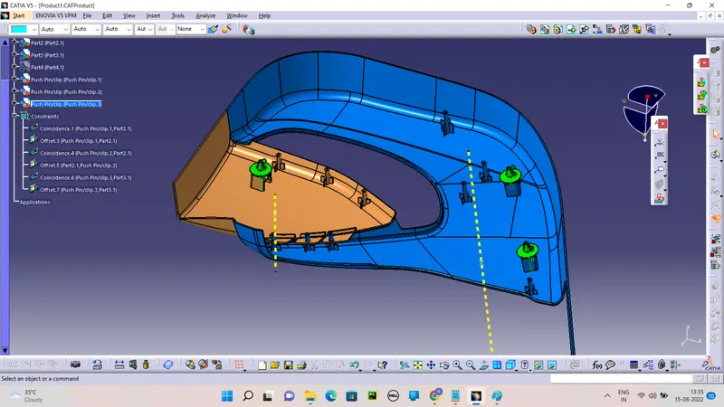
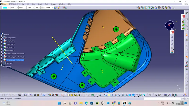
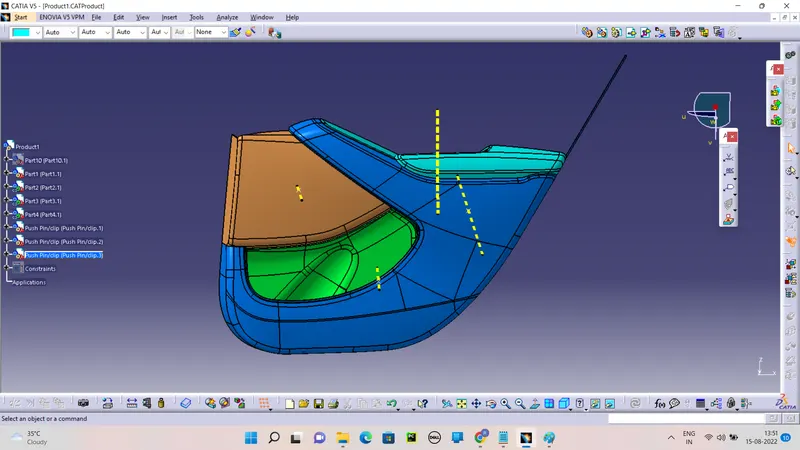
Pushpins were placed on the dog house. Total three push pins were used. Following mates are used to fixing the push pins to the dog house.
Assemble the push pin on the dog house by the constraine and offset command in the Product workbench.
HEAT STAKES AND RIBS:
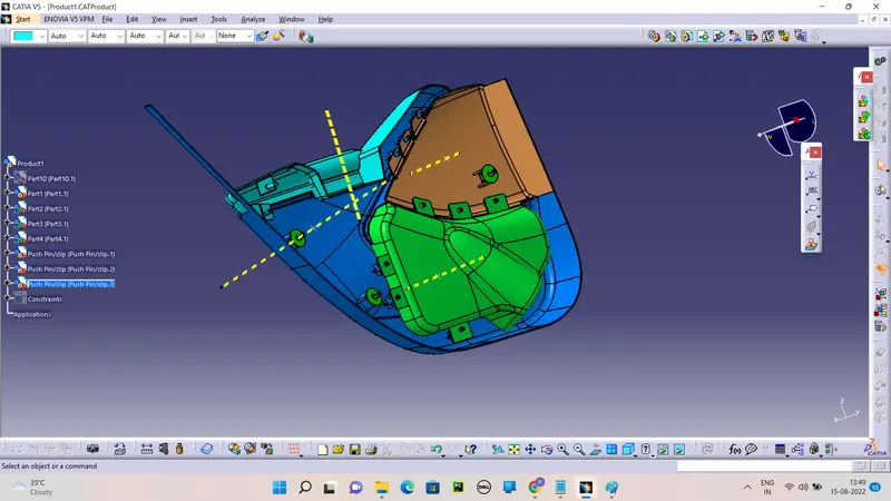
The use of heat stakes is to attach two plastic components permanently. A total of 12 heat stakes were placed at different locations on the lower substrate. One heat has been created onto the door armrest part which will be attached to the upper substrate. Following the muster section, the outer diameter of the heat stake is 7.5 mm and the inner diameter is 4.5 mm. Necessary slots are made onto other parts where heat stakes will attach together. Draft of 0.5 degrees has been given to all the heat stakes. All the heat stakes have ribs attached to them. All the ribs have 1mm thickness and 0.5 degrees of the draft. The length of the ribs is 14 x 14 mm.
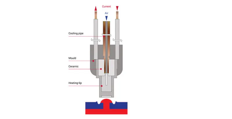
Heat staking also known as thermoplastic staking is the process of joining two dissimilar materials together. In heat staking, we use local heating and cooling to raise the temperature of plastic components and allow plastic reforming to be carried out. This reforming can be used in a wide variety of applications.
TREE STRUCTURE: