Week 11 - Final project
Hi Colleagues,
I am going to submit Final project challenge as a final part of Automotive plastic part design.
At the first I want to thank myself for helpful suggestions of Mr.Senthil,Mr.Nirmal,Mr.Shrikanth and Mrs.Rajesh.Many thanks dear colleagues for your valuable directions and remarks,you have my gratitude.
I have to add on the beginning,CLASS A SURFACES that I had got as an INPUT where not so good and I have to correct or adjust all four of them,but I presume it is done so in order to see,practice and try various aspects on designing and working on those Surfaces/Parts.
DESIGNING PARTS
So,at first I have to design parts on the basis of given INPUTS that contains CLASS A SURFACES and MASTER SECTIONS.
The first Part that I will design is named ARM_REST_TOP as it is shown bellow.
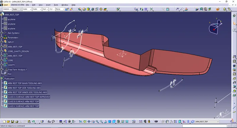
As it can be seen that is a part with a very complex surfaces.After detailed overview of all sides of the part and surfaces and edges it is immediately clear that,it will be hard to make a part and it will require three Tooling axis and complex mechanisam to pull the part out of the tool after melted material is injected and cooled.
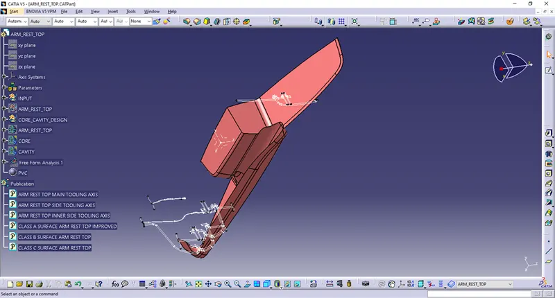
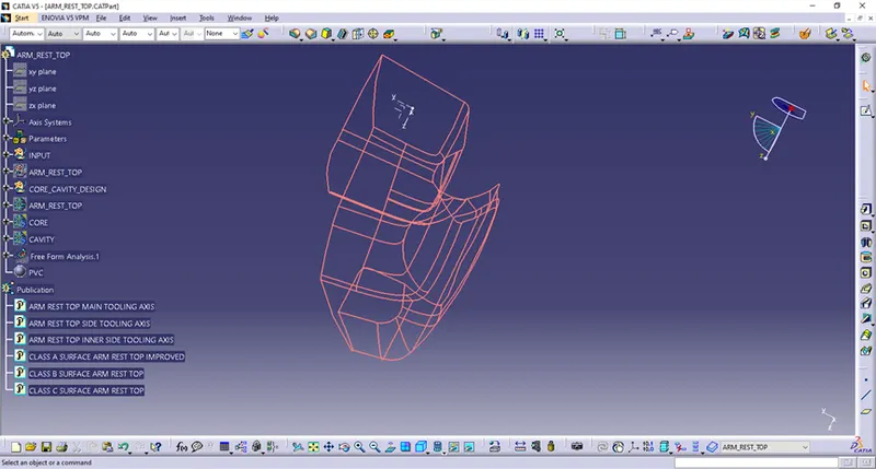
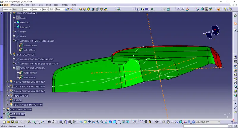
At first I have looked a part and put a main Axis as it is shown in picture,on the bottom of the part approximately in middle.
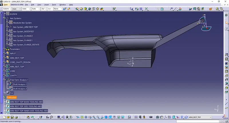
On the basis of that Axis coordinate system I have done intersecions with CLASS A SURFACE on on that basis I have done bisecting lines and constructed MAIN TOOLING AXIS and SIDE TOOLING AXIS.
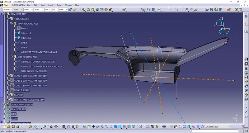
At the beginning I have tried various options in order to get the most best possible result – that is why is and blue Axis named TOOLING_AXIS_MODIFIED given,but after many tries I have concluded I will need three Axis,it is impossible with two Axis pull out Part of the mold.That is why other three Axis (that are valid for Part) are given in orange colour.The blue Axis is used to show principle of the extracting part with devided Surfaces (in one session it is said,that Part contains two combined Parts and Draft Analysis and Core/Cavity I can define and show in one direction (blue Tooling Axis).
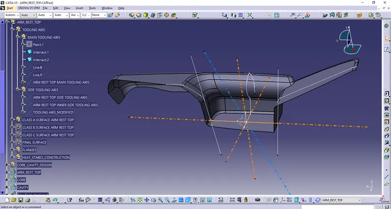
Then I have done Draft Analysis on the MAIN_TOOLING_AXIS.It shows satisfactory result.Other two directions of extraction will resolve SIDE_TOOLING_AXIS and INNER SIDE TOOLING AXIS.
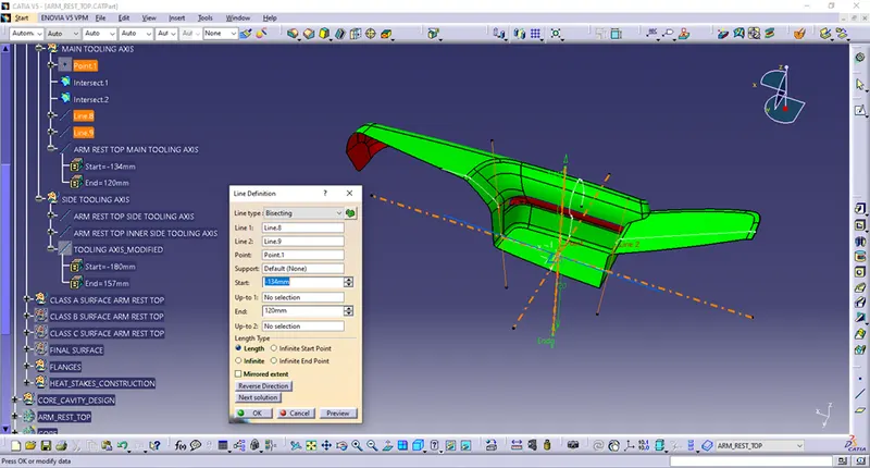
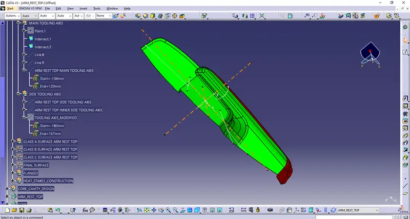
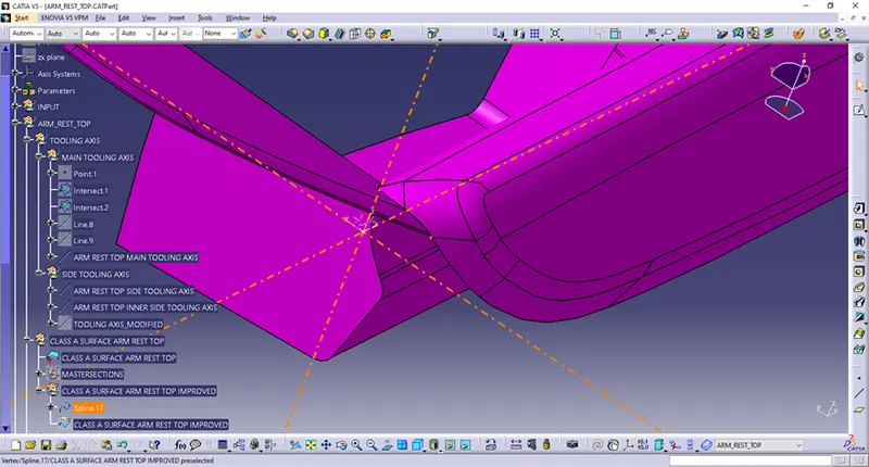
Then,I have noticed there was one place with sharp edges,on it was impossible to make junction and a sweep. I have to correct CLASS A SURFACE in order to be able to close Surfaces.
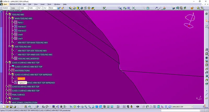
I have drawn a Spline and Splited - corrected CLASS A SURFACE from INPUT and got CLASS A SURFACE that I had renamed as a CLASS_A_SURFACE_ARM_REST_TOP_IMPROVED.
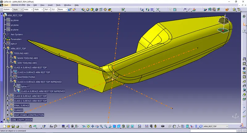
After Tooling Axis are done and Draft Analisys was satisfying I have started to design CLASS B SURFACE.
Now I have dealt with a CLASS B SURFACES.
I have inserted Geometrical Set and rename it as CLASS_B_SURFACE_ARM_REST_TOP.In that area I have devided Part Surfaces in two areas – Geometrical Sets and named it as OUTTER_WALLS and OUTTER_SIDE_WALLS.
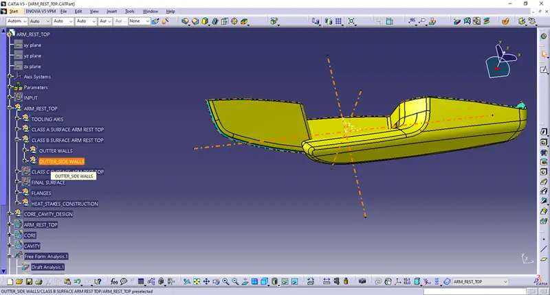
As it can be seen I have done many times extract,offset,surface untrim,boundary and split procedure in order to get a proper offseted surfaces.
Sometimes I had to make a splines and fills or multisection solids to get a proper shape.
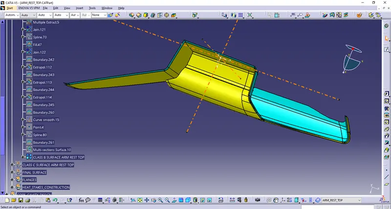
Especially troublesome area was here.That are should be corrected in a CLASS A SURFACE area.I have done CLASS B SURFACE here folowing all rules,but in order to get a proper shape that area of CLASS A SURFACE should be corrected.
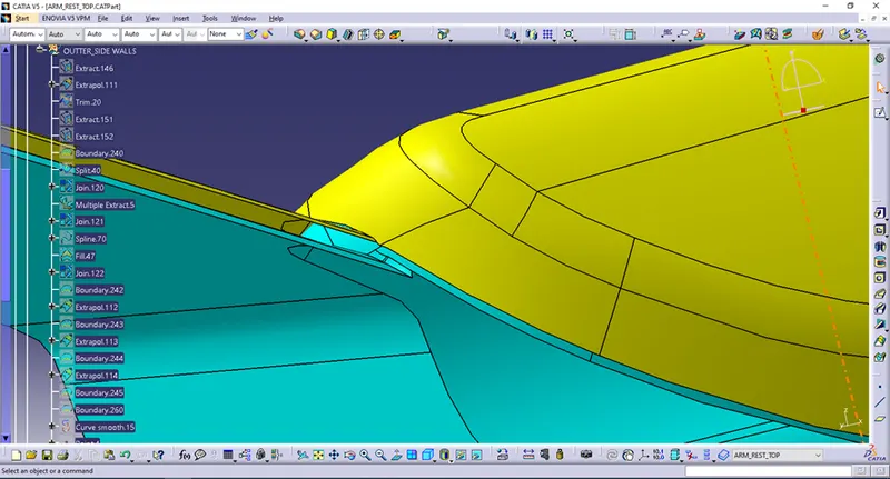
Finally I had connected and joined all offseted surfaces.As it can be seen,it is joined with a 0.007mm,it should be discussed if that satisfies (regulation says it should be 0.001-0.003mm).
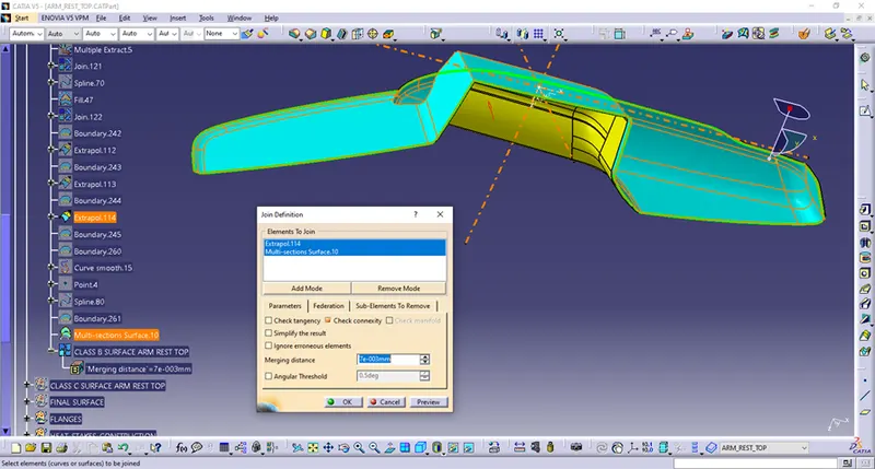
Joined surfaces I named as CLASS_B_SURFACE_ARM_REST_TOP.
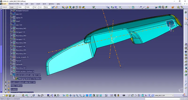
After CLASS B SURFACE I was constructed CLASS C SURFACE.At first I have inserted new Gemetrical Set and renamed it as CLASS_C_SURFACE_ARM_REST_TOP.It could be seen that this Surface have many problematic areas to conduct Sweep on entire boundary.Especialy problematic areas were shown on images bellow.
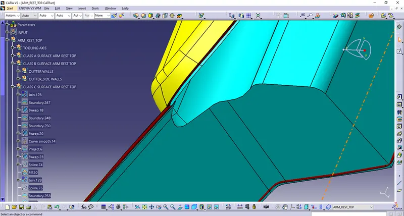
That is problematic area and shoud be take in consideration by making changes of CLASS A SURFACE rearrangement.
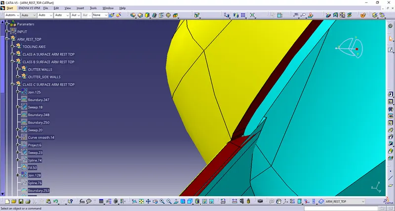
After I sweeped,trimed,filleted and joined all boundary surfaces I joined it finally in a one Surface and named as CLASS_C_SURFACE_ARM_REST_TOP.
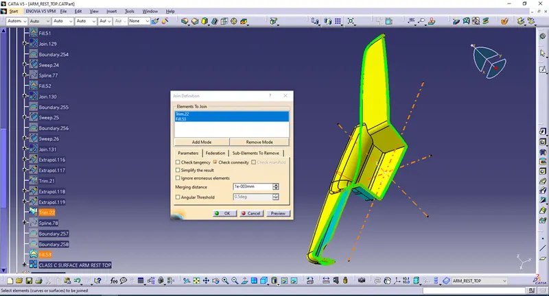
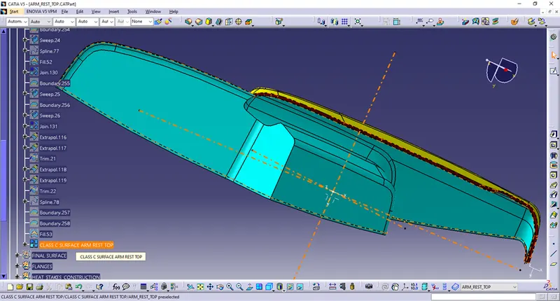
Then I have joined CLASS_A_SURFACE_ARM_REST_TOP_IMPROVED and CLASS_C_SURFACE_ARM_REST_TOP.
At the end I trimmed that Join with a CLASS_B_SURFACE_ARM_REST_TOP.
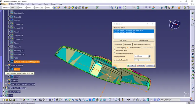
In order to be able to close those Surfaces I have increased Join tolerance from 0.001mm to 0.003mm.
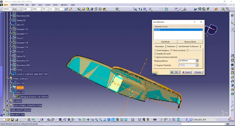
Finally I have closed Surfaces and made new Solid Part that I have named ARM_REST_TOP.
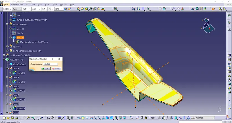
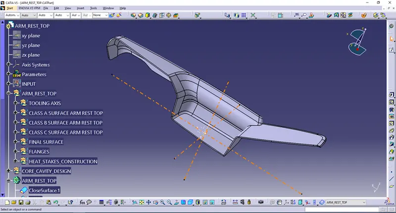
Now I have done Draft Analysis on the Part also.
As previously I have done it with MAIN TOOLING AXIS (as discussed on session,as practice,although I have defined three Tooling Axis for Part extraction).
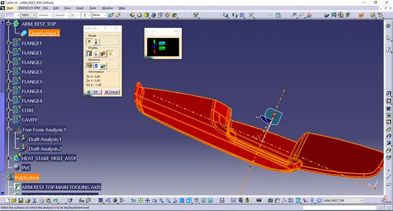
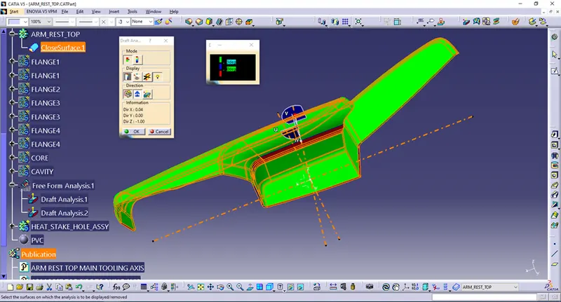
As it can be seen I have done Draft Analysis on a Part without Flanges and Heat Stakes that I added after one discussion during the work on Project.
In order to join Parts together in a Door Assembly I have added Flanges and Heat Stakes using Assembly,Union Trim and Remove (for Holes in Heat Stakes).As it is shown Flanges,Heat Stakes and Holes are aligned in one direction,following SIDE TOOLING AXIS and with respect to INPUT MASTERSECTION.
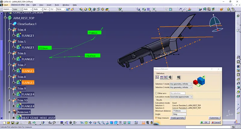
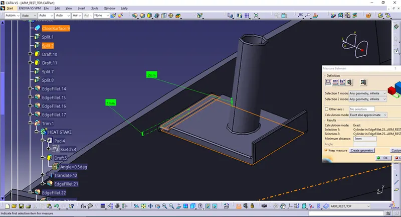
Heat Stakes are approximately 20mm high,1mm thick and under 0.5deg draft. They are 0.3mm filleted.
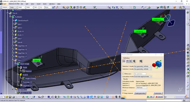
Flanges are 2mm thick,done also under draft 0.5deg and filleted 0.3mm.At the bottom they are having thicknes of 1mm in order to avoid too thick joints that will cause failures and mistakes on surfaces.
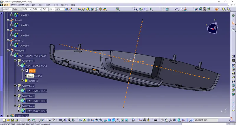
After I have designed Part I had to construct Mold for it – Core and Cavity.That is why I have inserted two new Geometrical Sets and named it as a CORE and CAVITY under CORE_CAVITY_DESIGN Geometrical Set.
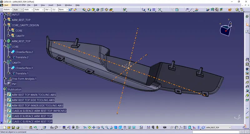
As I have discussed various isuess of this part and problems on session,CLASS_A_SURFACE, Tooling and extraction of the Part basis it was decided that I should give Tool for a piece of Part as it is showed in images for CORE and CAVITY (and it is said,the part consists of two parts anyway).So,after I have done various operations regarding Generetive Shape Design I have designed Parting Surface and a Parting Line and CORE and CAVITY Mold Parts also.
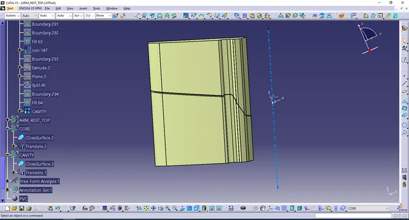
As it can be seen on image bellow,I have done closed Surface Geometry in CORE_CAVITY_DESIGN in inserted New Body Parts.Those Surfaces were closed to make Solid Parts – CORE and CAVITY.
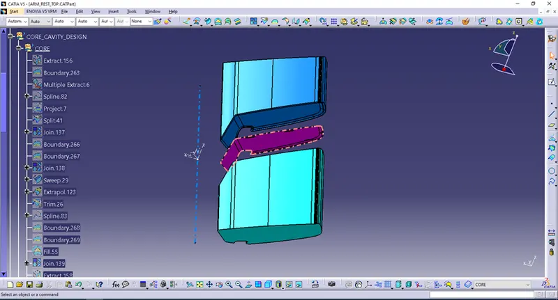
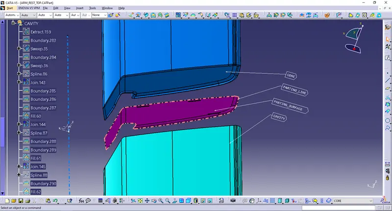
New Body Parts I have named CORE and CAVITY and there I have transformed Surfaces in Solid Parts.After converted in Solids I have translated it in Tooling Axis direction for 50mm.
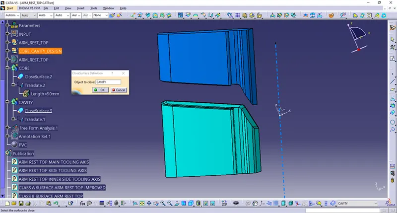
At the end I had applied material (PVC) on Part and published all caracteristic features.
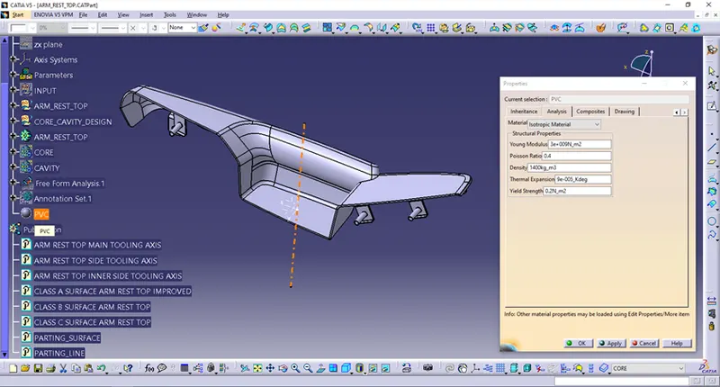
After I have done ARM_REST_TOP next Part to deal with were DOOR_PANEL.
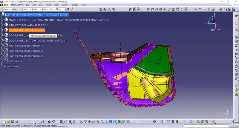
I have opened Part and as on ARM_REST_TOP (just to mention,3 Tooling Axis needed) I had noticed I will need two Tooling Axis here,one is not enough.
There is one extensions of the Part and when Mold opens in Main Tooling Axis direction,it will be impossible because of that extension.That is why I need two Tooling Axis.
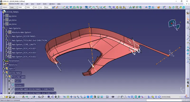
So,In the New DOOR_PANEL part I have inserted INPUT from the MASTER_SECTION_DEVELOPMENT_INPUT.In a DOOR PANEL Geometrical Set I have inserted Geometrical Sets TOOLING_AXIS,CLASS_A_SURFACE_DOOR_PANEL, CLASS_B_SURFACE_DOOR_PANEL,CLASS_C_SURFACE_DOOR_PANEL and a FINAL_SURFACE as previously.
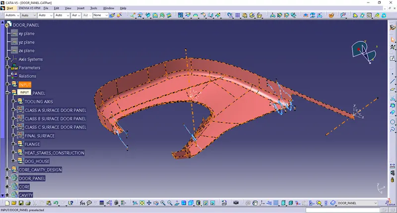
Under the Geometrical Set CLASS_A_SURFACE_DOOR_PANEL I pasted CLASS_A_SURFACE from INPUT.Regarding that Surface and considering taken Tooling Axis I should do Draft Analysis in order to check manufacturability of the Part.
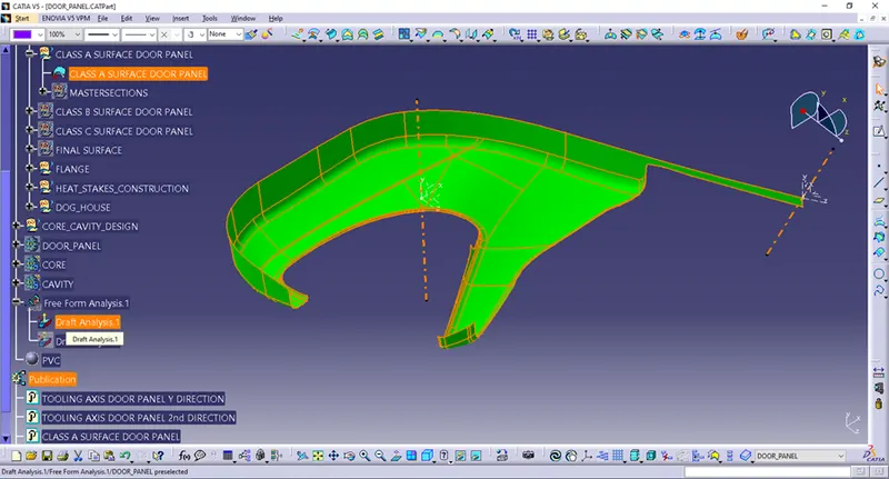
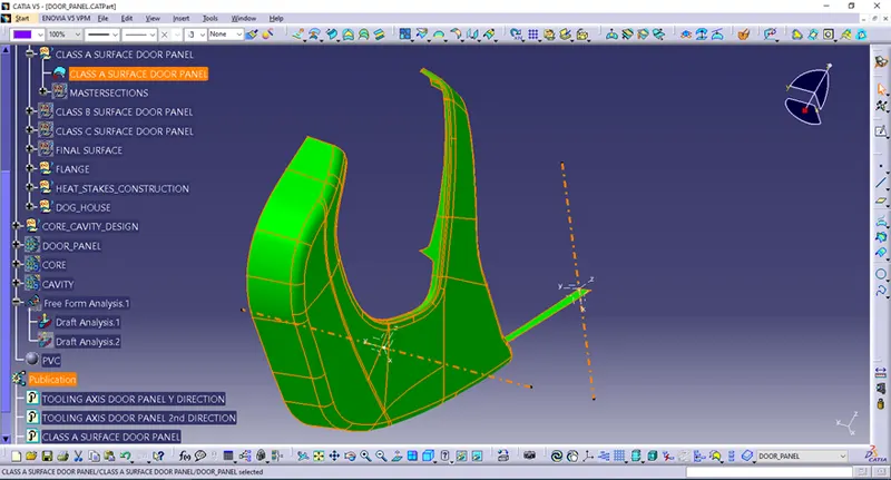
It can be seen that the Part could be manufactured regarding taken Tooling Axis for a given CLASS_A_SURFACE.
After I have done Tooling Axis (Main and 2nd direction) I have started to design CLASS_B_SURFACE_DOOR_PANEL on the basis of CLASS_A_SURFACE_DOOR_PANEL.
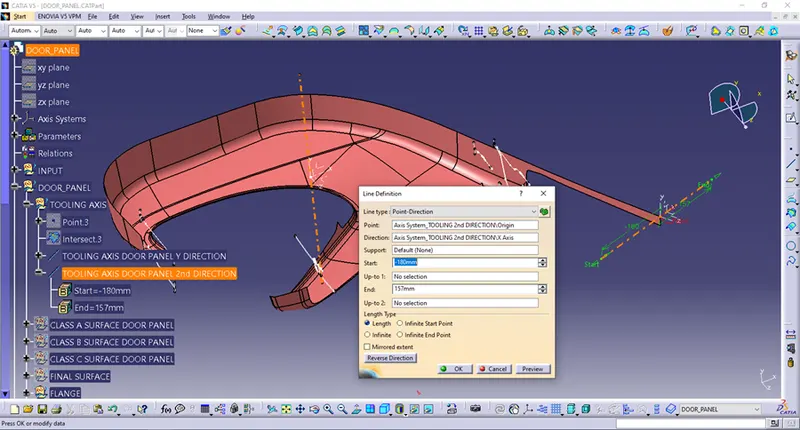
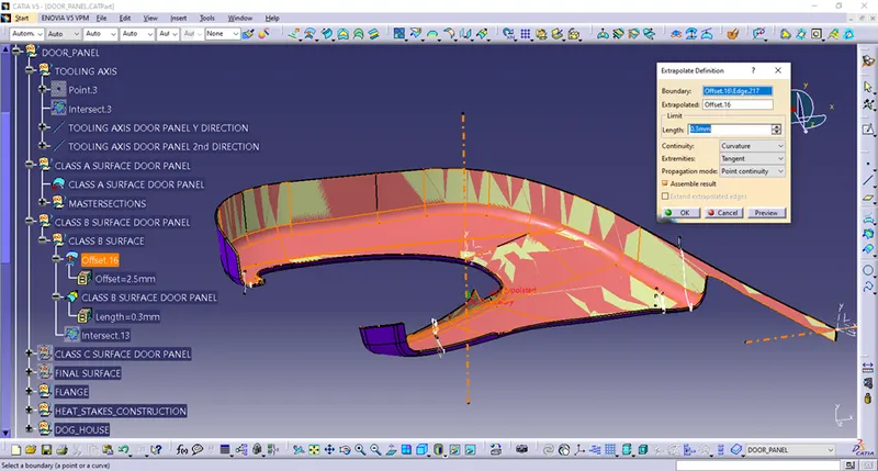
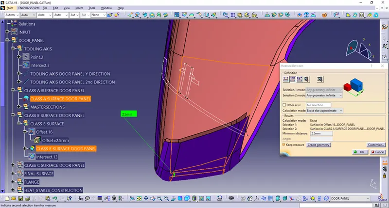
I have inserted CLASS_B_SURFACE Geometrical Set and under it I offseted (for a 2.5mm) and extrapolated CLASS_B_SURFACE.
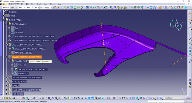
Then,it was time to make a CLASS_C_SURFACE.
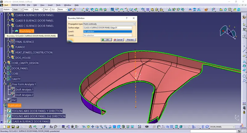
In inserted CLASS_C_SURFACE_DOOR_PANEL I made first feature – Boundary on CLASS_A_SURFACE .
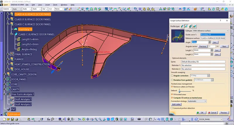
After that I made Sweep on that Boundary and CLASS_A_SURFACE.Surface I have got,is a CLASS_C_SURFACE_DOOR_PANEL and so I have renamed it.
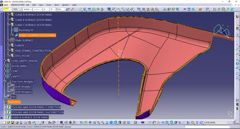
In already inserted Geometrical Set FINAL_SURFACE I have first joined CLASS_A_SURFACE_DOOR_PANEL and CLASS_C_SURFACE_DOOR_PANEL.
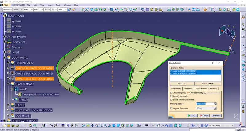
I have then trimmed that Join with CLASS_B_SURFACE_DOOR_PANEL and got closed Surface.
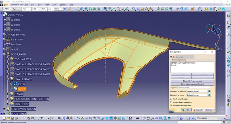
Afterwards I have changed enviroment from Generative Shape to Part Design and inserted new Body Part that I have renamed as DOOR_PANEL.
There I have closed Surfaces and made Solid part.
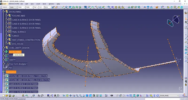
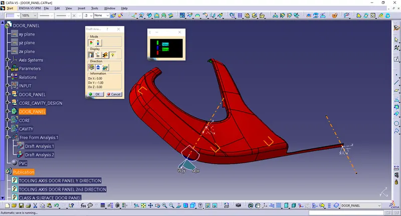
Then I had to do Draft Analysis for the Part.
It can be seen Tooling Axis and Part are well defined.
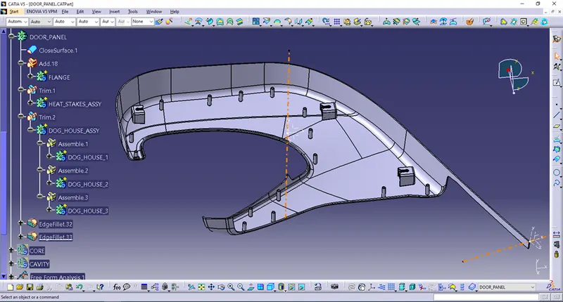
I have showed that,how I made a Part,but I did not say that I have also done Assembly Features as well.Assembly features (HEAT STAKES and DOG HOUSES) are under 0.5deg angle,that is why are they in blue colour doing Draft Analysis.
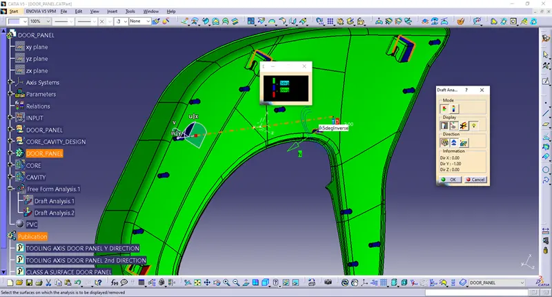
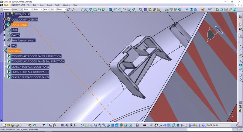
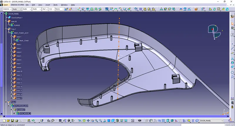
So,I will now say a few words about Assembly Features.On previous part (ARM_REST_TOP) I had a Flanges and a Heat Stakes on Flanges also,as it is defined in Mastersection.Flanges are having holes also,to be able to connect them with Heat Stake from another Part.Heat Stakes Holes on Flanges are done to connect two Parts regarding geometry of the Parts.Here,on the DOOR_PANEL I have made many Heat Stakes because as a biggest lower substrate I have defined that Part as a base Part in Assembly strategy attachment for Door Assembly.Geometry of the Heat Stakes are given on images bellow (height ca.20mm,thickness 1mm under 0.5deg draft angle).On this part I have given DOG HOUSES also in order to connect that entire Assembly with a BIW (Body in White – Car Body) with the aid of Push/Pins.Dog Houses are also done with a height of ca.20mm,under 0.5deg draft and with the thickness at the bottom ca 0.8mm.Heat Stakes and Dog Houses are done with that thickness at the bottom in order to avoid sink marks and failures on the Part surfaces (especially visible sides).Attachment Features design and strategy is defined so,that with Heat Stakes using heated Tool Heat Stakes will be heated and pushed on the other Part Flanges and then melted parts are pressurised and connected one to another.
As it can be seen Heat Stakes and Dog Houses are aligned with Main Tooling Axis direction.
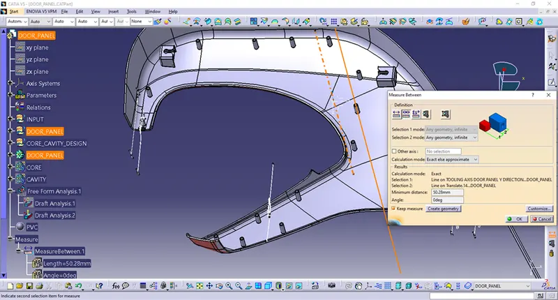
Heat Stakes and Dog Houses are at first designed in Geometrical Sets called that way and afterwards in Part design module closed surfaces are converted in solid Parts.
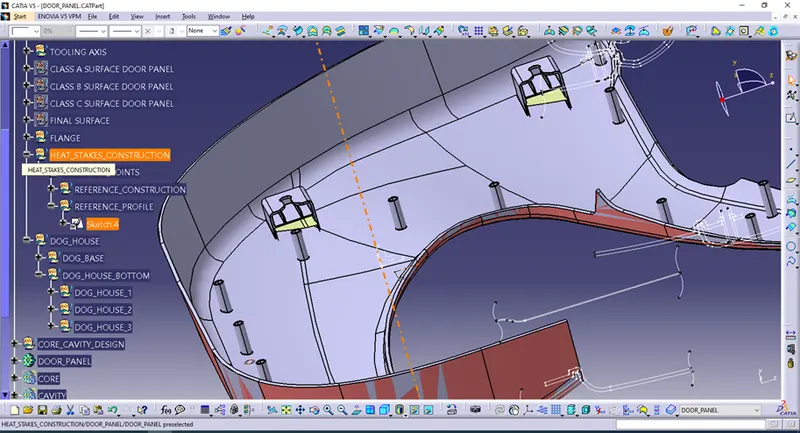
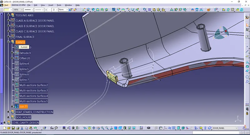
In addition I have designed and one Flange according to Mastersection.
Dog Houses are designed with respect to the Geometry of Push/Pins and Surface of the Part at bottom,following Surface and with thicknes of ca.1mm at the bottom and fillet of 0.3mm.
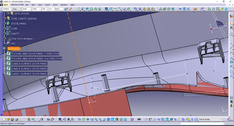
After I had converted closed surfaces to the new Body Parts,that I have named as FLANGES,HEAT STAKE and DOG HOUSE I have first made Assembly of HEAT_STAKE as a HEAT_STAKES_ASSY and of DOG_HOUSE as DOG_HOUSES_ASSY.
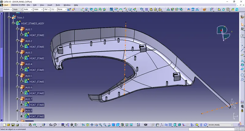
Then I had Added and Union Trimmed all those Attachment Features and filleted them with 0.3mm.
After that I had designed Mold Parts – CORE and CAVITY.I had inserted Geometrical Set CORE_CAVITY_DESIGN and under it CORE and CAVITY Geometrical Sets where I had constructed Core and Cavity Surfaces on the basis of DOOR_PANEL Part and TOOLING AXIS (extraction direction).
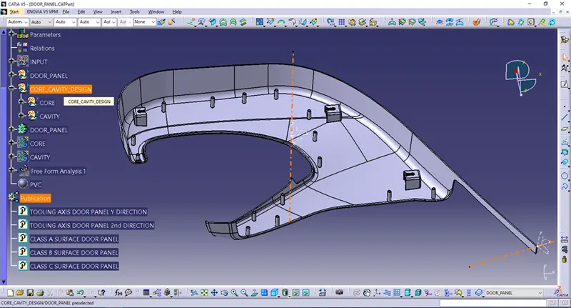
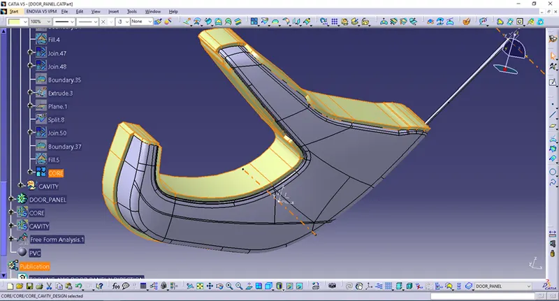
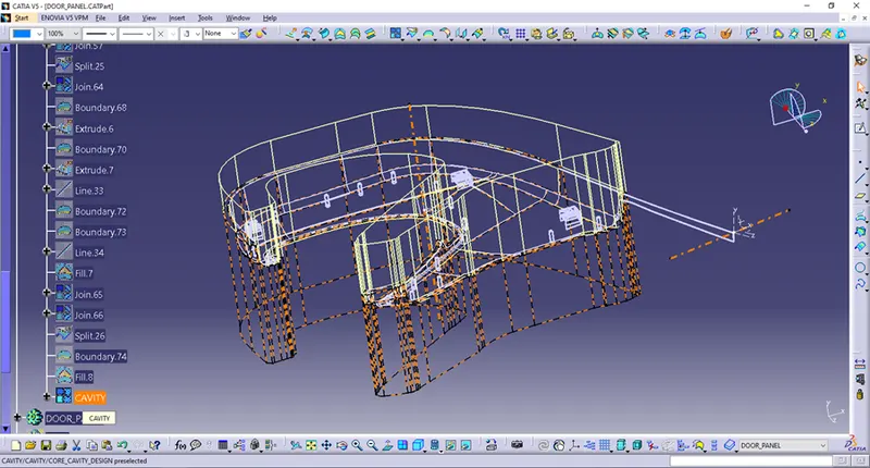
During one discussion about this Part and Tooling it is agreed that I should take in consideration one Axis – Main Tooling Axis and neglect the other direction of Tooling Axis.I had done CORE and CAVITY with one Tooling Axis.
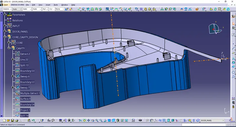
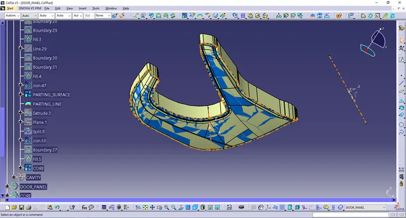
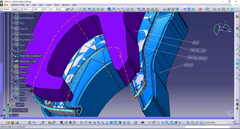
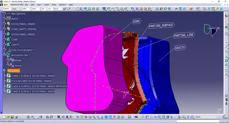
Basicaly on the PARTING_SURFACE,that I have constructed after extract and extrapolation of the Part Surfaces I have boundary on PARTING_SURFACE and that is my PARTING_LINE (closing line of the Mold,line when CORE meets CAVITY).Those features are representing closing surface of Mold and should be designed and machined with greatest attention.
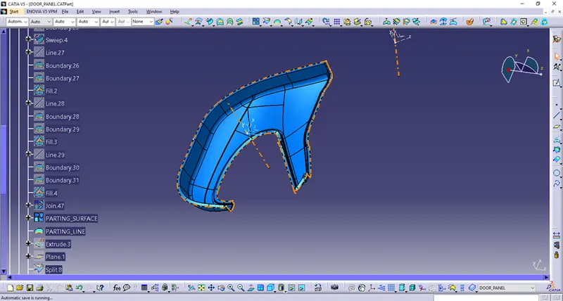
After I had done PARTING_LINE,I have extracted that line in Tooling direction to get my CORE and CAVITY Surfaces.
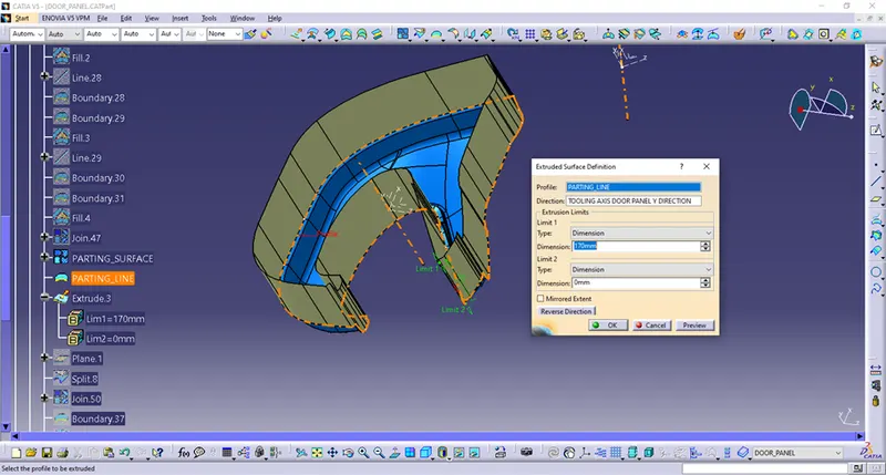
After I had ectracted PARTING_LINE I have enclosed all Surfaces.
The same procedure I have done to CAVITY.
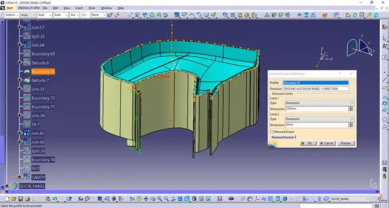
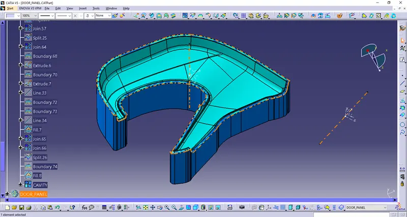
On the basis of that two Geometrical Sets (CORE and CAVITY),and afther I made Closed Surfaces on the basis of DOOR_PANEL Part and Tooling Axis I made Solid Parts CORE and CAVITY of the Mold.
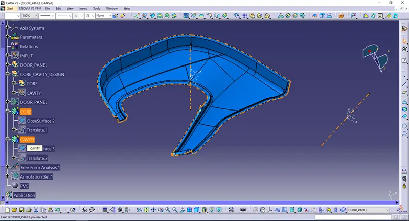
In the image bellow I have showed final form of CORE,CAVITY,PARTING_SURFACE, PARTING_LINE and a Part DOOR_PANEL (grey colour).
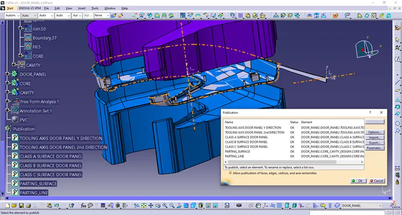
At the end of designing the Part DOOR_PANEL and Mold Parts CORE and CAVITY I have Published all characteristic Features.
Now,the next Part and its components that I should design was the Part that I named as DOOR_PANEL_INNER.
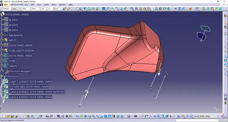
After I looked at a Surface a little bit,I have decided where I am going to put Axis system of the Part and I have seen some failures in Surface that I should correct.
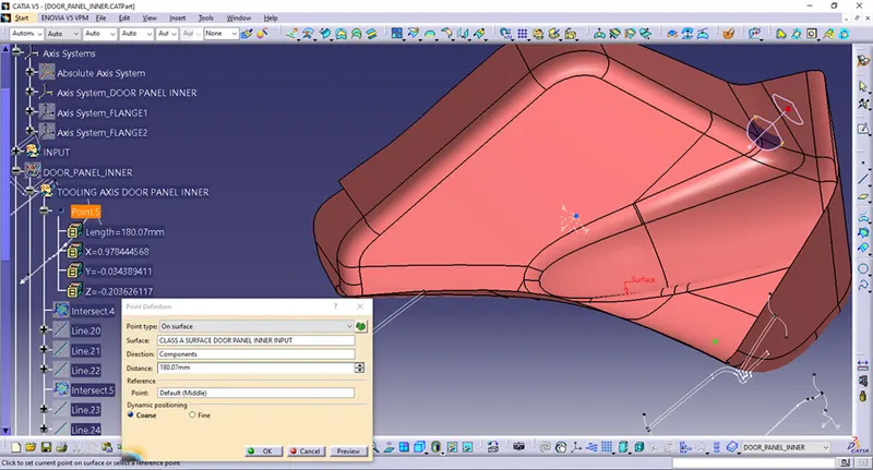
After I have positioned Axis System and copied INPUT with Surfaces and Mastersections from MASTERSECTION Part in a DOOR_PANEL_INNER Part I have also inserted New Geometrical Set DOOR_PANEL_INNER and under it Geometrical Sets TOOLING_AXIS_DOOR_PANEL_INNER, CLASS_A_SURFACE_DOOR_PANEL_INNER,CLASS_B_SURFACE_DOOR_PANEL_INNER, CLASS_C_SURFACE_DOOR_PANEL_INNER and FINAL_SURFACE.
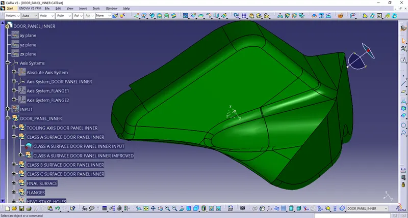
In a CLASS_A_SURFACE_DOOR_PANEL_INNER Geometrical Set I have pasted CLASS_A_SURFACE from INPUT.As I already said,that Surface should be corrected,that is why I have inserted new Geometrical Set-CLASS_A_SURFACE_DOOR_PANEL_INNER_IMPROVED.
There I had made some corrections on a CLASS_A_SURFACE to be able to form closed surfaces.
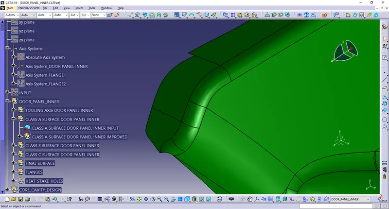
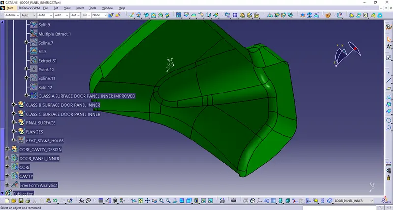
Corrections on Surfaces I made,I have saved as a CLASS_A_SURFACE_DOOR_PANEL_INNER_IMPROVED.
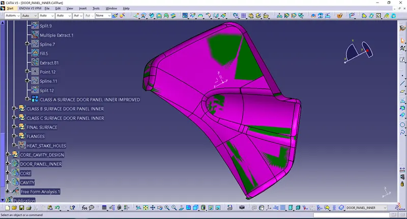
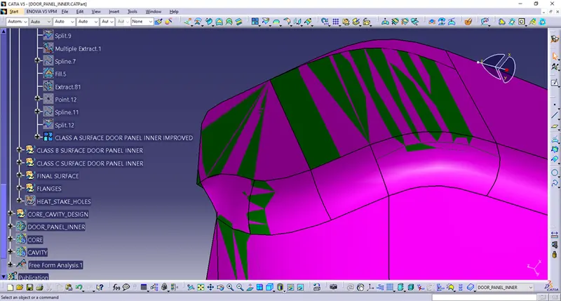
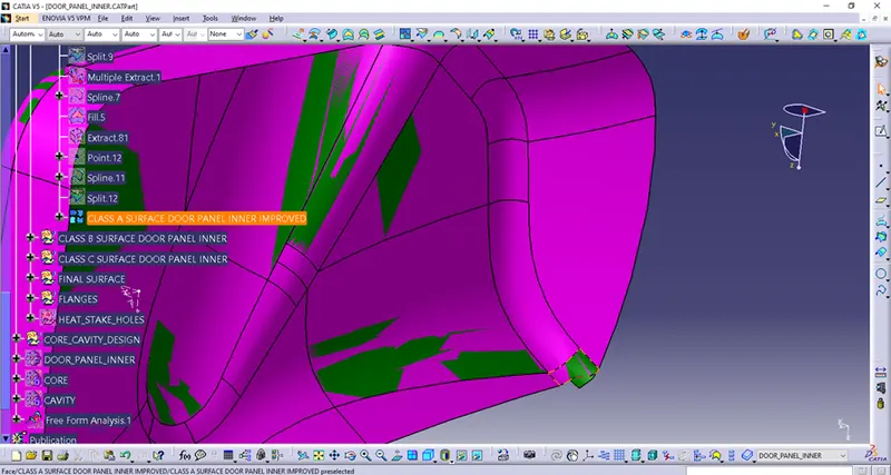
So,it was time to dealt with Tooling Axis on that improved Surfaces.After many tries (the walls are under ca.90deg to the bottom) to have the best possible solution I have done Tooling Axis as shown on image.
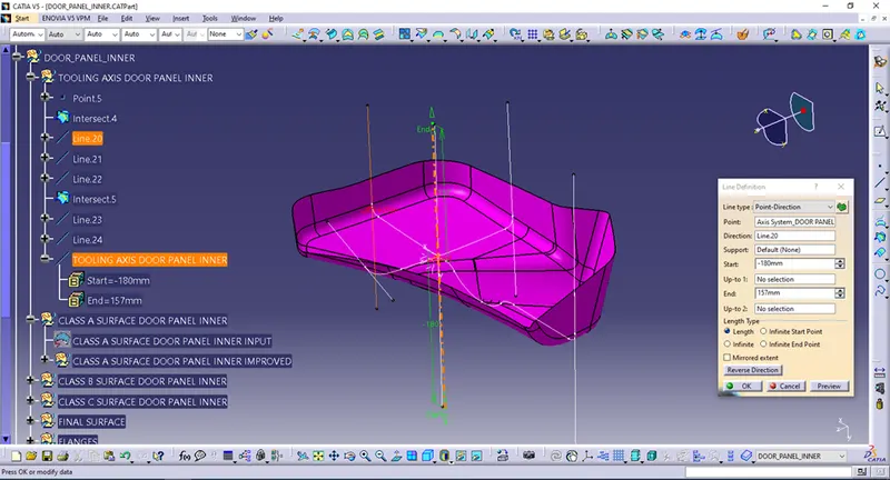
After I have done CLASS_A_SURFACE and a TOOLING_AXIS it was time to do Draft Analysis to check if all is good defined and if the Part could be manufactured regarding given parameters.
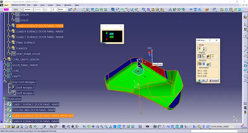
As I have already said,walls of the Part are under cca. 90deg to bottom inclined,that should be in CLASS_A_SURFACE corrected.
Then I have dealt with a CLASS_B_SURFACE_DOOR_PANEL_INNER.Under Geometrical Set with that name I have inserted new Geometrical Set – CLASS_B_SURFACE.I have first offseted CLASS_A_SURFACE for a 2.5mm and it can be seen that,offseted Surface have failures that should be repared.
That is why I have done some splines and boundaries and with respect to them and belonging Surfaces I have connected those Surfaces.
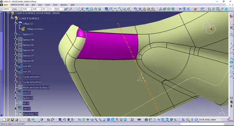
Afterwards I have extrapolated that joined Surface on boundary.
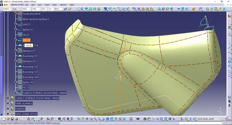
That extrapolated Surface is my CLASS_B_SURFACE_DOOR_PANEL_INNER.
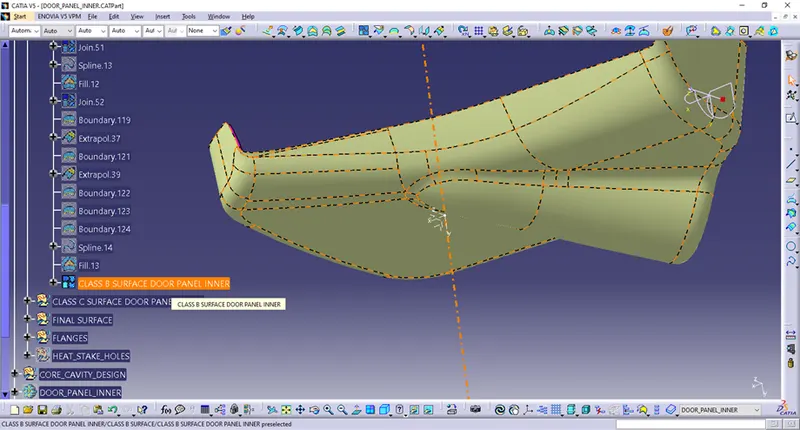
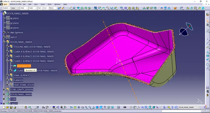
After CLASS_A_SURFACE and CLASS_B_SURFACE I have designed CLASS_C_SURFACE_DOOR_PANEL_INNER.
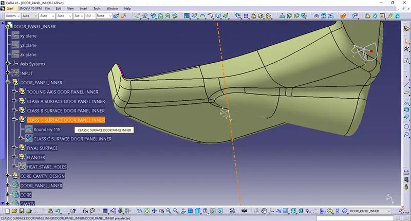
On the boundary of CLASS_A_SURFACE I have done Sweep as shown.
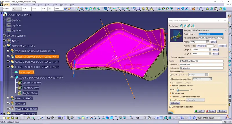
That is mine CLASS_C_SURFACE_DOOR_PANEL_INNER.
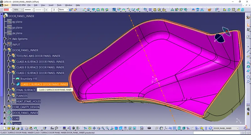
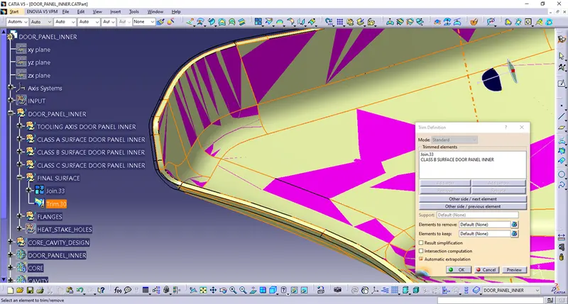
Now,in FINAL_SURFACE Geometrical Set I have first joined CLASS_A_SURFACE_DOOR_PANEL_INNER_IMPROVED and CLASS_C_SURFACE_DOOR_PANEL_INNER.
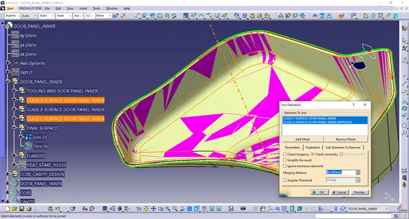
At the end I have trimmed that Join with CLASS_B_SURFACE_DOOR_PANEL_INNER and got Final closed Surface that I can convert to solid.
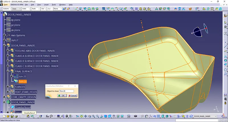
I have inserted new Body Part named as DOOR_PANEL_INNER and there I have converted Surfaces to Solid.
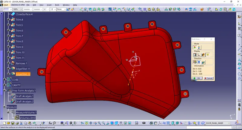
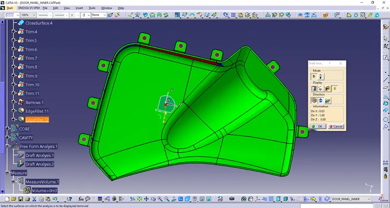
It is time to do Draft Analysis one more time, now on Solid Part regarding Tooling Axis.As I have previously said,there is a problem with almost vertical walls,that should be corrected.
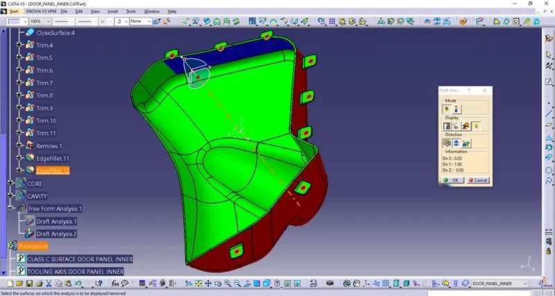
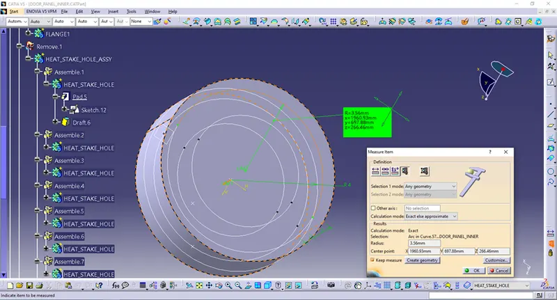
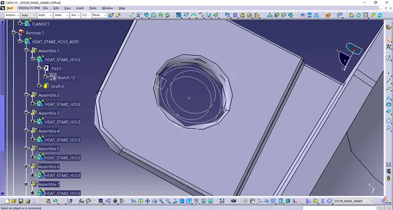
As previously mentioned,after I have done my Solid parts I was directed to do and Attachment Features using previous knowledge of Boolean Operations and so I have done it.Here can be seen,the Attachment features are also done with drafts (holes with Heat Stakes 0.5deg,that why there is blue colour).
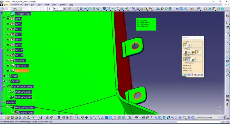
It can be seen I have designed Flanges (2mm thick and at the bottom,where the walls of the Part are 1mm thickness and with 0.5deg Draft) and Heat Stakes Holes that I have Removed from Flanges (Boolean operations).Flanges were with Union Trim connected to the Part and all is with 0.3mm filleted.
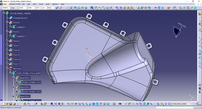
HEAT STAKES HOLES I have so constructed,that way they are following positions of the HEAT STAKES and inclination – they are done with inclination regarding HEAT STAKES and TOOLING AXIS.
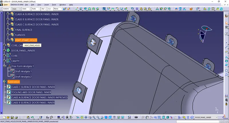
Now,it was time to make Mold Parts – CORE and CAVITY.That is why under CORE_CAVITY_DESIGN Geometrical Set I had inserted CORE and CAVITY Geometrical Sets.
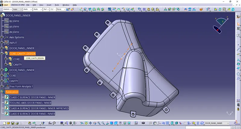
At first under CORE Geometrical Set I have extracted,extruded,sweeped and filled Surfaces of the Part and got PARTING_LINE and PARTING_SURFACE.
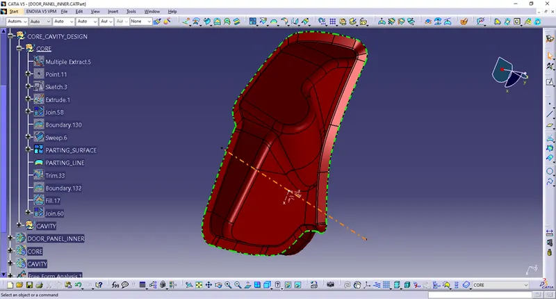
On the basis of PARTING_LINE I have extruded Surfaces in direction of Tooling Axis and got Surfaces that I can close and convert to Solid.
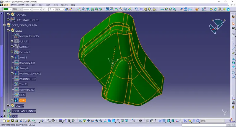
On the same way I have constructed CAVITY.I have extracted,extrapolated and trimmed Parting Surface with extrude and got a Joined Surface that I can convert to Solid.
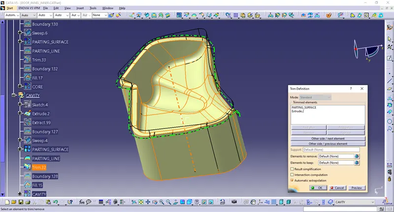
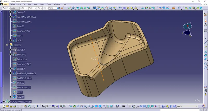
After I had done CORE and CAVITY under Geometrical Sets I converted them to Solids under already inserted new BodyParts named as CORE and CAVITY.
I have converted CORE and CAVITY to Solids and translated them in Tooling Direction for a 100mm.
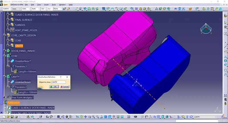
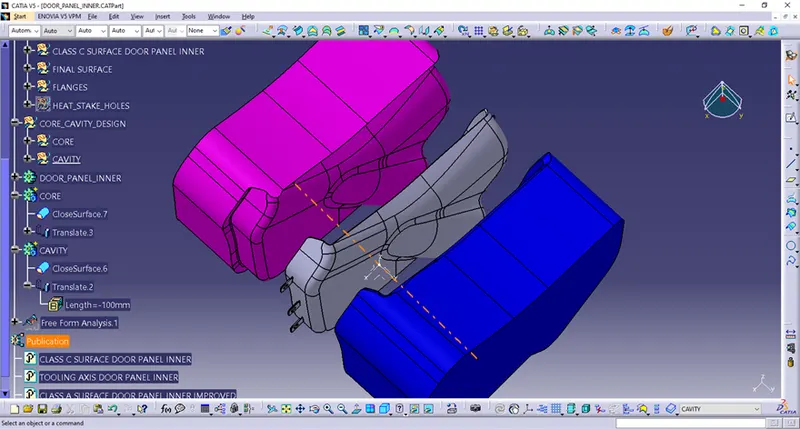
As previously said,I have done Parts without Attachment Features at first and on that base I was directed to make a Mold Parts.
All Parts are shown on image bellow – DOOR_PANEL_INNER with Attachment Features,PARTING_SURFACE, PARTING_LINE.
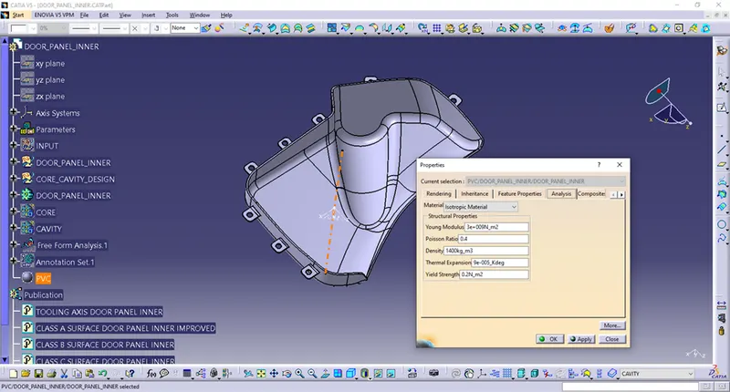
On the Part material is applied.
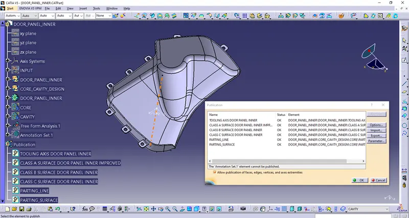
Finally I have Published all characteristic Features.
It is one more Part left – I have taken a CLASS_A_SURFACE from INPUT in MASTERSECTION and pasted it in a new made Part that I named as DOOR_PANEL_BOTTOM.

Then I have inspected where is the best to position Axis system and I have also inserted new Geometrical Sets called DOOR_PANEL_BOTTOM and under it Geometrical Sets TOOLING_AXIS, CLASS_A_SURFACE_DOOR_PANEL_BOTTOM,CLASS_B_SURFACE_DOOR_PANEL_BOTTOM,CLASS_C_SURFACE_DOOR_PANEL_BOTTOM,FINAL_SURFACES (at later stage I have inserted FLANGES and HEAT_STAKES_HOLES also).
I have positioned Axis system DOOR_PANEL_BOTTOM approximately in the middle of the Surface.
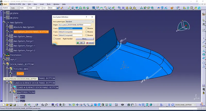
Under Geometrical Set CLASS_A_SURFACE_DOOR_PANEL_BOTTOM I have pasted CLASS_A_SURFACE and MASTERSECTIONS from INPUT.
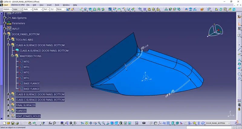
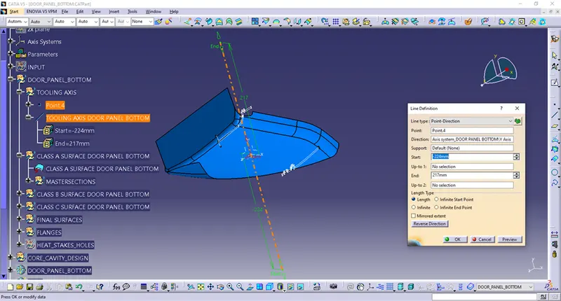
Then I have constructed TOOLING AXIS under that Geometrical Set as shown.
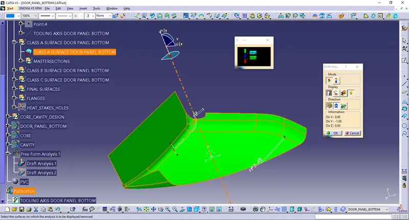
I had done Draft Analysis on that CLASS_A_SURFACE regarding TOOLING_AXIS_DOOR_PANEL_BOTTOM.It can be seen the Part and Tooling Axis are satisfying Draft Analysis.
Afterwards it was time to design CLASS_B_SURFACE_DOOR_PANEL_BOTTOM.I had offseted CLASS_A_SURFACE and then I have seen some failures on offseted Surface that I should repair.
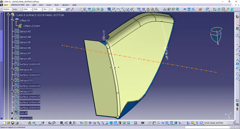
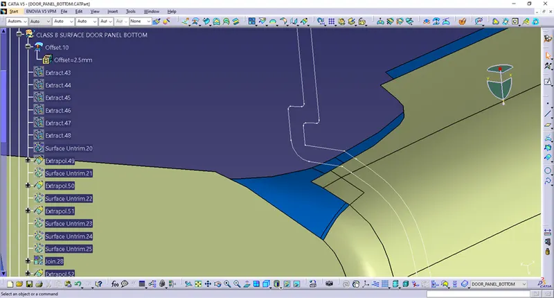
After I have repaired those Surface,there were also problems regarding offset and then extrapolate those Surfaces.That is why I have taken a different approach.
I have Extracted,Surface Untrimmed and Extrapolated all those Offseted Surfaces.
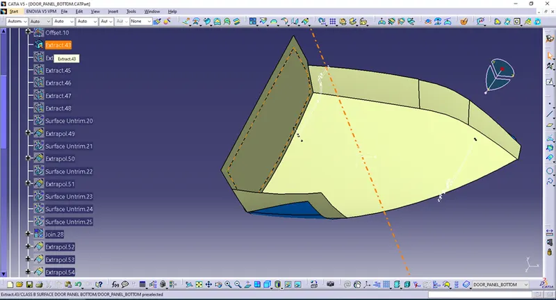
After I had surface untrimed and extrapolated all those extracted Surfaces I have trimmed them.
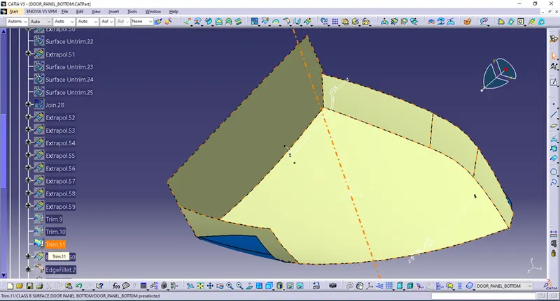
Then I have filleted offseted Surface regarding thicknes and offset direction.
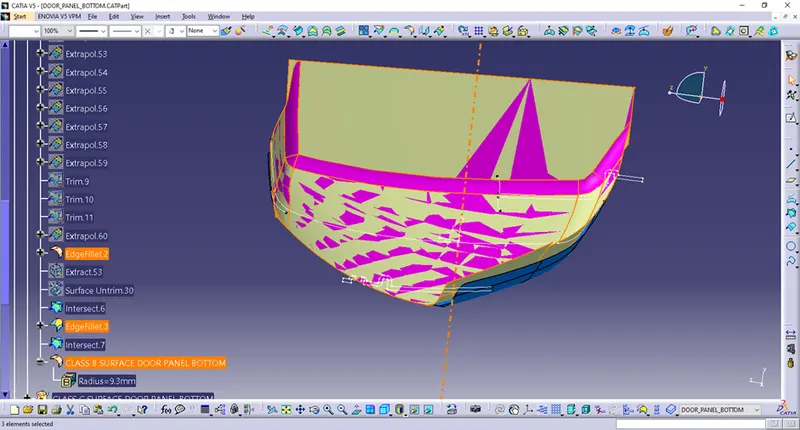
At the end of procedure I got needed CLASS_B_SURFACE_DOOR_PANEL_BOTTOM.
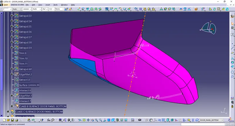
Now was time to design CLASS_C_SURFACE_DOOR_PANEL_BOTTOM under that Geometrical Set.I had to do Boundary on CLASS_A_SURFACE to make a Sweep on it,but that was impossible in one step,with one Boundary,that is why I had done it in more steps and more Sweeps and Trimmed them along the way.
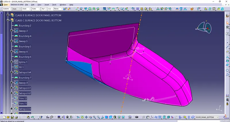
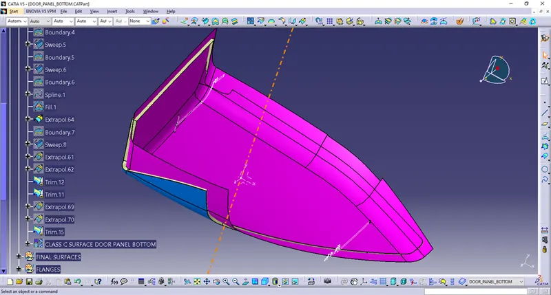
There is one place that should be taken in consideration and discussed with CLASS_A_SURFACE Engineer.Maybe is possible to do the CLASS_A_SURAFCE with a little inclination here.Then we could get a little bit more uniform thickness of the Part on that edge.
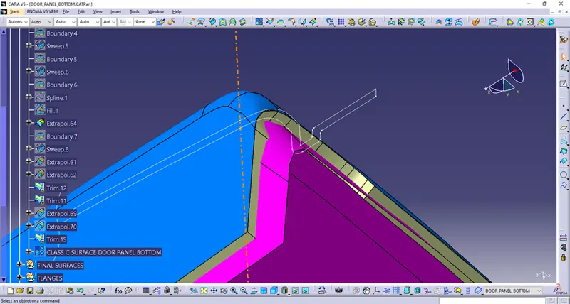
I have joined those Surfaces and form CLASS_C_SURFACE_DOOR_PANEL_BOTTOM that I needed.
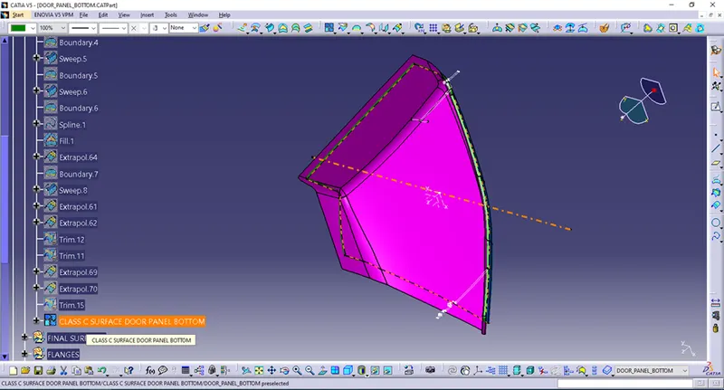
Now I had to form closed Surface of CLASS_A_SURFACE,
CLASS_B_SURFACE and CLASS_C_SURFACE.So,I had activated FINAL_SURFACE Geometrical Set with a Define in Work Object.
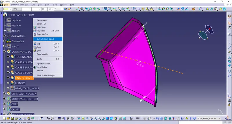
There I had joined first CLASS_A_SURFACE_DOOR_PANEL_BOTTOM and CLASS_C_SURFACE_DOOR_PANEL_BOTTOM.
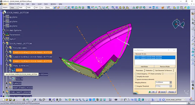
Then I have Trimmed that Join with CLASS_B_SURFACE_DOOR_PANEL_BOTTOM.
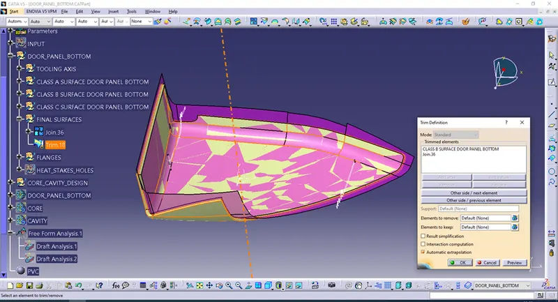
I had inserted new Body Part,renamed it as DOOR_PANEL_BOTTOM and there converted closed Surfaces from FINAL_SURFACE to Solid Part.
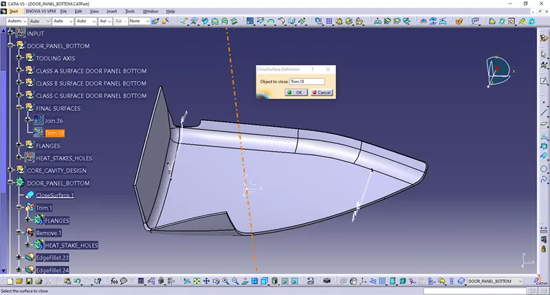
Now was time to do a Draft Analysis on Part also.
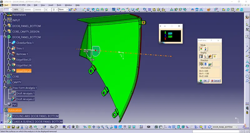
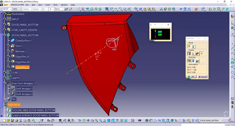
It can be seen,that in general Draft Analysis with that Tooling Axis is good,but there are a pair edges that should be changed in discussion with CLASS_A_SURFACE Support Engineer.
Here is also firts made Solid Part and then afterwards,in discussion about attachment strategy are added Attachment Features.
First are FLANGE_1 and FLANGE_2 Added to FLANGES Body (Boolean Operations) and then FLANGES are Union Trimmed to DOOR_PANEL_BOTTOM.
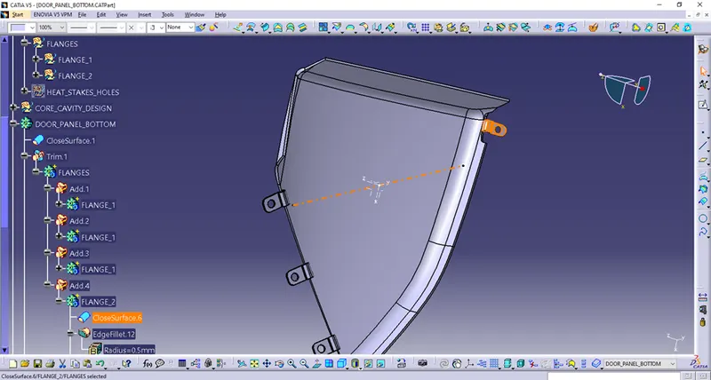
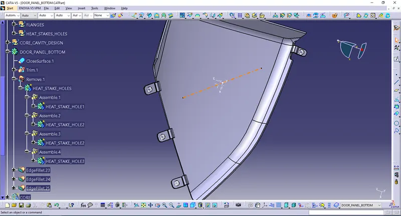
At the end I have Removed HEAT_STAKE_HOLES from the Part using HEAT_STEAK Geometry from the other Part in a DOOR Assembly and adjusting Geometry and inclination of HEAT_STAKE_HOLES to that HEAT_STAKES.Flange thickness is 2mm.The fillet of 0.3mm is applied on edges.
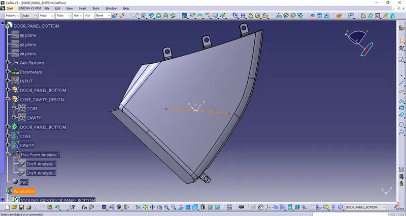
On the basis of constructed Part and Tooling Axis (Mold (Core&Cavity) moving direction and extraction of the Part) I had to construct CORE and CAVITY one more time.As before,under CORE_CAVITY_DESIGN Geometrical Set it was CORE and CAVITY Geometrical Sets given.
After I had extracted Surfaces of the Part it was done Boundary on those edges.
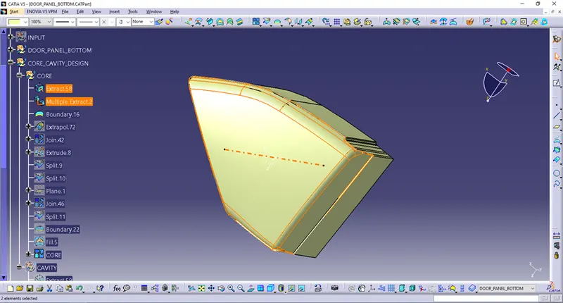
That Boundary I had extruded in Parts Tooling Axis direction.
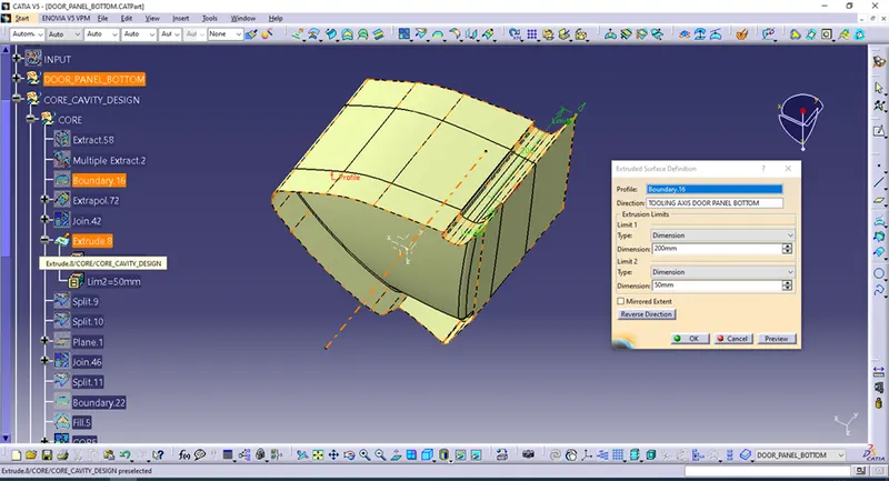
After some Splits,Fills and Joins closed Surface is formed.So,it was possible to close Surfaces and form Solid Part – CORE.
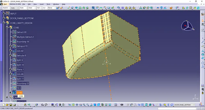
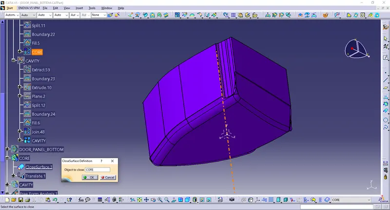
CORE Part is made in already inserted Body Part,and then translated for a 100mm.
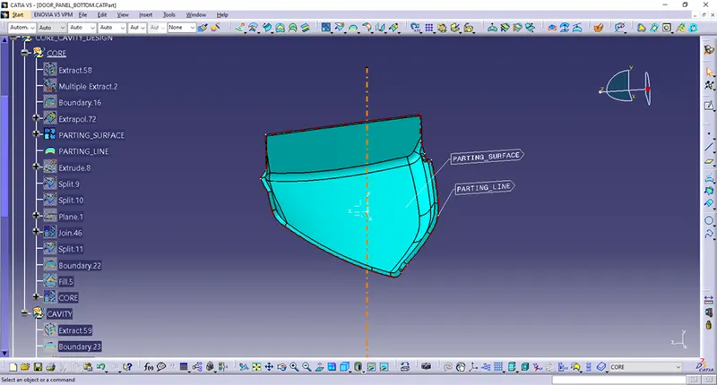
PARTING_SURFACE and PARTING_LINE Features are shown here,but as I already said,Part is done and we are making Mold Features but it should be discussed a inicial CLASS_A_SURFACE a little bit.With so inclined and defined CLASS_A_SURFACE there a problems and inconsistency in Part thickness at first and then in forming extruded and extrapolated Surfaces on boundaries.
The same procedure is done on CAVITY Part.In Cavity Geometrical Set are Surfaces of the Part extracted and done Boundaries on Extracts.
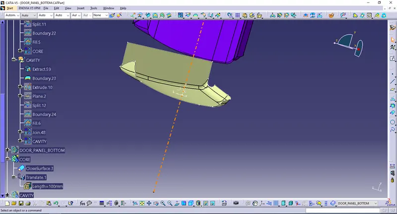
Then that Boundary is Extruded in Tooling direction.After that I have done some Splits,Fill and Joins in order to get closed form.
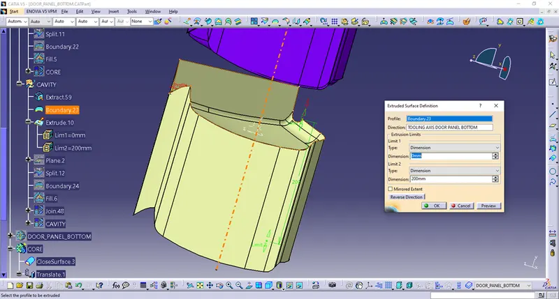
Finally I got CAVITY closed Surfaces that are possible to convert in Solid Parts.CAVITY Solid Part is translated for a 100mm in Tooling direction.
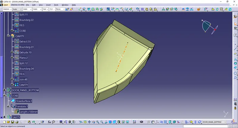
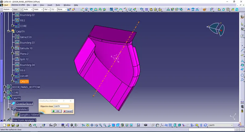
Parts with adjacent Features are given bellow.
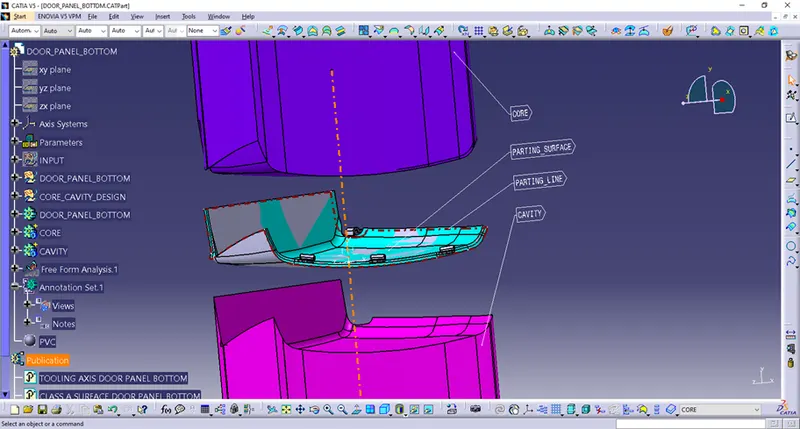
I had applied Material on the Part (PVC) and at the end I have Published all characteristic Features.
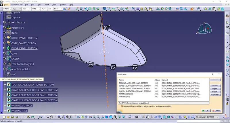
Now,when all the Parts were done,it was time to positioned them all in one Assembly.
So,first was opened a new Assembly and named MASTER_SECTION_DEVELOPMENT_SEPARATED_MODEL.In that Assembly I have inserted and fixed a Part MASTER_SECTION_DEVELOPMENT_INPUT that I got as an INPUT Step file.
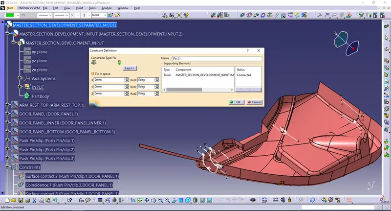
Then in that Assembly I have inserted all the Parts I had done – ARM_REST_TOP , DOOR_PANEL , DOOR_PANEL_INNER and DOOR_PANEL_BOTTOM and fixed them with constraints.
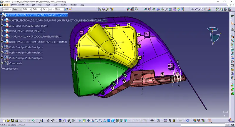
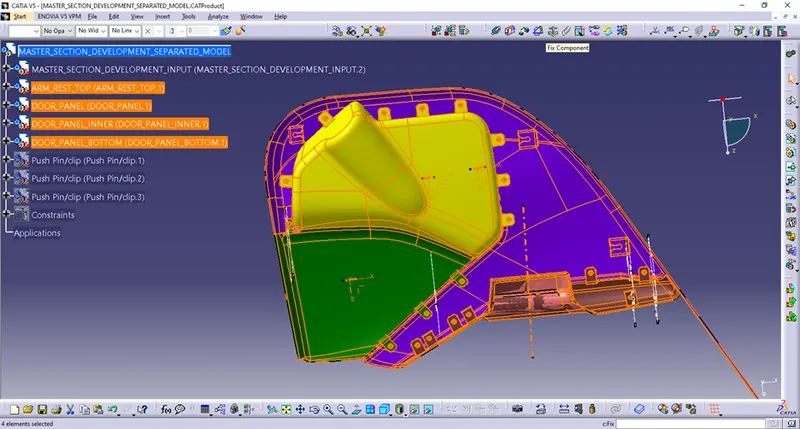
I had to check positions of all Parts with Attachment Features one to another.
When it is looked from above,normal to Tooling Axis all looks just fine and it is possible to approach to HEAT_STAKES in that direction with Tool to heat and pressure Heat Stakes with Flanges.
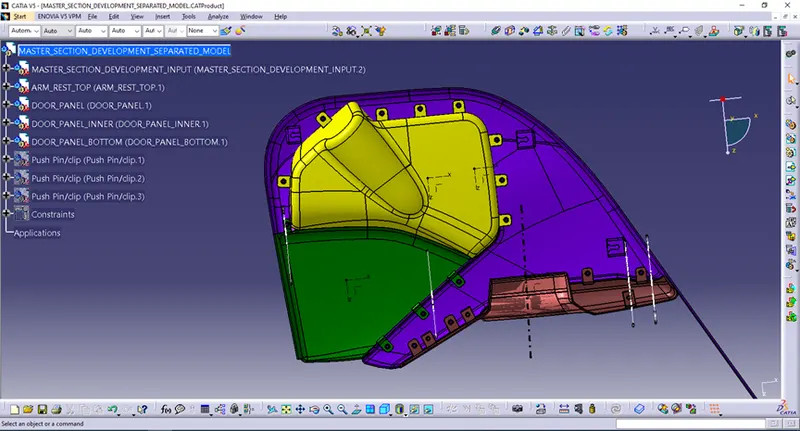
There are no collisions one Part to another,Dog Houses, Heat Stakes and Flanges are also good defined.
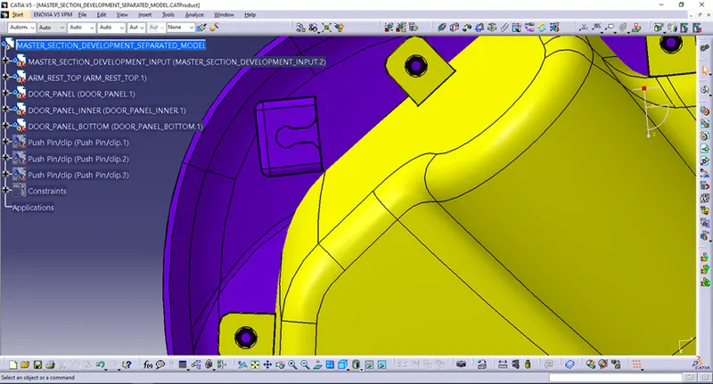
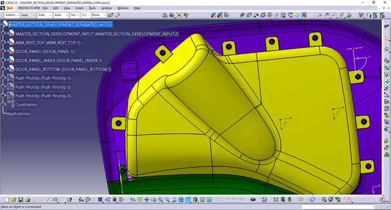
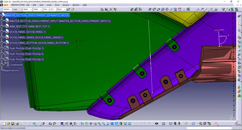
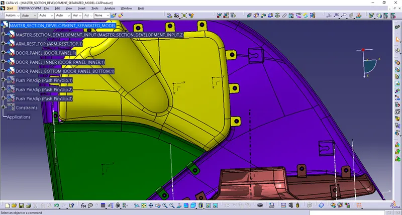
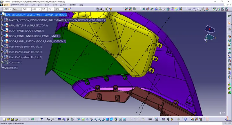
So,it can be seen that all Parts are good defined and positioned.Now it will be investigated Tooling Axis and Height of Heat Stakes in correlation to Flanges.
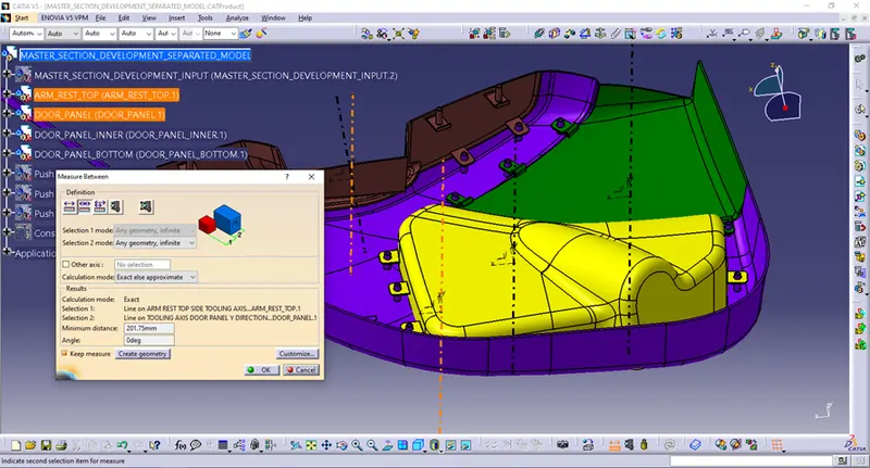
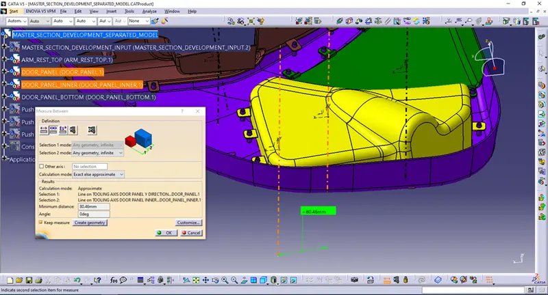
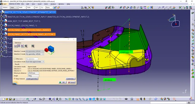
Investigation have shown that Parts are also good positioned according to Tooling Axis.
HEAT STAKE HOLES are designed in correlation to HEAT STAKES,that is why they correspond to each other.
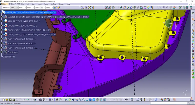
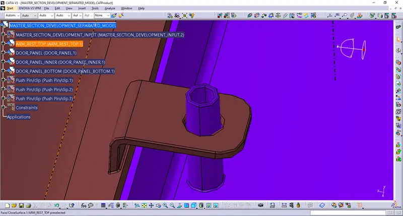
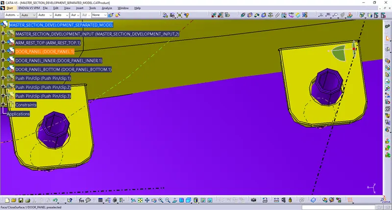
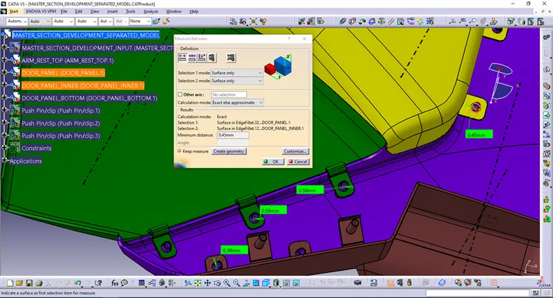
End the height of the HEAT STAKES is about 6mm.It satisfies also,there is enough material volume that could be heated and pressurised on FLANGES.
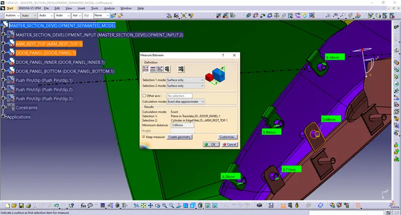
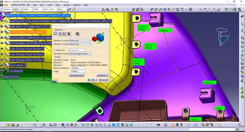
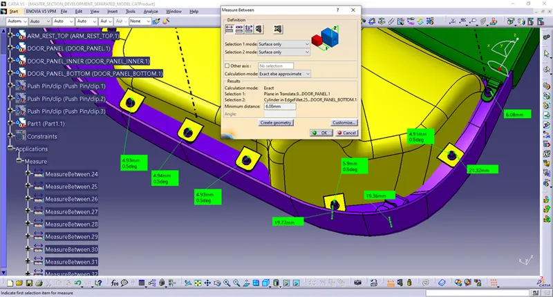
In all those images I hope I had shown,that there is no collision of parts and they are good positioned. The height,dimension overall and locations of them are well defined.
At the end,the Attachment strategy is with Push/Pin Parts defined.That is why I had DOG_HOSUSES so defined and constructed.With those Push/Pins it is possible our DOOR_PANEL ASSEMBLY attach and fix on BIW (Body in White – Car Body).
I have inserted Push/Pin Parts,that I as reference got in my Assembly MASTER_SECTION_DEVELOPMENT_SEPARATED_MODEL.The all other Parts are already there and fixed,after I have inserted Push/Pins,I had positioned those Parts in correlation to DOG_HOUSES.

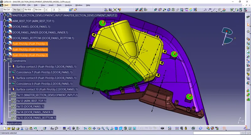
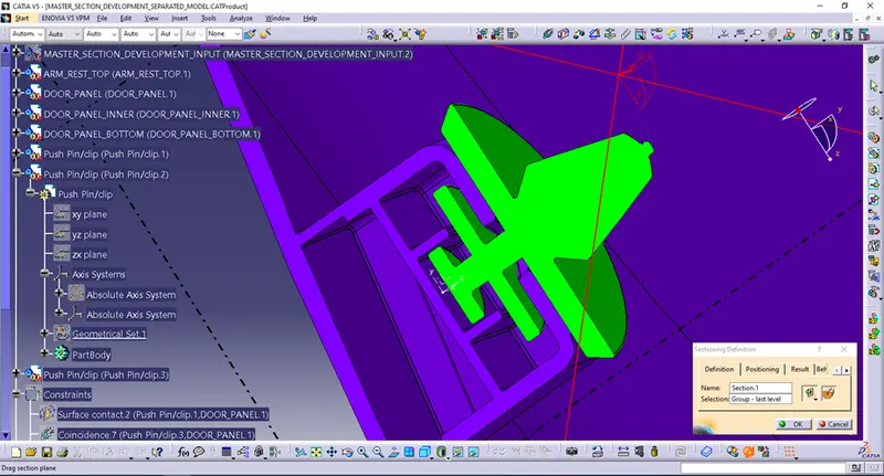
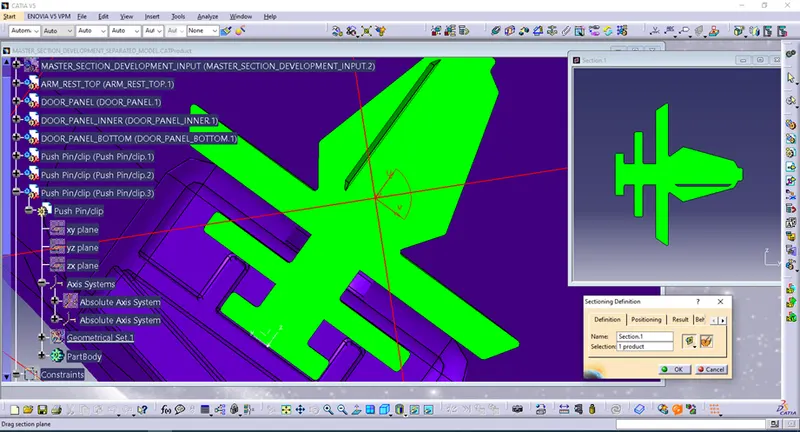
Final look of Assembly with all Parts and Attachment features is given bellow.
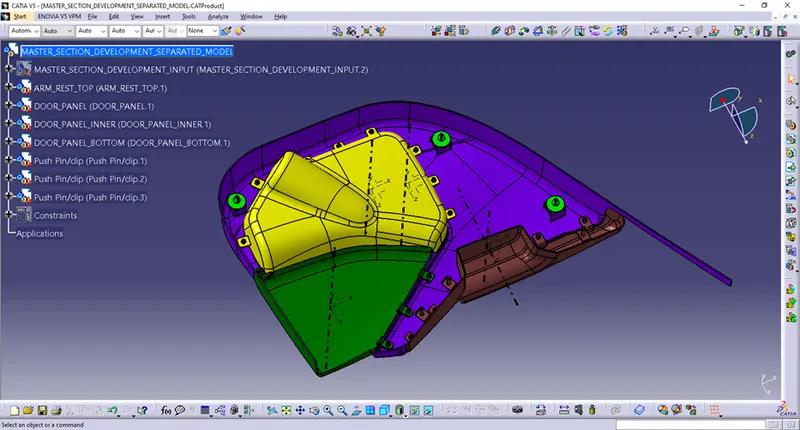
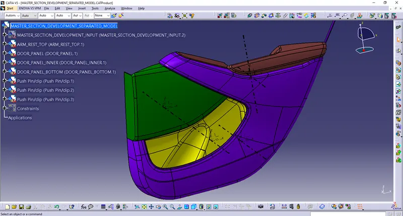
This very interesting and demanding challenge is coming to an end.There are some issues they should be discussed regarding CLASS_A_SURFACE.I have corrected some Surfaces.There is correlation with Parts and Mold (Core/Cavity) and we should take care about manufacturability and uniform thickness of Parts.
However,all is done in order to get Parts that could be manufactured,Draft Analysis on CLASS_A_SURFACES and Solid Parts are conducted and it is showed that Parts could be manufactured (in a later session I had directions regarding Heat Stakes and Flanges (Support Engineers have my gratitude,they were excellent)).After I had designed Parts and Core/Cavity ,I had to add Attachment Features also.I have checked then all the Parts and correlation of them,Attachment Features also,one in relation to other (Heat Stakes/Heat Holes/Flanges and Dog Houses/(Push/Pins).Between Tooling Axis of the Parts there are no inclinations (0deg measured) and there are no clashes between the Parts.With some corrections on CLASS_A_SURFACES and therefore Parts,the same could be produced and assembled.
FINALY I WANT TO THANK FOR THIS VERY INTERESTING PART OF COURSE.IN AUTOMOTIVE PLASTIC DESIGN COURSE I HAVE LEARNT A LOT (AND I HAVE MORE TO LEARN,THIS IS GOOD BEGINNING).
MANY THANKS TO SKILL-LYNC,THIS WAS VERY INTERESTING JOURNEY.
BEST REGARDS,
IVAN TOLE