Week 11 - Final project
DEVELOPMENT DOOR TRIM
AIM:-To create CAD model (DOOR TRIM ) considering CLASS A surface and normalising the thickness and Fixation strategy.
SUMMARY :- This project explains the complete life cycle of the product in an automotive industry particularlly the interior door trim or the plastic components used in the vehicle.The door trim is created using the CLASS A surface through wich the B surface is created and with the flanges C surface, having the daft angle followed in the automotive industries.Attachment features are also created following all the design rules and master section.
OBJECTIVE:-
- Create CAD model considering CLASS A surface and normalising the thickness and fixation strategy.
- Thicken the part with master section as refference.
- Tooling and draft analysis.
INTRODUCTION:-
10 stage product life cycle :-
- CONCEPT SKETCH
- STYLING CLASS A
- FEASIBILITY TEST
- CONCEPT VALIDATION
- NEW PRODUCT DESIGN
- PRODUCT DEVELOPMENT
- PROTO BUILD
- DESIGN VALIDATION
- PILOT PRODUCTION
- MASS PRODUCTION
PROCEDURE:-
- CLASS A SURFACE
In automotive industry one special team is there to create multiple concept sketches and one is finally used for NPD CAD and sent to the CAD engneering teams. NPD team will check if the design of CLASS A surface if it is manufactrable or it following the design principles.If there is any issue they ll ask the product team to check the CLASS A surface.
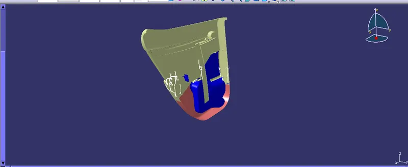
ARM REST:-
Initially i extracted the ARM REST and started working on the ARM REST as it is the most difficult and it can take the most of the time as i decided to extracted the CLASS A SURFACE of the ARM REST as shown below.
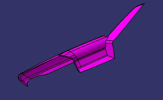
NEXT, main tooling axis of the CLASS A SURFCE by applying the bisecting method and create the tooling axis
NEXT, to check the quality of the surface so that it can be troubleshoot it, it is done by draft analysis as shown in the image below
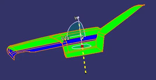
The center part is in blue colour i.e that particular area is in negative value nagative value which is fine no issue with it. Any area should not come in RED colour which means 0 degree draft.
B SURFACE DEVELOPMENT:-
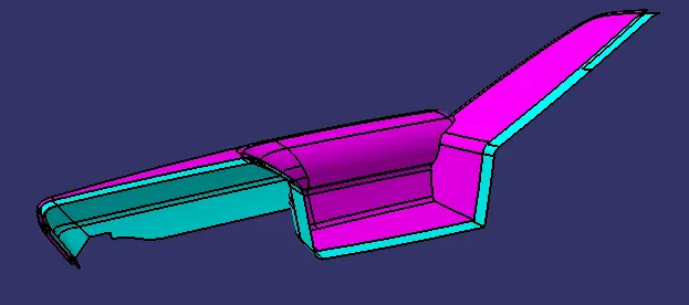
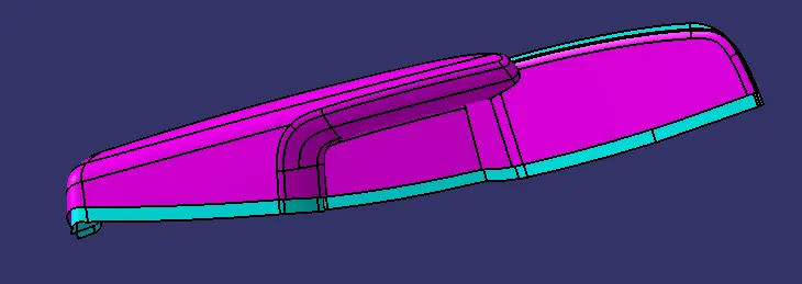
B surface was created using the A surface by offseting 2.5mm for thickenss
C SURFACE DEVELOPMENT:-
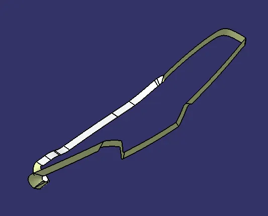
C surface was swept along the A surface with 'SWEEP' option at 3 degree draft angle outwards with respect to tooling direction.In some areas the MULTI SECTION SOLID is used at 90 degree values , as shown in the figure below
NEXT, CLASS A surface and sweep was joined together
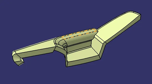
AFTER, joining the A surface with sweep the B SURFACE was trimmed with the A surface join to create the solid features.
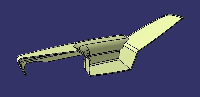
PART BODY is used to create the solid featurs in the final trim
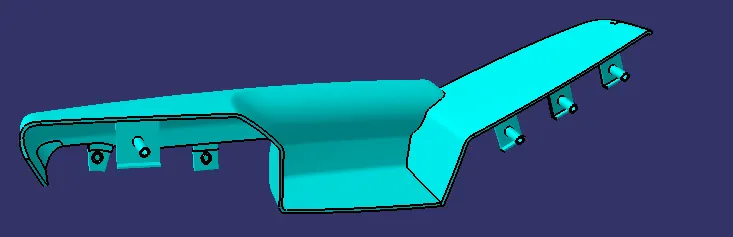
THEN, the final surface quality is checked with the draft analysis and there are some errors so the side core is given it ll be shown in the image below
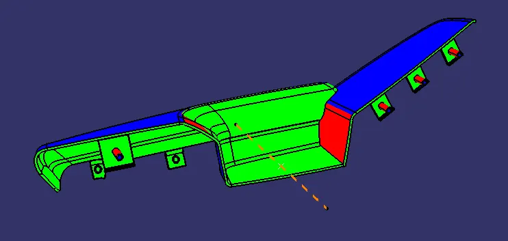
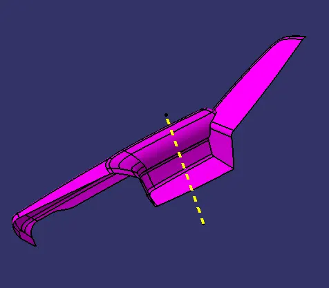
The main tooling axis is in yellow colour in the image below:-
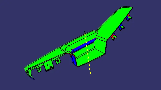
The above pictures shows the final draft analysis of the ARM REST.
MAP POCKET:-
A SURFACE
MAP POCKET was also created in the same way as the ARM REST was created , first to extract the CLASS A SURFACE of the map pocket as shown below:-
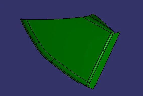
NEXT, Tooling axis was created for the component in this surfce the tooling axis is created at zero distance value as shown in the image below
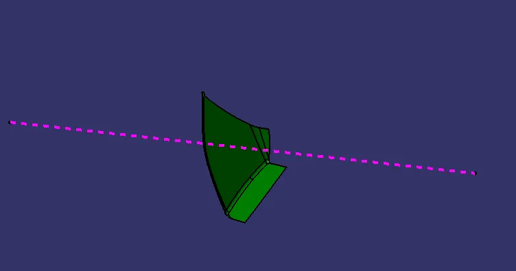
THEN, surface check was done to make sure the surface quality is fine and if there is any issue with the surface it should be troubleshooted at this stage to avoid errors
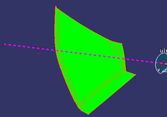
The surface quality of the part is good and can be proceed for further steps
B SURFACE DEVELOPMENT:-
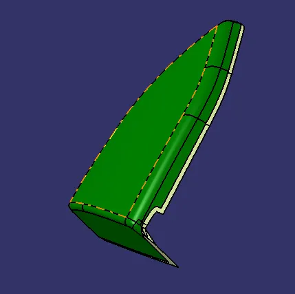
B surface is created by offseting the A surface to 2.5mm inside as shown in the image below:-
C SURFACE DEVELOPMENT:-
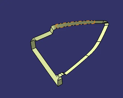
C surface was swept along the A surface with 'SWEEP' option at 3 degree draft angle outwards with respect to tooling direction.In some areas the MULTI SECTION SOLID is used at 90 degree values , as shown in the figure below:-
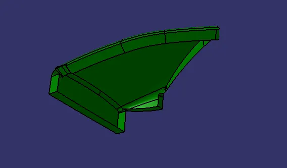
NEXT, CLASS A surface and sweep was joined together.
AFTER, joining the A surface with sweep the B SURFACE was trimmed with the A surface join to create the solid features.
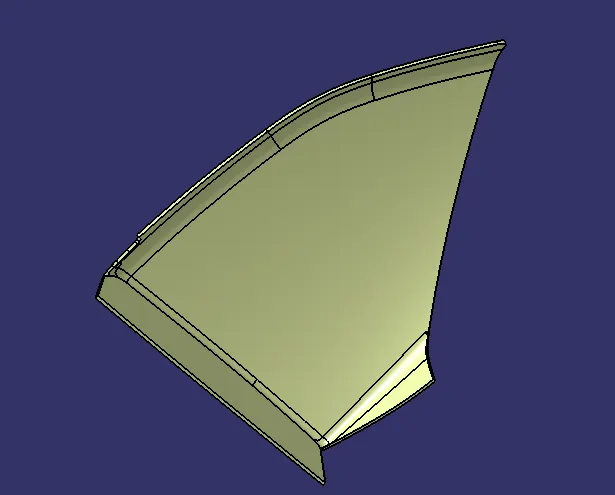
PART BODY is used to create the solid featurs in the final trim
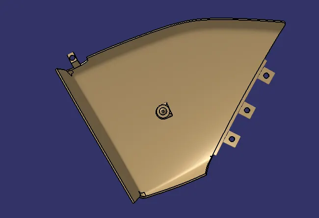
The final check is done with the draft analysis and the surface quality is good
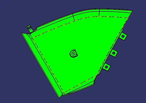
BOTTLE HOLDER:-
BOTTLE HOLDER was also created in the same way, first to extract the CLASS A SURFACE of the BOTTLE HOLDER as shown below:-
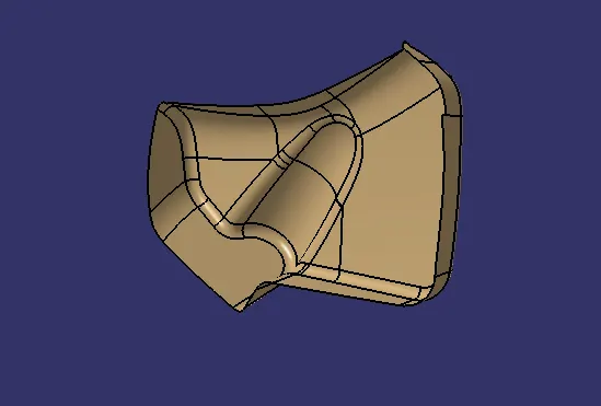
NEXT, Tooling axis was created for the component in this surfce the tooling axis is created at zero distance value as shown in the image below
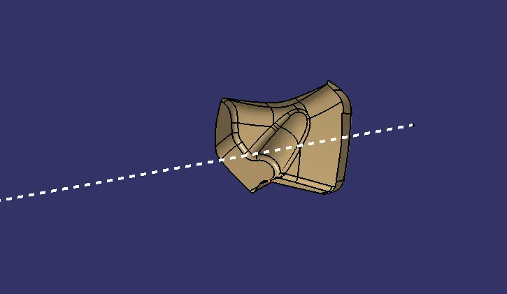
THEN, surface check was done to make sure the surface quality is fine and if there is any issue with the surface it should be troubleshooted at this stage to avoid errors
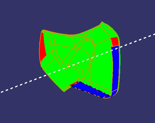
AS the quality of A surface of this part is not adequate so the final surface will also be the same problems so the class A surface designer should change the parts shown in the blue and red with some draft .
B SURFACE DEVELOPMENT:-
B surface is created by offseting the A surface to 2.5mm inside as shown in the image below:-
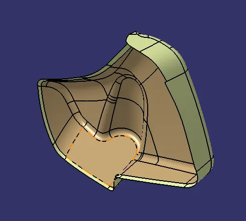
C SURFACE DEVELOPMENT:-
C surface was swept along the A surface with 'SWEEP' option at 3 degree draft angle outwards with respect to tooling direction.In some areas the MULTI SECTION SOLID is used at 90 degree values , as shown in the figure below:-
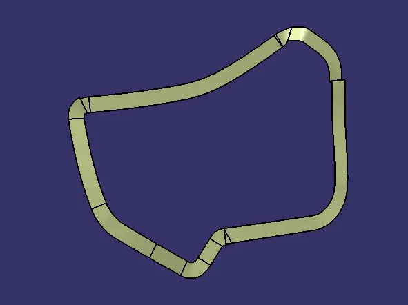
NEXT, CLASS A surface and sweep was joined together.
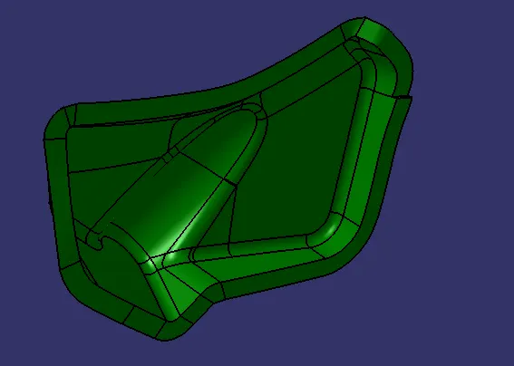
AFTER, joining the A surface with sweep the B SURFACE was trimmed with the A surface join to create the solid features.
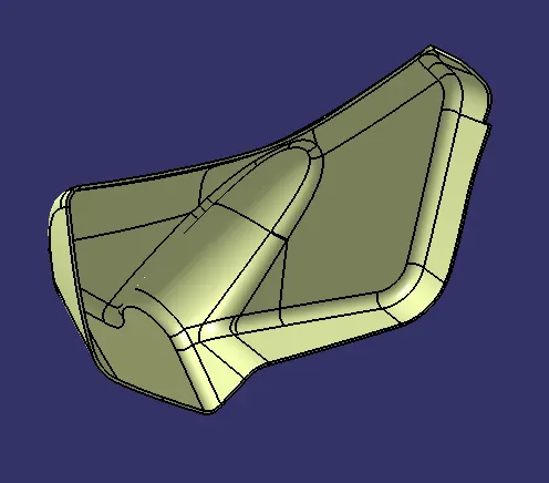
PART BODY is used to create the solid featurs in the final trim
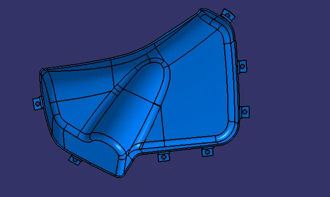
FINAL DRAFT ANALYSIS OF BOTTLE HOLDER
LOWER SUBSTRATE:-
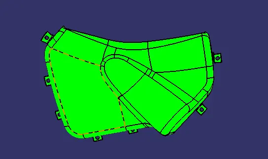
All the parts above are going to fixed on the lower substrate it was also created in the same way, first to extract the CLASS A SURFACE of the LOWER SUBSTRATE as shown below:-
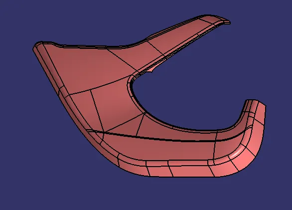
NEXT, Tooling axis was created for the component in this surface the tooling axis is created at zero distance value as shown in the image below
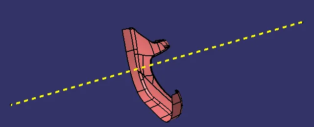
THEN, surface check was done to make sure the surface quality is fine and if there is any issue with the surface it should be troubleshooted at this stage to avoid errors
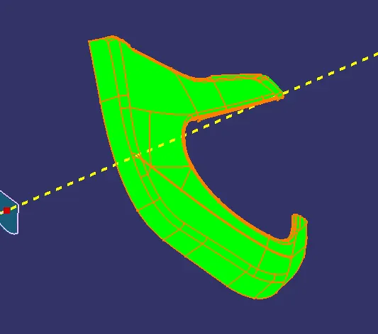
The surface quality of the part is good and can be proceed for further steps
B SURFACE DEVELOPMENT:-
B surface is created by offseting the A surface to 2.5mm inside as shown in the image below:-
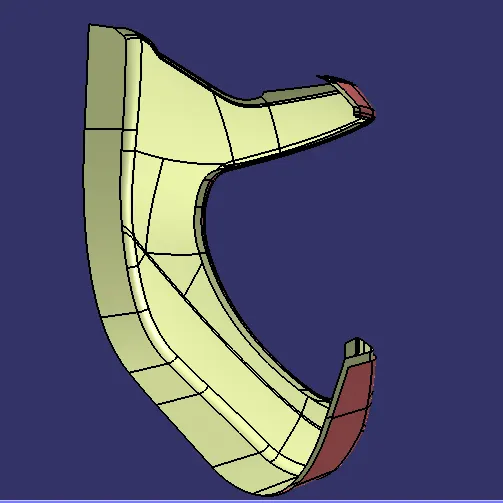
C SURFACE DEVELOPMENT:-
C surface was swept along the A surface with 'SWEEP' option at 3 degree draft angle outwards with respect to tooling direction.In some areas the MULTI SECTION SOLID is used at 90 degree values , as shown in the figure below:-
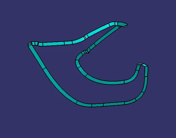
NEXT, CLASS A surface and sweep was joined together.
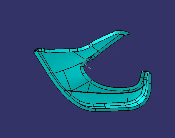
AFTER, joining the A surface with sweep the B SURFACE was trimmed with the A surface join to create the solid features.
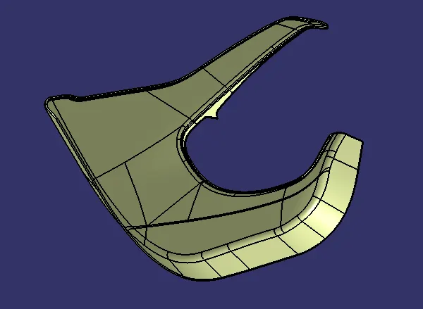
PART BODY is used to create the solid featurs in the final trim
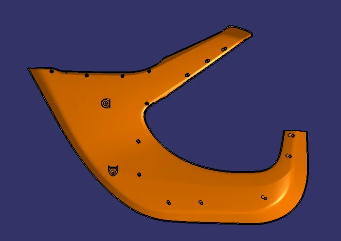
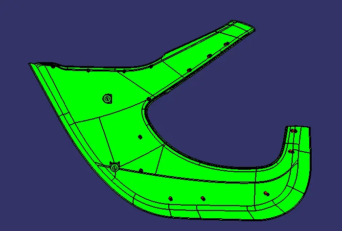
FINAL DRAFT ANALYSIS OF BOTTLE HOLDER
DOG HOUSE:-
DOG HOUSE is a engineering feature that allow the screwbose , pushclips and locators to provide height so that its easy to get fit in the sheet metal it has certain rules to follow to avoid the sinkmarks.
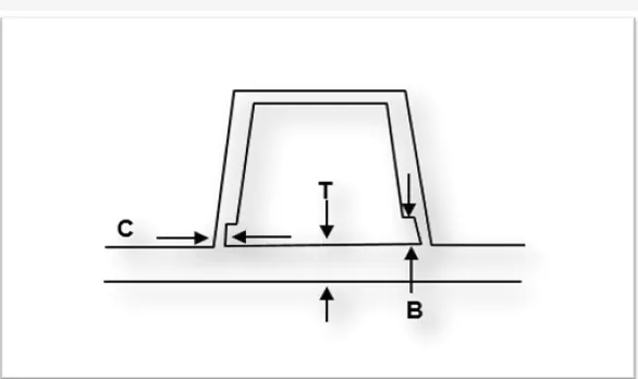
GENERAL GUIDEANCE FOR DOG HOUSE:-
- Dog house wall thickness at the intersection(C) must be 40% or less than main wall stock(T)
- Height of (B) should be 3.0-6.0mm
C is where the dog house comes in contact with backside surface
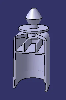
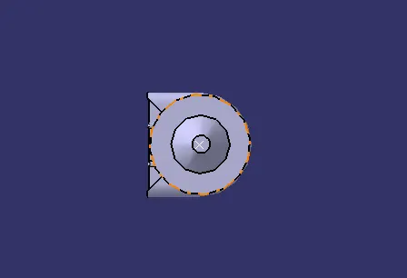
Draft analysis in main tooling and side core axis
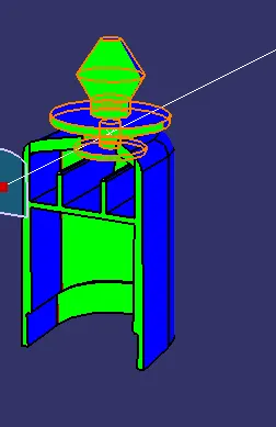
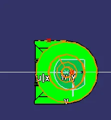
All the HEATSTAKES are having the draft angle of 0.5 degrees
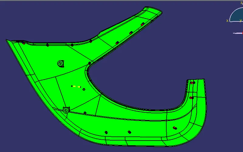
Draft analysis is successfully performed at minimum 3 degrees of draft angle
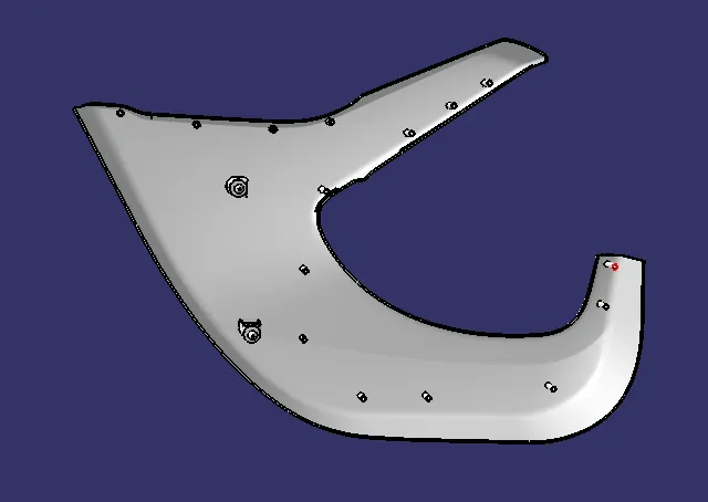
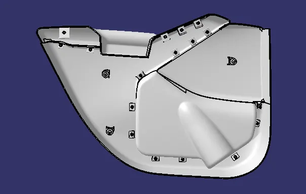
FINAL PRODUCT:-
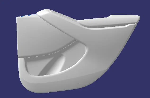
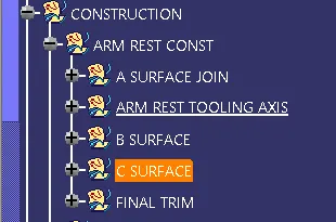
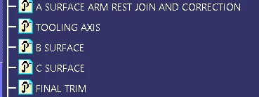
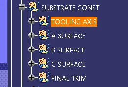
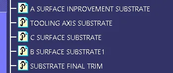
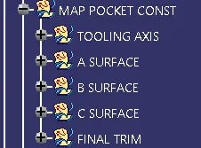
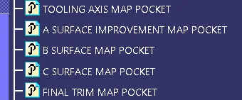
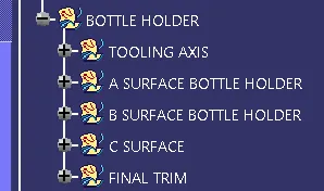
TREE STRUCTURE:-
ARM REST
LOWER SUBSTRATE
MAP POCKET
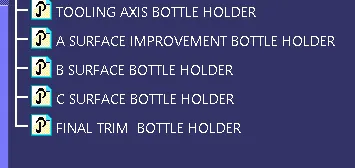
BOTTLE HOLDER
CONCLUSION:-
Door trim is successfully created using CLASS A and MASTER SECTION as input ,and draft analysis is successfully performed.