Week 8 - Challenge 2 - Base Bracket Design
DRAFT ANALYSIS REPORT
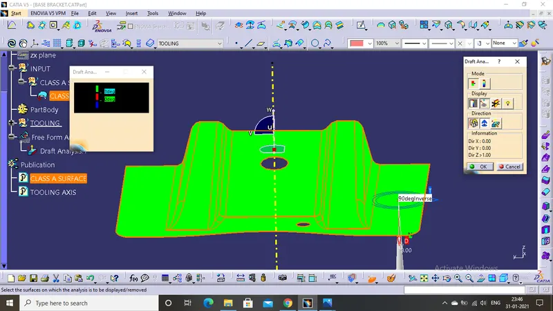
FIG 1.0
The above image( Fig 1.0) shows the draft analysis and the point shows the degree of draft of 90 degree to the particular base bracket in Z direction. The nominal value of draft is 3 degrees and the rough patch draft is 7 degrees and the side base bracket clears the both.
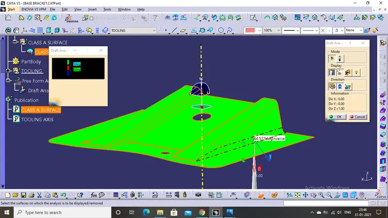
FIG 1.1
The above image( FIG 1.1) shows the draft analysis and the point shows the degree of draft of 44.57 degree to the particular side fillet in Z direction. The nominal value of draft is 3 degrees and the rough patch draft is 7 degree and the side fillet clears the both.
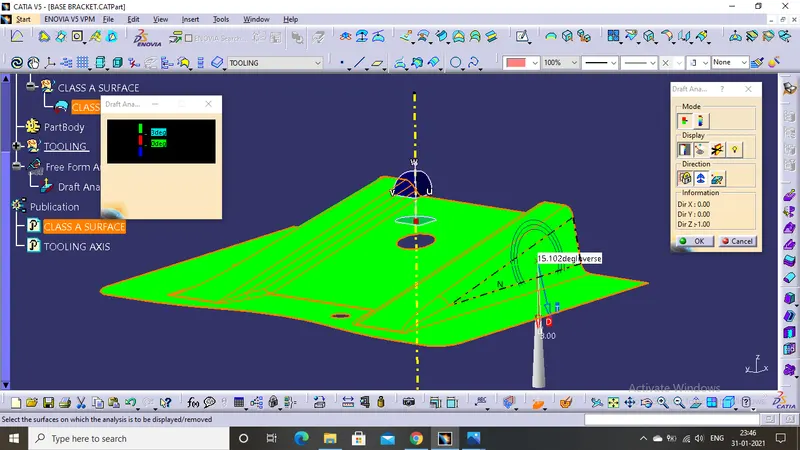
FIG 1.2
The above image( FIG 1.2) shows the draft analysis and the point shows the degree of draft of 15.1 degree to the particular RIB 1 in Z direction. The nominal value of draft is 3 degrees and the rough patch draft is 7 degree and the RIB 1 clears the both.
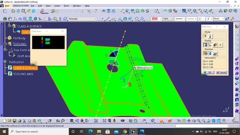
FIG 1.3
The above image( FIG 1.3) shows the draft analysis and the point shows the degree of draft of 43.68 degree to the particular RIB in Z direction. The nominal value of draft is 3 degrees and the rough patch draft is 7 degree and the RIB clears the both.
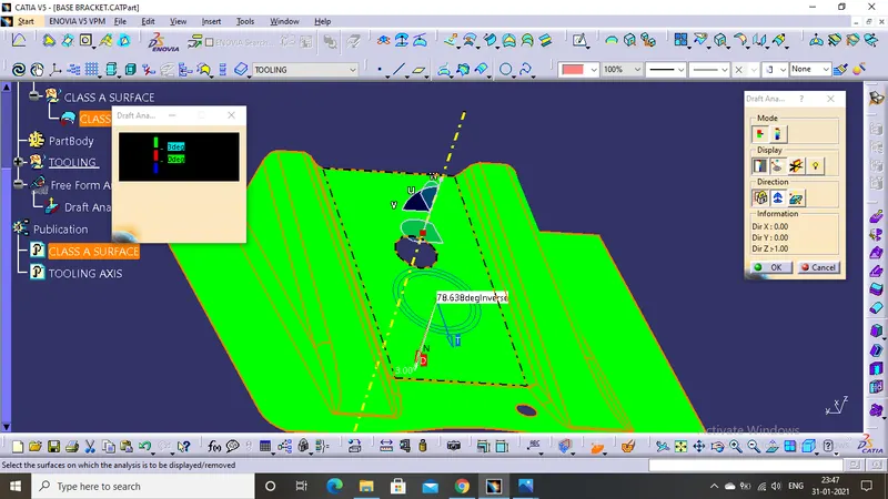
FIG 1.4
The above image( FIG 1.4) shows the draft analysis and the point shows the degree of draft of 78.63 degree to the particular BASE in Z direction. The nominal value of draft is 3 degrees and the rough patch draft is 7 degree and the BASE clears the both.
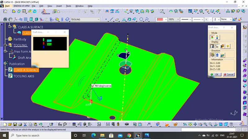
FIG 1.5
The above image( FIG 1.5) shows the draft analysis and the point shows the degree of draft of 67.98 degree to the particular SIDE WALL RIB in Z direction. The nominal value of draft is 3 degrees and the rough patch draft is 7 degree and the SIDE WALL RIB clears the both.
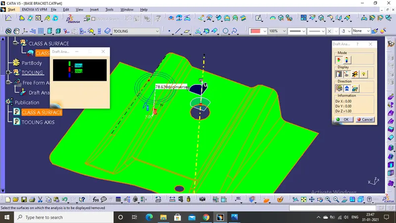
FIG 1.6
The above image( FIG 1.5) shows the draft analysis and the point shows the degree of draft of 78.63 degree to the particular TOP WALL RIB in Z direction. The nominal value of draft is 3 degrees and the rough patch draft is 7 degree and the TOP WALL RIB clears the both.
*****************************************************************************************************************************************************
CLOSE SURFACE DRAFT ANALYSIS
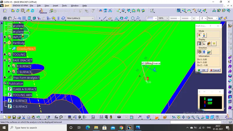
FIG 2.0
The above image( FIG 2.0) shows the draft analysis of close body surface and the point shows the degree of draft of 60.58 degree to the particular SIDE FILLET in Z direction. The nominal value of draft is 3 degrees and the rough patch draft is 7 degree and the SIDE FILLET clears the both.
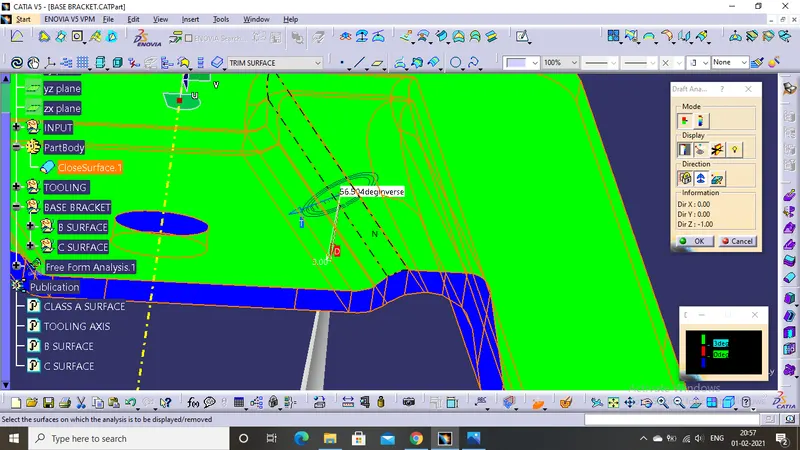
FIG 2.1
The above image( FIG 2.1) shows the draft analysis of close body surface and the point shows the degree of draft of 56.9 degree to the particular RIB in Z direction. The nominal value of draft is 3 degrees and the rough patch draft is 7 degree and the RIB clears the both.
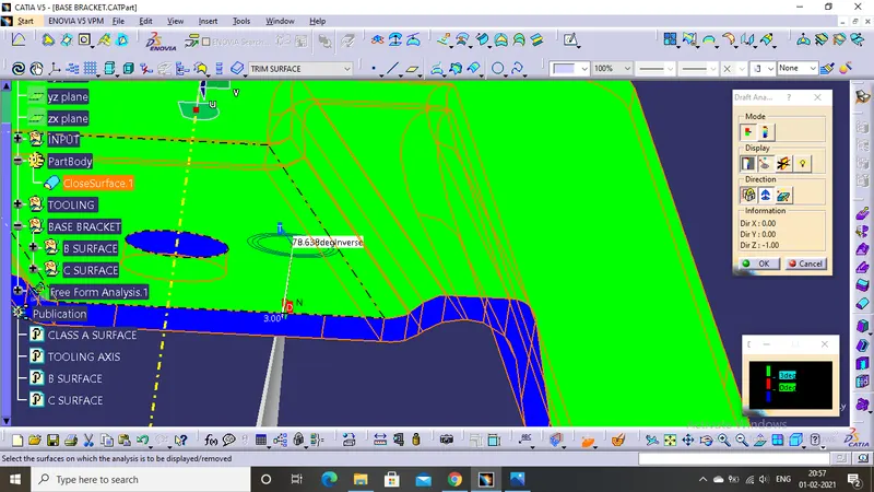
FIG 2.2
The above image( FIG 2.2) shows the draft analysis of close body surface and the point shows the degree of draft of 78.63 degree to the particular BASE in Z direction. The nominal value of draft is 3 degrees and the rough patch draft is 7 degree and the BASE clears the both.
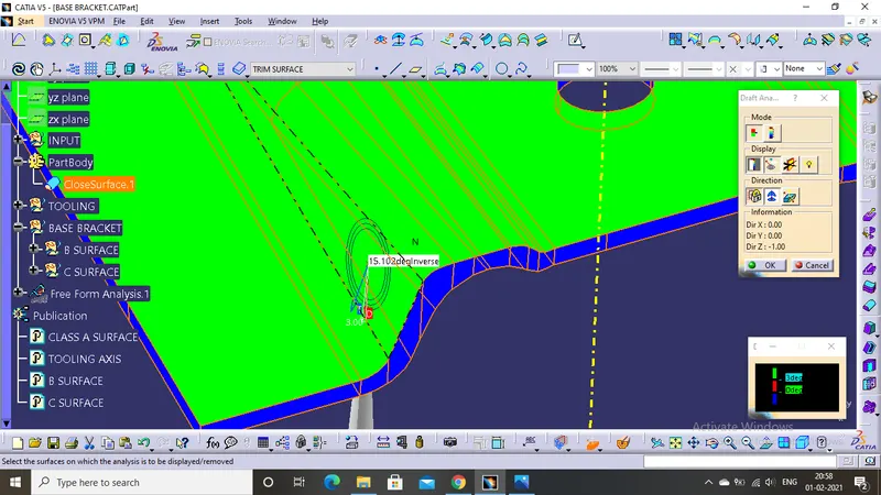
FIG 2.3
The above image( FIG 2.3) shows the draft analysis of close body surface and the point shows the degree of draft of 15.10 degree to the particular RIBin Z direction. The nominal value of draft is 3 degrees and the rough patch draft is 7 degree and the RIB clears the both.
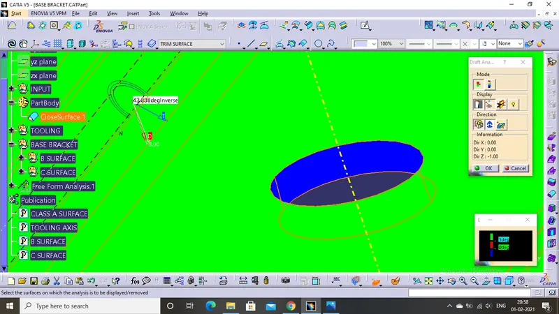
FIG 2.4
The above image (FIG 2.4) shows the draft analysis of close body surface and the point shows the degree of draft 43.98 to the particular RIB in Z direction, and the hole in the part is created by using the sweep command under sweep command with the option of WITH DRAFT DIRECTION and the draft angle is given as 3 degree .Thus the close body clears the nominal draft value of 3 degree and the rough value of 7 degree.
*****************************************************************************************************************************************************
DRAFT TOOL EXPLAINATION
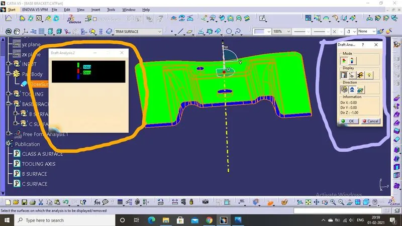
FIG 3.0
The above image (FIG 3.0 ) shows the DRAFING TOOLS in which the tool in the orange colour circle shows the limit of the draft angle and the tool in the right side shows the different commands or the operation . These tools also show the large table of the degree limits. The green colour shows the positive value and the RED colour shows the 0 degree value , while the BLUE colour shows the negative or reverse value . Both GREEN and BLUE colour are correct.
*****************************************************************************************************************************************************
TOOLING AXIS
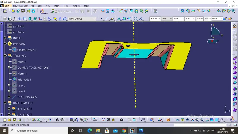
FIG 4.0
The above image ( FIG 4.0) shows the TOOLING AXIS of the BASE BRACKET in which the axis is created by using a point , dummy tooling axis , intersect, lines . First check for the clearance and then proceed for the intersect part and intersect the bracket with the plane and to get the sketch of the portion and extend it very well after that use the line command and use the bisecting line command select the lines and the point to create the bisecting line. The bisecting is the TOOLING AXIS of the component.'
*****************************************************************************************************************************************************
DIFFERENT VIEWS
FRONT VIEW
SIDE VIEW
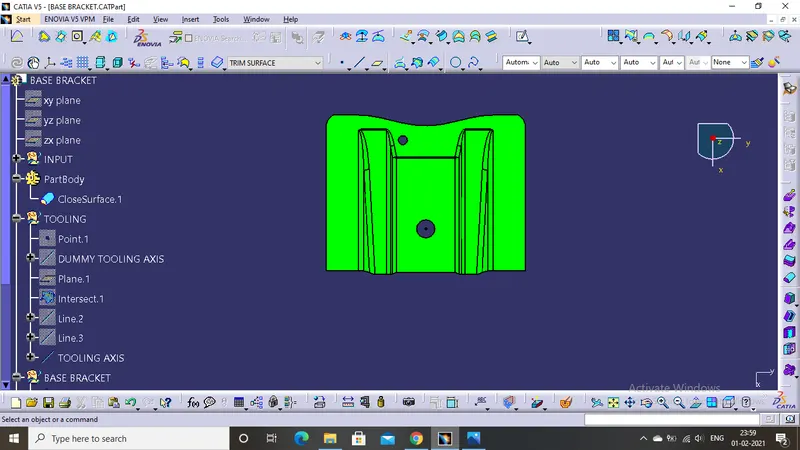
TOP VIEW
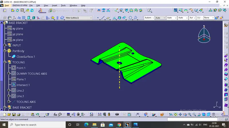
ISOMETRIC VIEW