Week 8 - Challenge 4 - Coin Holder Design
COIN HOLDER
DRAFT ANALYSIS
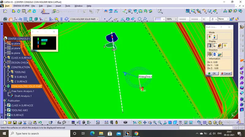
FIG 1.0
The above image (FIG 1.0) shows the base of the coin holder with a draft of 90 degree and it clears the nominal draft of 2.8 degree and rought patch draft of 7 degree. Hence the base is ready for manufacturing.
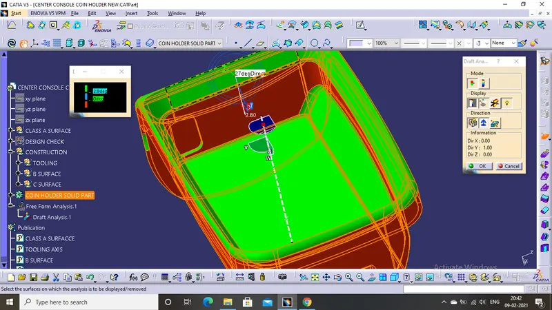
FIG 1.1
The above image(FIG 1.1) shows the top wall of the coin holder with a draft of 27 degree and it clears the nominal draft of 2.8 degree and rought patch draft of 7 degree. Hence the top wall is ready for manufacturing.
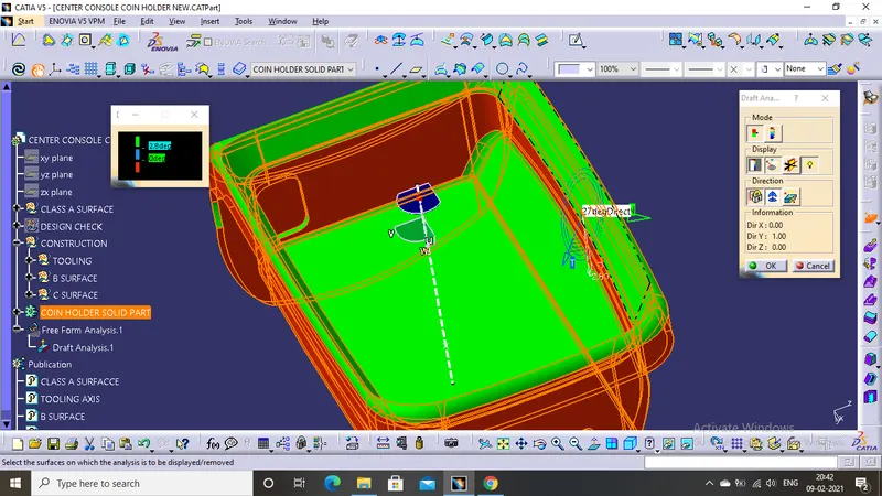
FIG 1.2
The above image(FIG 1.2) shows the top wall of the coin holder with a draft of 27 degree and it clears the nominal draft of 2.8 degree and rought patch draft of 7 degree. Hence the top wall is ready for manufacturing.
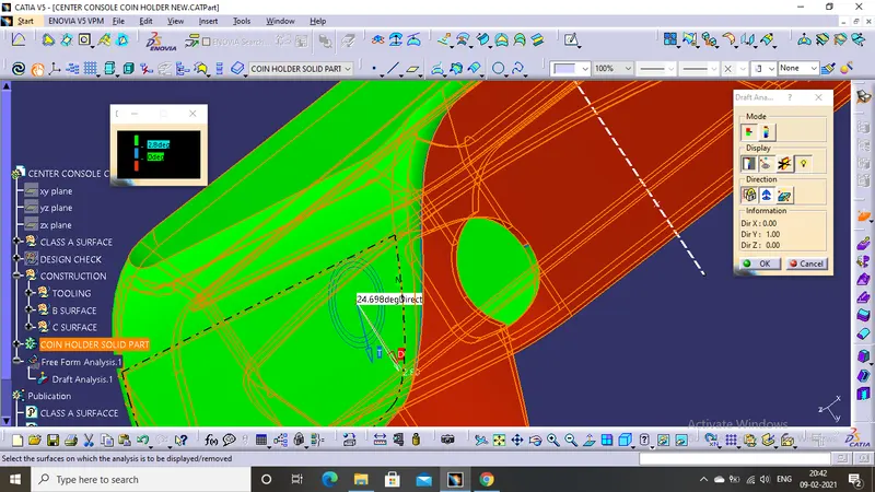
FIG 1.3
The above image(FIG 1.3) shows the outside flinges of the coin holder with a draft of 24.69 degree and it clears the nominal draft of 2.8 degree and rought patch draft of 7 degree. Hence the outside flinges is ready for manufacturing.
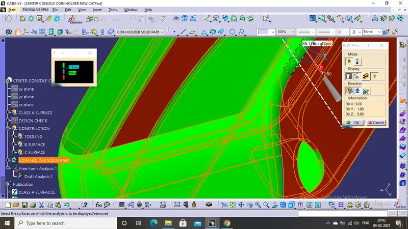
FIG 1.4
The above image(FIG 1.4) shows the outside fillet of the coin holder with a draft of 36.17 degree and it clears the nominal draft of 2.8 degree and rought patch draft of 7 degree. Hence the outside fillet is ready for manufacturing.
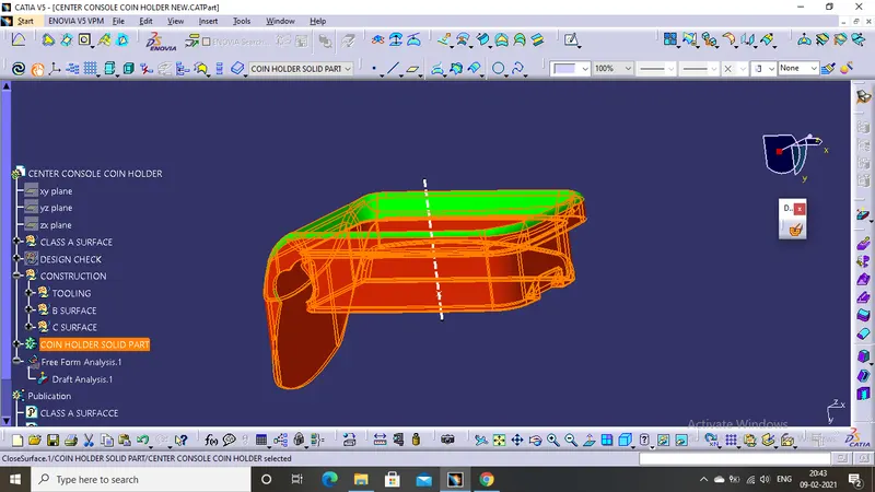
FIG 1.5
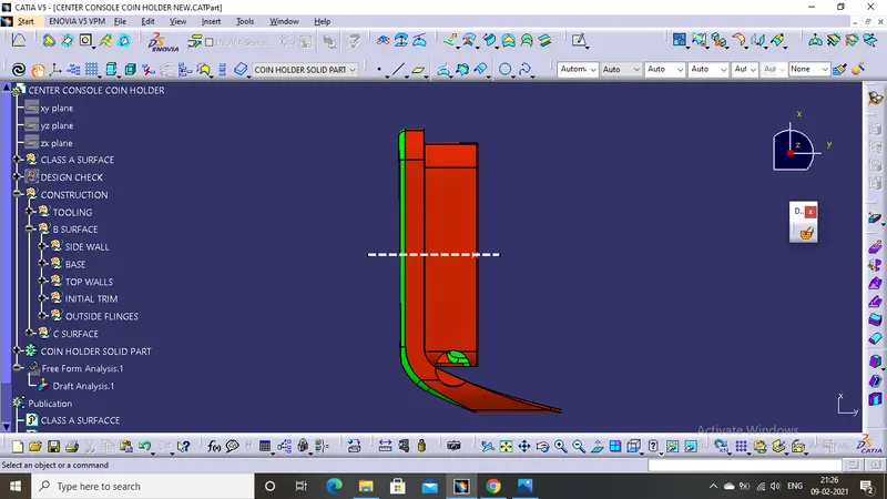
The above image (FIG 1.5) shows some area of the part in red colour and some area in gree colour .Red colour area indicates the negative value of draft angle it is because the CLASS A surface does not have the draft angle , so in draft analysis the part appears in red,still the part can go under manufacturing but the construction of core and cavity will be bit costlier.
*****************************************************************************************************************************************************
DRAFT TOOLS
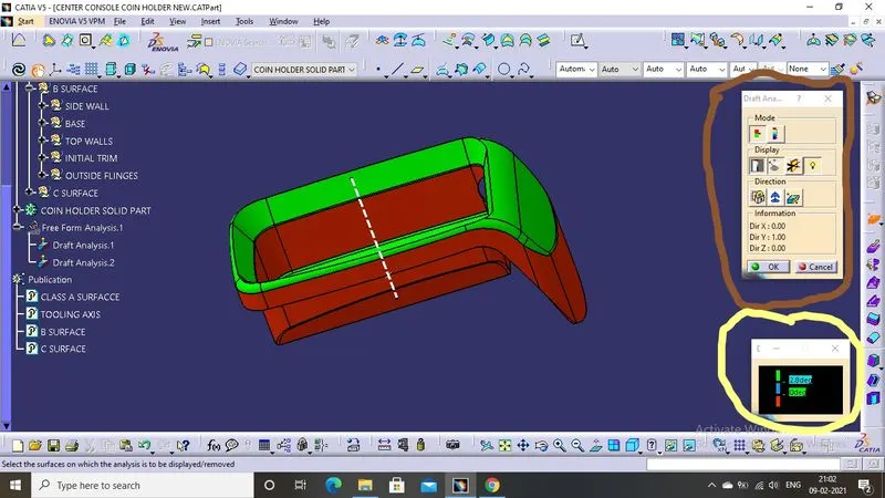
Above image shows the DRAFT ANALYSIS TOOLS in which the BROWN circle shows the direction , things to display like draft analysis under the running point,low light option etc and at top it shows MATERIAL MODES .
YELLOW circle shows the nominal draft values , GREEN means the area is above the nominal draft angle, BLUE shows the zero degree draft and the RED shows the negative draft values or the reversedraft values.
*****************************************************************************************************************************************************
TOOLING AXIS
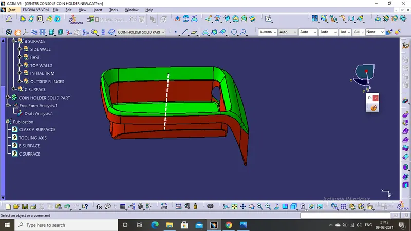
In above image the white line in the middle of the part is the TOOLING AXIS and it also defines the opening and closing of the core and cavity. In this particular part the TOOLING AXIS is at 90 degrees because there is no draft angle is present in CLASS A SURFACE.
*****************************************************************************************************************************************************
DIFFERENT VIEWS
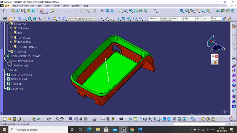
ISOMETRIC VIEW
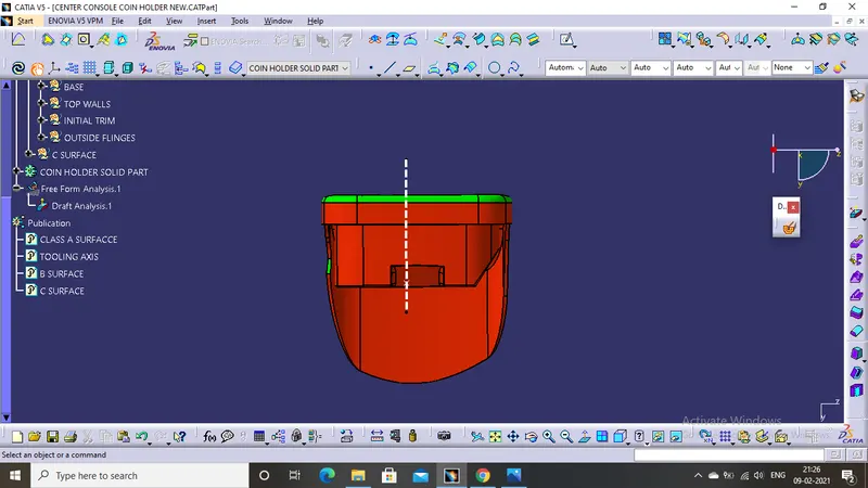
FRONT VIEW
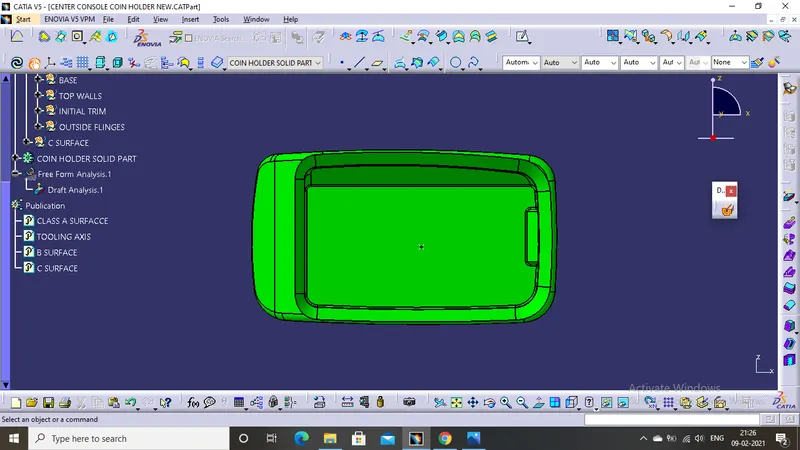
TOP VIEW
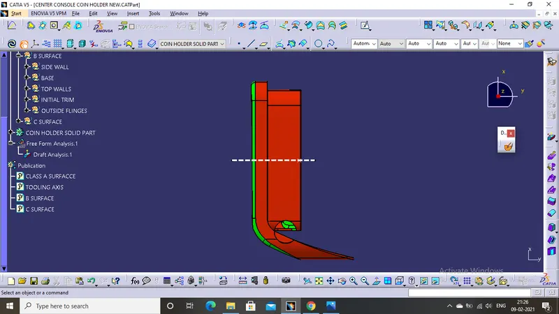
SIDE VIEW
*****************************************************************************************************************************************************
TREE STRUCTURE