Week 8 - Challenge 1 - Draft Analysis on a Fan Cover
DRAFT ANALYSIS REPORT
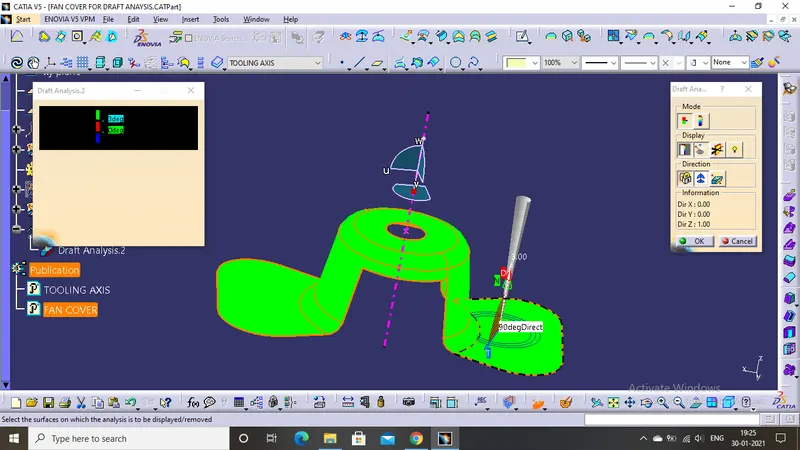
FIG:- 1.0
The above image(fig 1.0) shows the value of the side cover which is 90 degree along the Z direction , which means the side cover is ready to indergo the tooling with the help of injection moulding or any other manufacturing process.
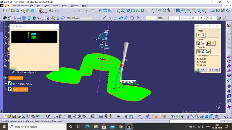
FIG 1.1
The above image (fig 1.1) shows the draft angle of 9.195 degree along Z direction , which means the pannel clears the nominal draft angle of 3 degree and also clears the rough patch tooling draft angle of 7 degree.The pink line shows the TOOLING AXIS.
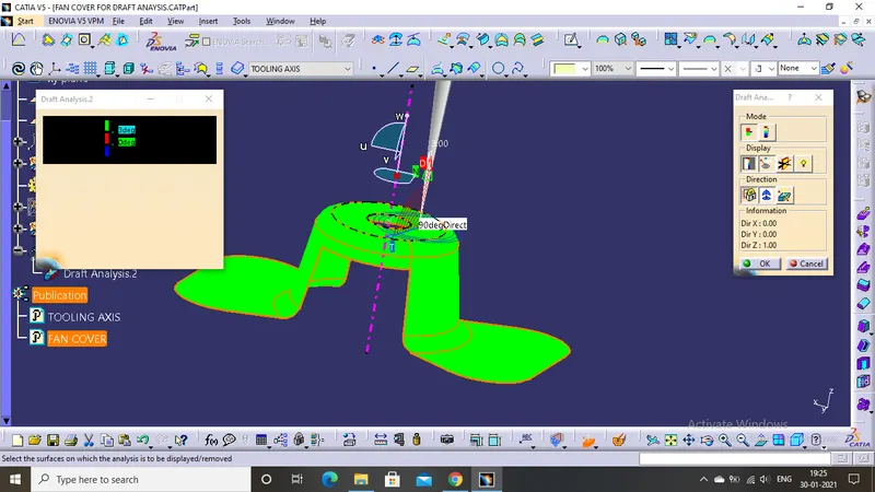
FIG 1.2
The ablove image (fig 1.2) shows the draft angle of the top surface which is 90 degree in Z direction, which means the top surface clears the nominal draft angle of 3 degree and also clear the angle of rough patch of 7 degree and is ready for TOOLING AXIS .The pink line is the TOOLING AXIS.
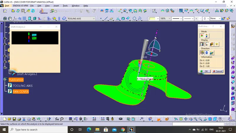
FIG 1.3
The above image (fig 1.3) shows the draft angle of 9.195 degree along Z direction , which means the pannel clears the nominal draft angle of 3 degree and also clears the rough patch tooling draft angle of 7 degree.The pink line shows the TOOLING AXIS.
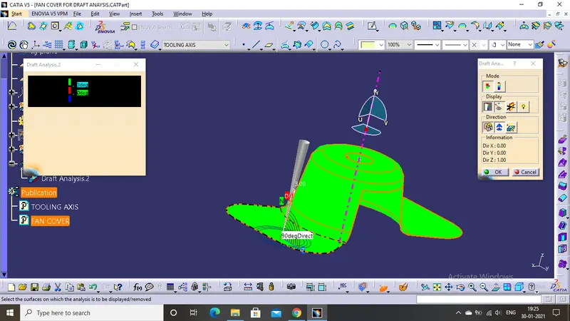
FIG 1.4
The above image(fig 1.4) shows the value of the side cover which is 90 degree along the Z direction , which means the side cover is ready to indergo the tooling with the help of injection moulding or any other manufacturing process.The pink line shows the TOOLING AXIS.
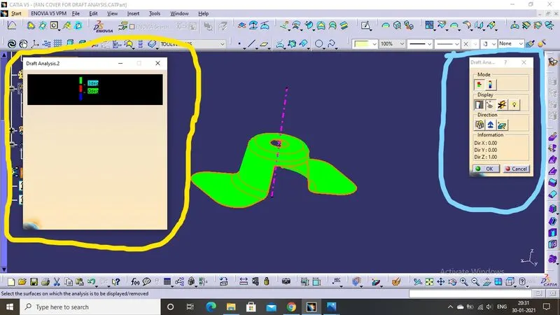
FIG 1.5
The above image (fig 1.5) shows the drafting tools , the circle in left with yellow colour shows different draft angle which is GREEN shows the part is above 3 degree draft angle and is ready for tooling .
RED shows the 0 degree darft angle and the part will affect the CORE AND CAVITY while ejecting, which will damage the part aswell as the mould.
BLUE shows the negative value of the draft angle and the part will appeare in blue or we can say that the part is not toolable.
*****************************************************************************************************************************************************
BISECTING METHOD
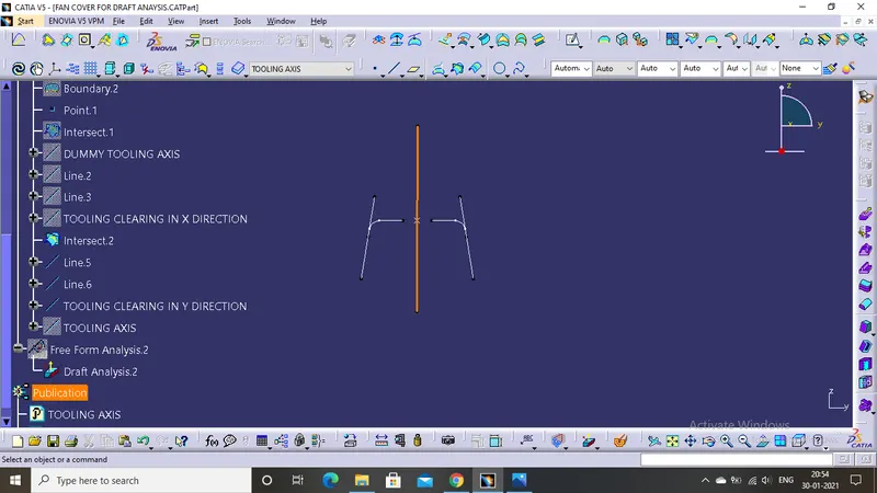
FIG 2.0
The above image ( fig 2.0 ) shows the bisecting line in amber colour with the reference of two with the point to point connection and the purpose of these lines is to make sure the part is clearing the tooling in the defined direction. In the above image the tooling is cleared in Y direction. The two curves seen in the image is the sketch created with the help of intersection command.
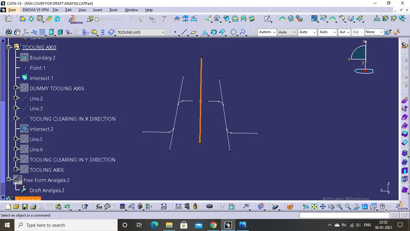
FIG 2.1
The above image ( fig 2.1) shows the bisecting line in amber colour with the reference of two with the point to point connection and the purpose of these lines is to make sure the part is clearing the tooling in the defined direction. In the above image the tooling is cleared in X direction. The two curves seen in the image is the sketch created with the help of intersection command.
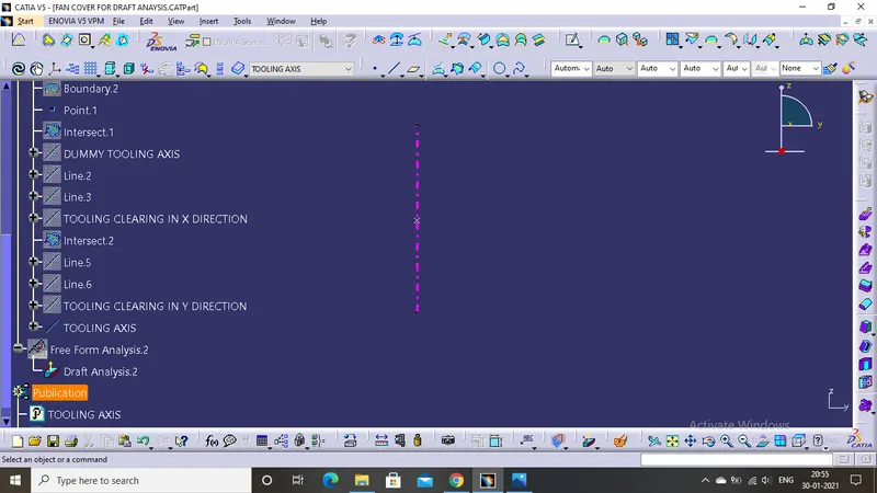
FIG 2.2
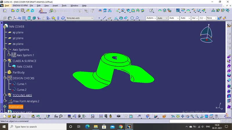
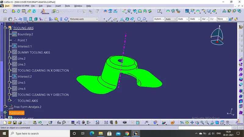
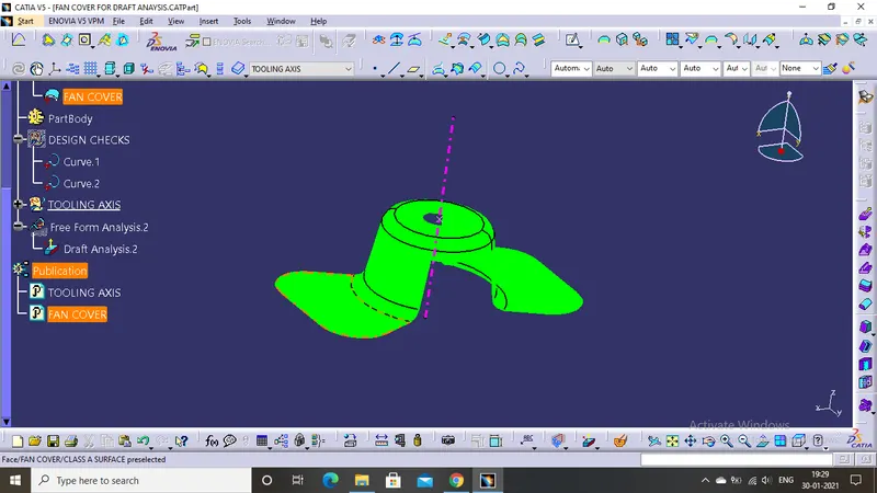
The above image (fig 2.2) shows the line in pink colour represents the TOOLING AXIS which is in Z direction and is created by with the TOOL CLEARING X DIRECTION and TOOL CLEARING Y DIRECTION.
*****************************************************************************************************************************************************
DIFFERENT VIEWS
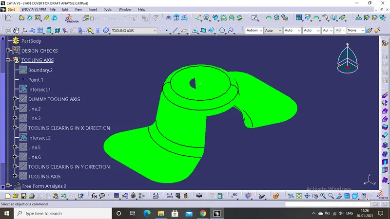
FIG 3.1 ISOMETRIC VIEW
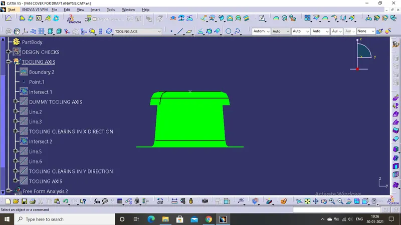
FIG 3.2 FRONT VIEW
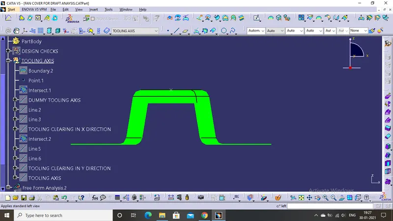
FIG 3.3 SIDE VIEW
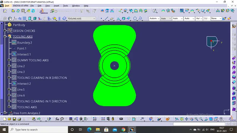
FIG 3.4 TOP VIEW
*****************************************************************************************************************************************************
TREE EXPANSION