Week 11 - Final project
HELLO SIR,
Week 11 - Final project
OBJECTIVE:-
To design the following requirement for the given class A surface and master section sketch.
- Tooling Axis creation & Draft analysis
- Class B surface & class C surface
- Close Body and thicken part
- Creation of additional engineering features.
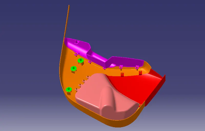
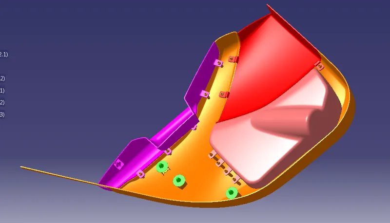
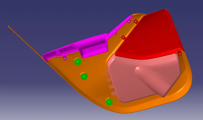
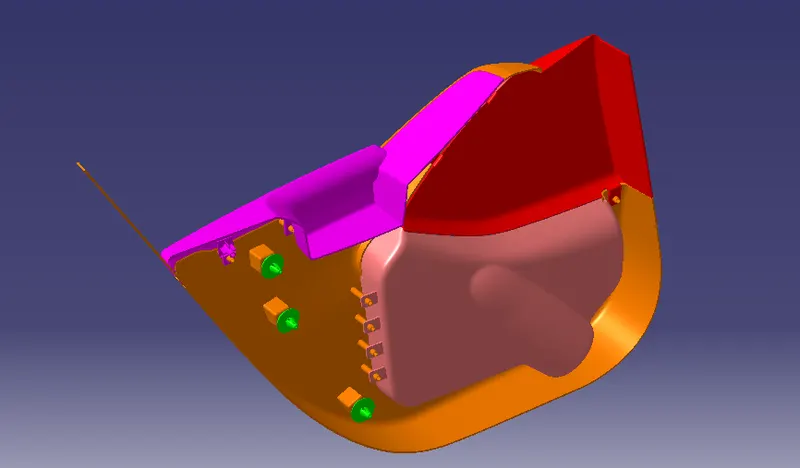
- Assemble the push pin
Components involved in the Door panel are-
- Lower Substrate
- Door Arm Rest
- Lower Map pocket
- Map Pocket
Automotive Door Panel
The door panel is the interface between the interior of the car and the inner working to the door, and between vehicle occupation and the door. they are expected to meet a variety of Specifications regarding safety, aesthetics, and functionality. generally door panel is divided into the parts like door armrest , a lower substrate , map pocket, lower map pocket, for easy design. The door currently has an inner full-width panel consist ting of electronic windows central locking system and speakers. these panels typically consist of a foamed core covered with either textiles or plastics.
An additional Consideration is their ability to protect occupation from injury during a side collision where most injuries are inflicted on the chest and pelvis as a result of crushing force of the door
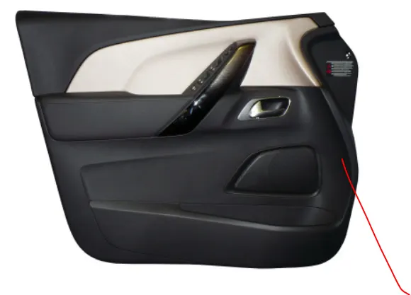
Door Panel Materials
Door panels were formerly made of cardboard with an upholstered interior finish of vinyl, leather, cloth, carpet, or other materials for the decorative trim. modern cars typically have door cards made of plastic, most often using injection molding as well as incorporating other decorative materials.
components of Door Panels
Class A surface
Class A surface for the Automotive door panel is received from the stylish team, In the automotive Industry for Class A surface Separate team is allowed to design Class-A surface this is the first input for design for plastic parts.
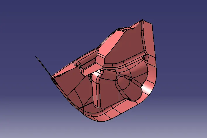
before proceeding to further design first check the class A surface if there is any gap then modify the class A surface
Tooling Axis
Creating a tooling axis
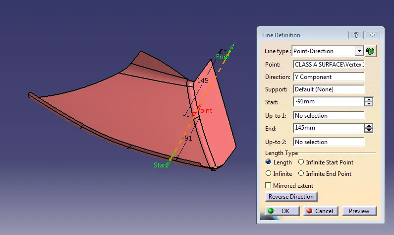
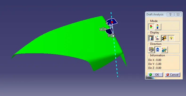
The tooling direction is used to find the direction in which the parts are removed from the core and cavity by using a tooling axis draft analysis is formed for each component.
MAP POCKET
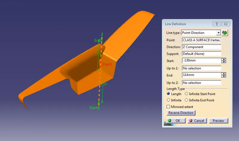
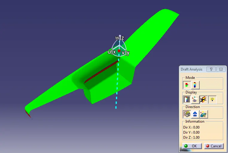
Creating a tooling direction on the map pocket, create a point on the class A surface respectively as 0 value, then create a line with respect to the Y-direction. Also, check a draft analysis for the given Class-A Surface.
OUTER MAP POCKET
Creating a tooling direction on the map pocket, Create a point on the Class A surface respectively as 0 value than, create a line with respect to the y-direction Also checking a draft analysis for the given Class-A surface.
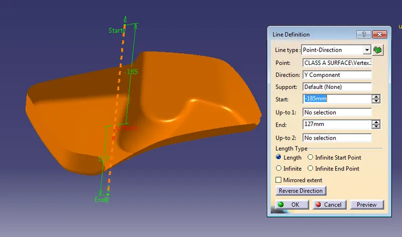
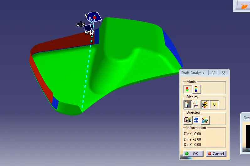
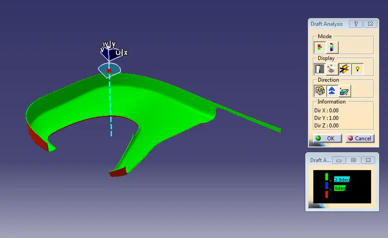
But performing a draft analysis for class A surface of lower map pocket some area shows a blue surface as 0 degrees here we don't have to right to modified class A surface so we need to inform to class A team to provide a draft angle.
LOWER SUBSTRATE
Creating a tooling direction on the Map pocket, Create a point on the Class A surface respectively as 0 value, then create a line with respect to the y-direction also checking a Draft analysis for the given Class A.
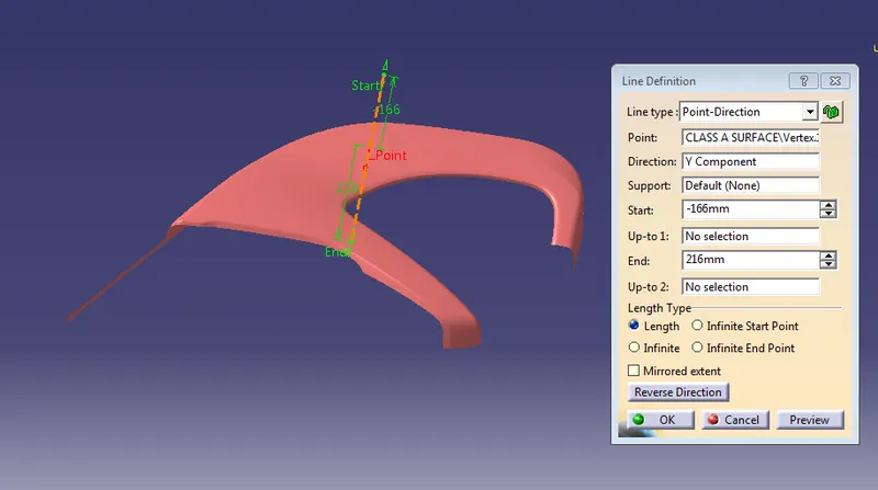
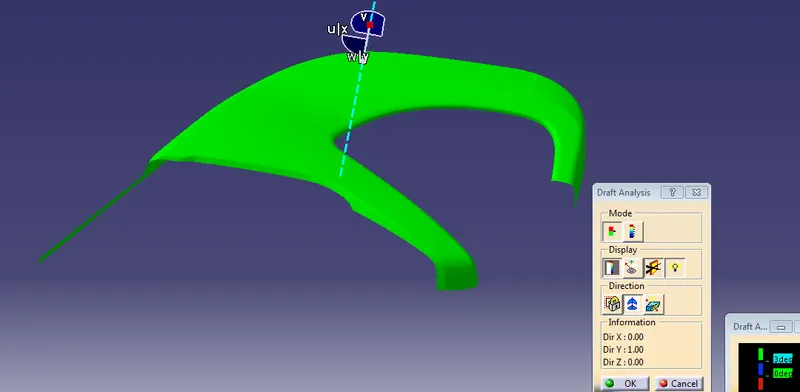
DOOR ARMREST
Creating a tooling direction on the Door Armrest, Create a point on the Class A surface respectively as 0 value, then create a line with respect to the y-direction also checking a Draft analysis for the given Class A.
CLASS B SURFACE---
OUTER MAP POCKET
MAP POCKET
LOWER SUBSTRATE
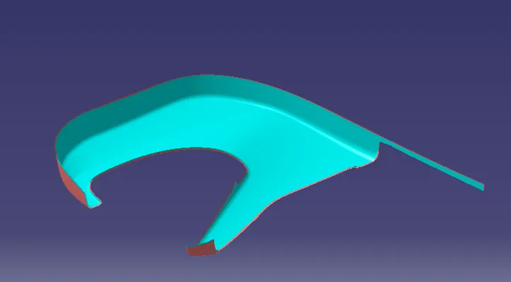
DOOR ARMREST
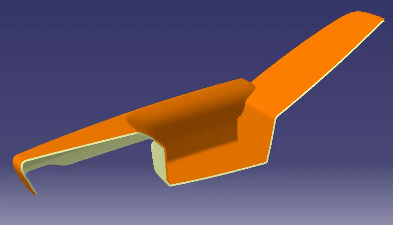
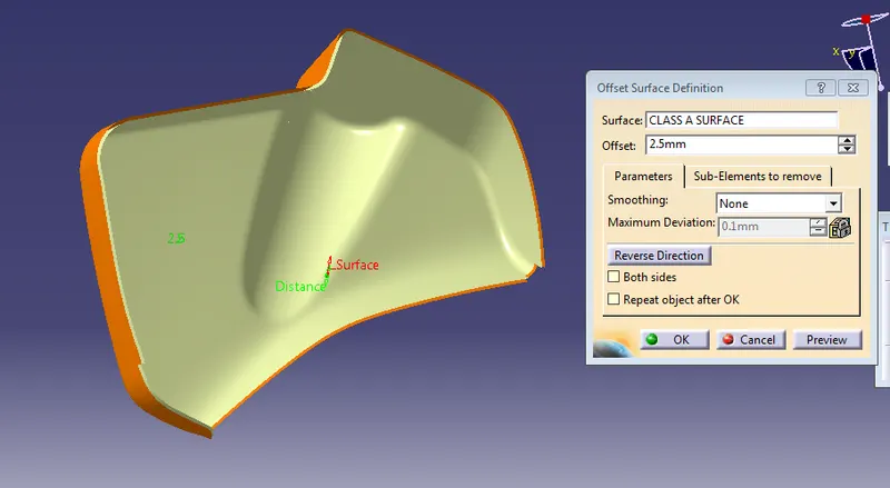
Finally by doing an offset of 2.5 mm by using master section Distance. We have got Class B surface
CLASS C-SURFACE
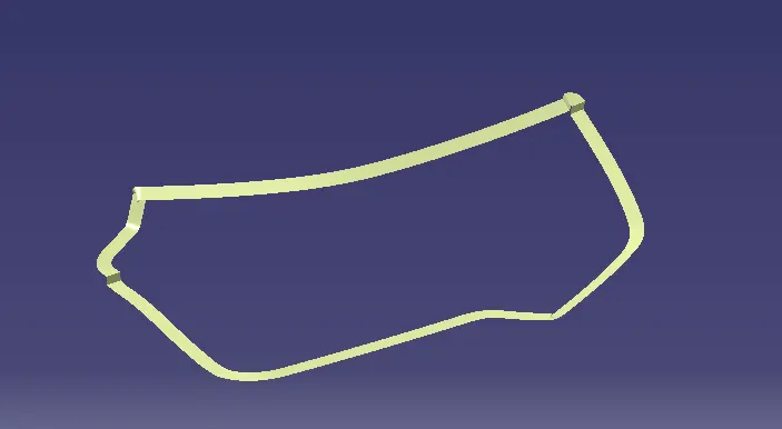
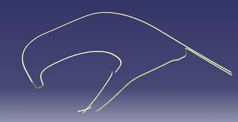
By extracting the boundary of class c surface and at the edges then make into them by using a smooth curve and sweep command to make c surface.
OUTER MAP POCKET:-
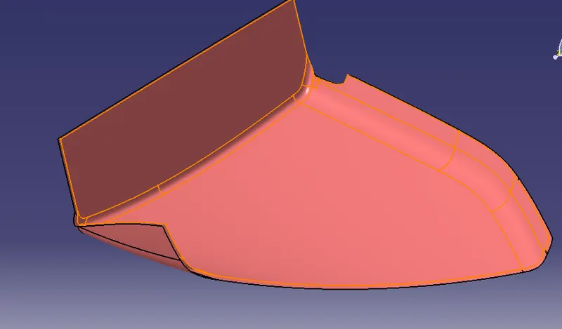
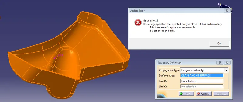
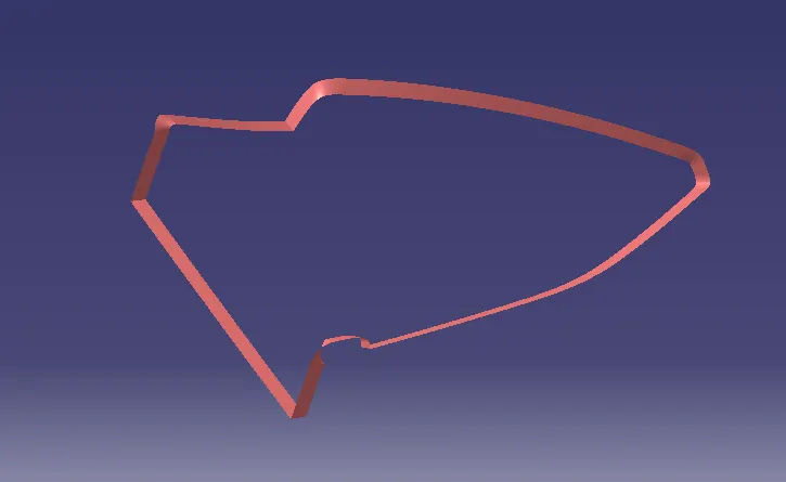
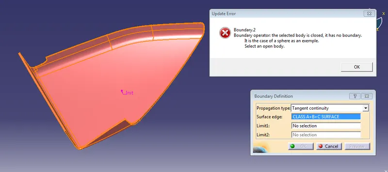
After trimming with Class C with Class B Surface and then joining with Class A surface, finally, we get the closed surface to know that use boundary option it shows as the selected body is closed.
MAP POCKET:-
LOWER SUBSTRATE:-
DOOR ARM REST:-
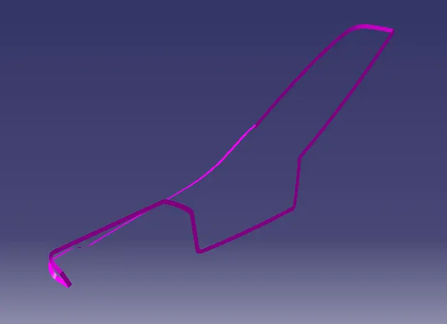
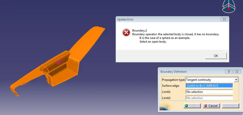
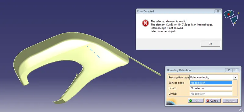
After extracting a boundary of class A surface then extrapolates a surface of class B surface up to a certain distance to trim with class A surface to C surface. Finally closed surface is formed.
DRAFT ANALYSIS FOR CLOSED SURFACE
MAP POCKET
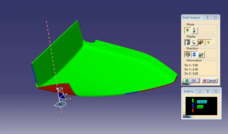
As per the color scale, the minimum draft angle for all faces should be 2.9 deg or above, inside the color scale, green shows a draft angle of 2.9 deg, blue shows between 0 to 2.9 deg red shows a negative draft angle as per the above figure, all face are green. hence this component has draft analysis successfully.
OUTER MAP POCKET
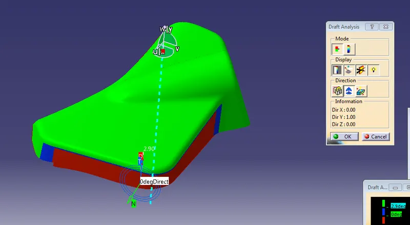
In this figure, the minimum draft angle for all faces should be 2.9 deg or above, in this color, the scale shows a draft angle of 2.9 or above. blue shows between 0 to 2.9 deg and red color show a negative draft angle, as per the above figure some faces are green, blue, and red as well hence the surface is not cleared the draft analysis at the red faces and blue faces using the main tooling axis. the minimum draft angles at the blue face are 0 deg so the class A surface needs to be given a proper draft, and required changes are forwarded to the stylish team for modification.
LOWER SUBTRACT
DOOR ARM REST
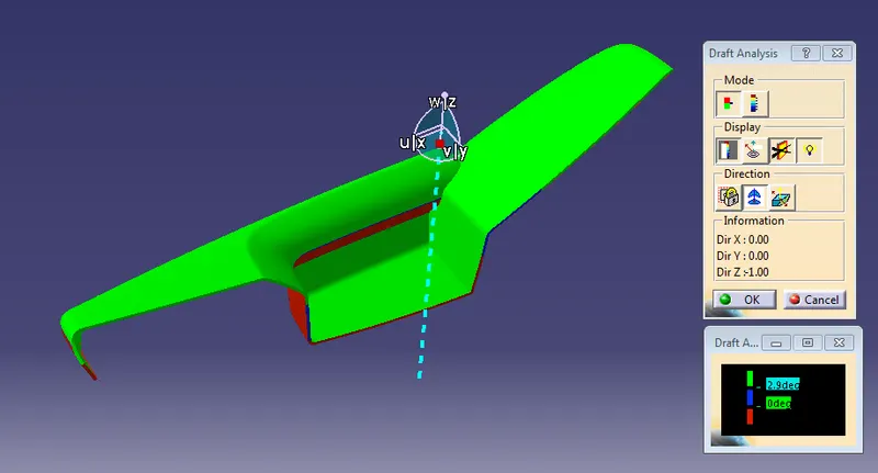
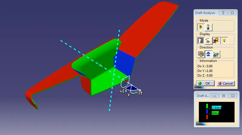
In the door, the arm rest main tooling axis clears the upper surface as shown in the figure as green color but under the cut, a tooling axis is required for the side core tooling axis is created.
ENGINEERING FEATURE / B SIDE FEATURES
In the Door panel, all the parts are attached together by using B-side features like heat stake , Screw bosses, 4-way locators, flanges, and a Dog house.
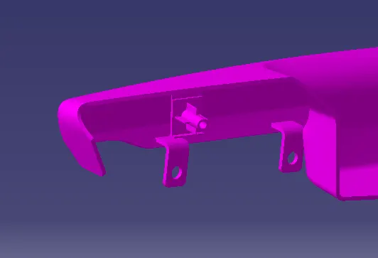
Flanges are attached to the map pocket, outer map pocket, arm rest. The remaining features are placed on the lower substrate which will act as central parts for all the components it is mainly used to joint the remaining parts.
Flanges
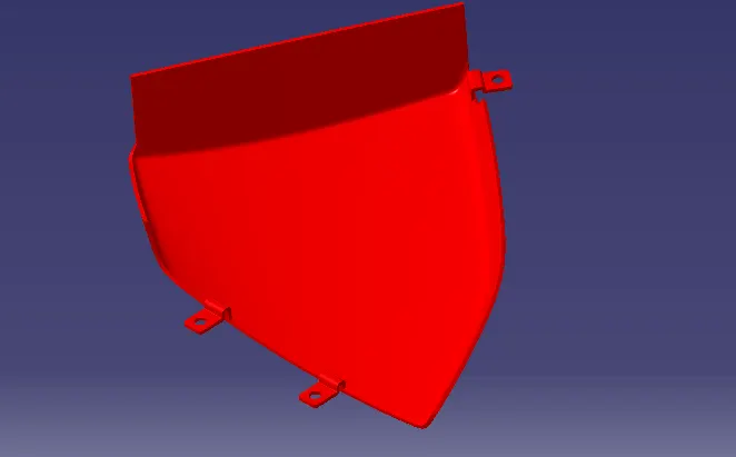
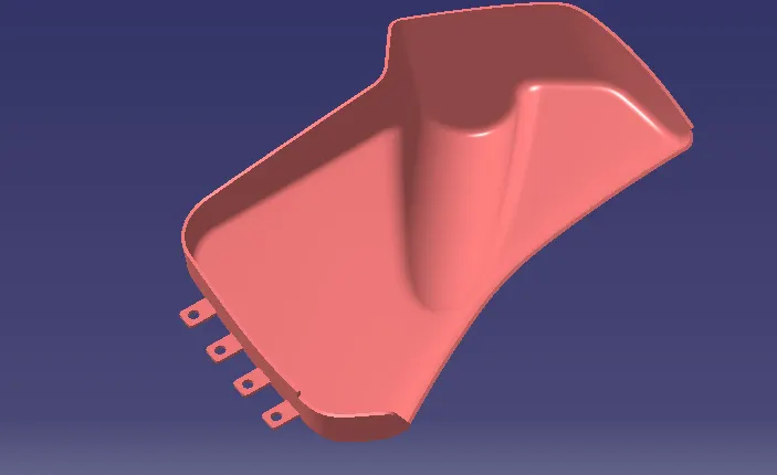
All the flanges have been created by following the given master section. the thickness of the flanges is 2.5mm, the draft angle is 0.5 deg applied to all the flanges. Edge fillet of 5mm applied to sharp corners. slots for locators and heat stakes have been created onto all the flanges.
DOOR ARM REST
MAP POCKET
OUTER MAP POCKET
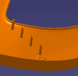
HEAT SKAKE
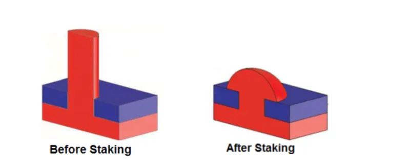
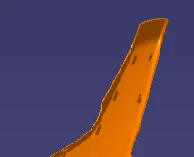
The use of heat stakes is to attach two plastic components permanently, a total of 11 heat stakes were placed at different locations on the lower substrate .one heat has been created into armrest parts which will be attached to the upper substrate. Following the master section, the outer diameter of the heat stake is 7mm and the inner dia is 5mm, necessary slots are made onto other parts where the heat skate will attach together, and a draft of 0.5deg has been given to all the heat stake.
SCREW BOSSES
The boss is one of the basic design elements of plastic molding, bosses are usually cylindrical because that is the easiest form for the machine in the mold and it is also the strongest shape to have in the molded part. the boss is used whenever we used a mounting point, a location point, or a reinforcement around holes. the boss may receive an insert, a screw, or a plain either as a slider or a press fit.
In other words, the boss is not as simple as it looks depending on its use, it may have to stand up to a whole combination of force- tension. compression, torsion, flexing, shear and bursting so it must be designed accordingly.
We can start with a general design rule, using the principle we have already developed for ribs and walls the boss can be thought of as a special case of the ribs. one that is wrapped around in the form of a tube. an ideal boss, designed according to the rib rules, would not produce a sink mark or stick mark in the mold but unfortunately, the tubular form of the boss would not be strong enough in most cases, in a compromise between sink mark and functionality. rigidity is the simplest aspect of boss design. this can be achieved by supporting the boss's design this can be achieved by supporting the boss with a buttress rib, and often by linking the boss to a side wall. the support ribs can be designed to normal rib rules so that sink marks and stress points are avoided.

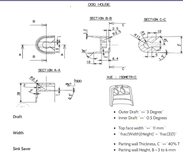
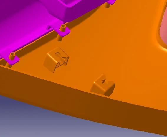
DOG HOUSE
The dog house is an engineering feature used in plastic design. Dog houses are used as supporting features sometime other engineering features like snaps, locators, etc are mounted on them to increase their strength. Dog houses are subjected to draft analysis to prevent breakage of the components during ejection from the mold cavity. dog house and other engineering components are built on the B surface.
ASSEMBLY PART
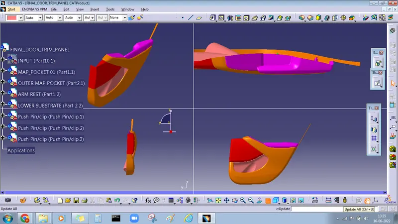
The component is created in separate part files and then inserted into assembly files they are assembled at their working position by applying constraints to them. to create an assembly using this approach, it is recommended to insert the first components and fix their position after properly orienting them in the 3D space the components can be inserted and positioned with reference to the first components.
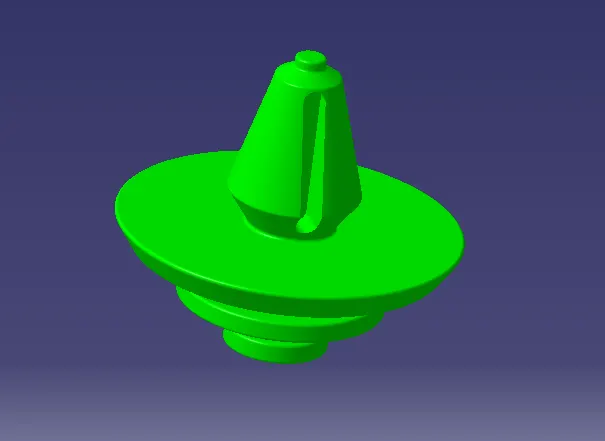
PUSH PINS
The use of a plastic push pin is to attach the plastic part to the sheet metal part.
CONCLUSION
The Door panel has been successfully designed by following OEM standards used in the automotive industry. all the attachment features are properly placed at different locations. the designed parts meets all the designed objrctives.
THANKU