Week 11 - Final project
AIM:To design and develop a CAD model (Door Trim panel) for the interior of a vehicle with a given Class A Surface and by refering to the given Master section for norminal thickness.Attachment features to be added to the CAD model following the design rules applied for the design of a Plastic component.
OBJECTIVES:Creation of CAD model considering following inputs as like in OEM and tier1 companies
a) Class A surface
b) Nominal thickness : Refer master sections
c) Attachment strategy
d)Create thickened part using master section for reference
e)Create the mounting features as per design guidelines in the industry and with master sections
f)Apply material details :
- Draft analysis & Tooling analysis.
- Creation of parting lines and check tooling feasibility.
SOFTWARE:CATIA V5
INTRODUCTION: Door trim panel is an essential part having various engineering features mounted onto it and safety features attached but also maintaining maximum thickness from 2mm to 2.5mm.Door panels serve as an interface between the interior of the car and the inner workings of the door,vehicle occupants and the door. They are expected to meet a variety of design specifications regarding safety, aesthetics, and functionality.It continues the material theme of the dashboard and pillars while concealing intricate electrical and mechanical components for operating locks, windows, and other features. It has been divided into 4 sub parts which make the door trim panel during assemble.The individual parts of door trim panel are
- Lower substrate
- Upper map pocket
- Loweer map pocket
- Door arm rest
PRODUCT DEVELOPMENT STAGES
Product life cycle along with explaination are listed below:
- Concept sketching: This stage helps a designer to explain his/her ideas or a concept model to others in a graphical manner,drawings 2D and 3D,visualizing it for better understanding and explaining.
- Styling Class A: The concept sketch will be analysed and virtually recreated using the software "Alias" for further developments and testing.
- Feasibility check: This is done on a product in order to reduce time and cost of manufacturing thereby using existing components/parts that meet the requirement also termed as "Carryover" process.
- Concept of validation: The concept is validated based on design rules,visibilty checks,safety checks and master sections development.
- New product design: After validating,the new virtual product will be ready to be sent into manufacturing.
- Development: This process involves both manufacturing and design teams to develop the physical product.
- Protobuild: This stage gives a first hand experience of the product and checked for further improvements and analysis.
- Design validation: This stage provides information that the protype model meets the end goal of its purpose.
- Pilot build: Minor changes are done by rectifying defects,if any during manufacturing process but does not allow major changes in the design of the product.
- Mass production: This stages allows to mass produce the product according to its market demand and usage.
NOTE: As a plastic product designer,we will be working on Feasibilty check, Concept of validation, New product design from the above 10 product life cycle stages.
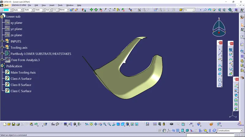
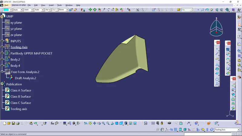
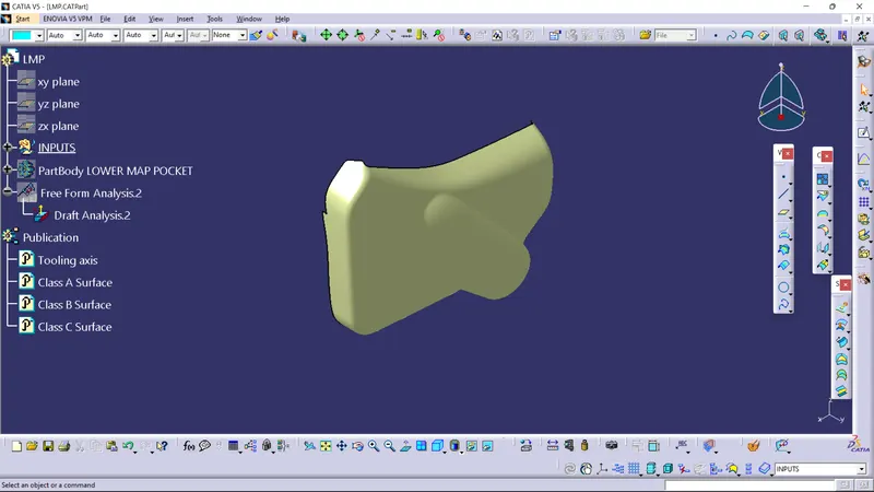
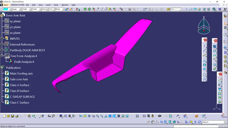
GIVEN Class A Surface of the Door Trim Panel components
Note: We have to check the boundary of Class A surface,if no open boundaries found we can perform Draft analysis.Any open boundaries found,we must report it to the Class A Surface engineer to rectify it or get permission to work on Class A Surface as per industry rules.
- Lower substrate
- Upper map pocket
- Lower map pocket
- Door arm rest
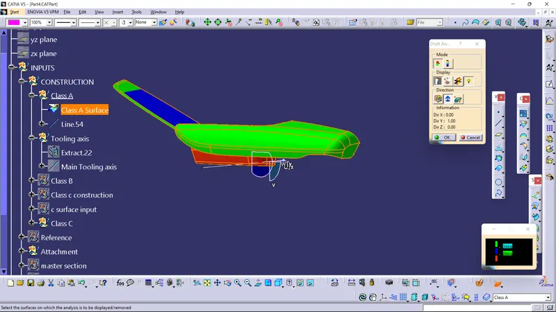
Draft analysis for the given Class A Surface
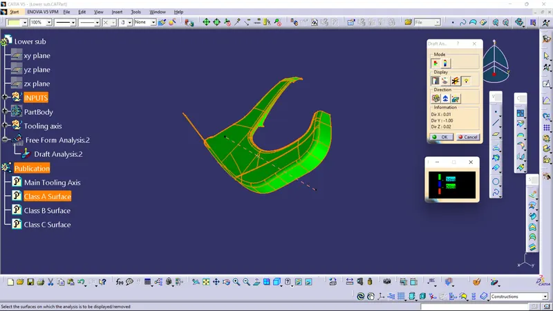
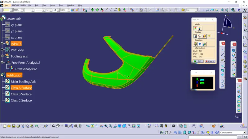
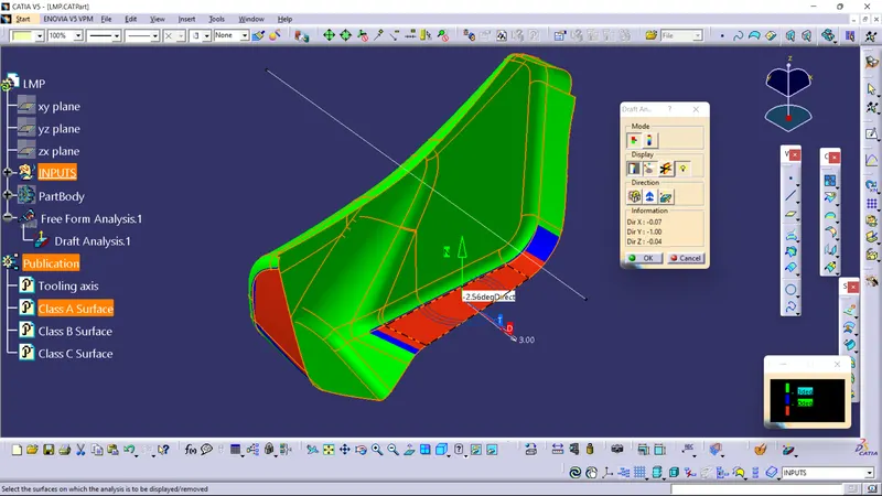
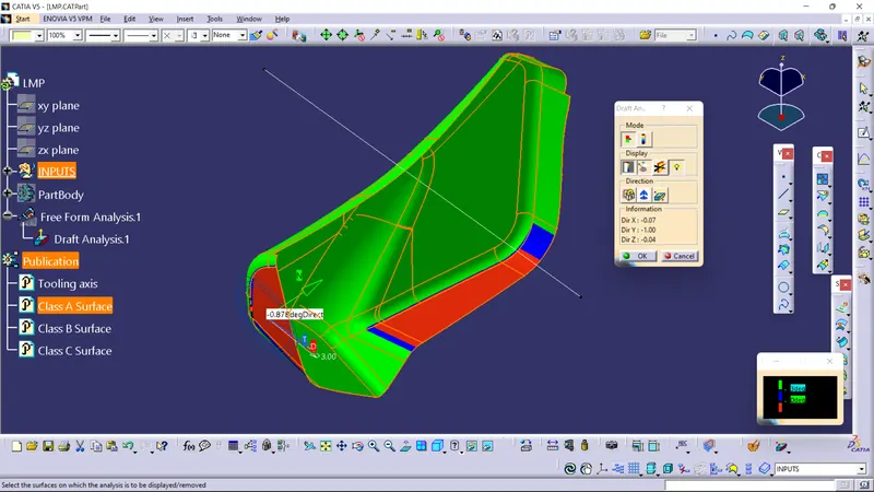
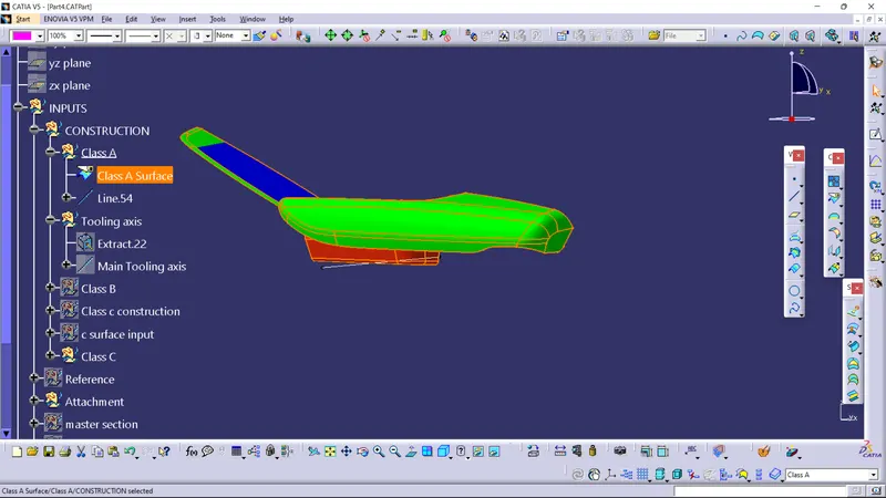
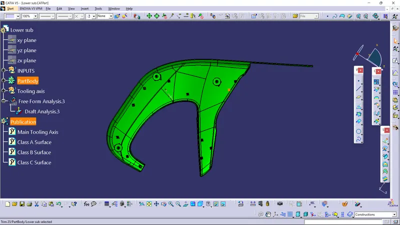
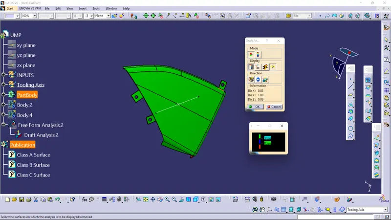
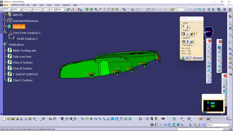
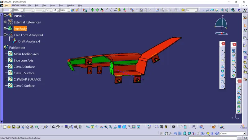
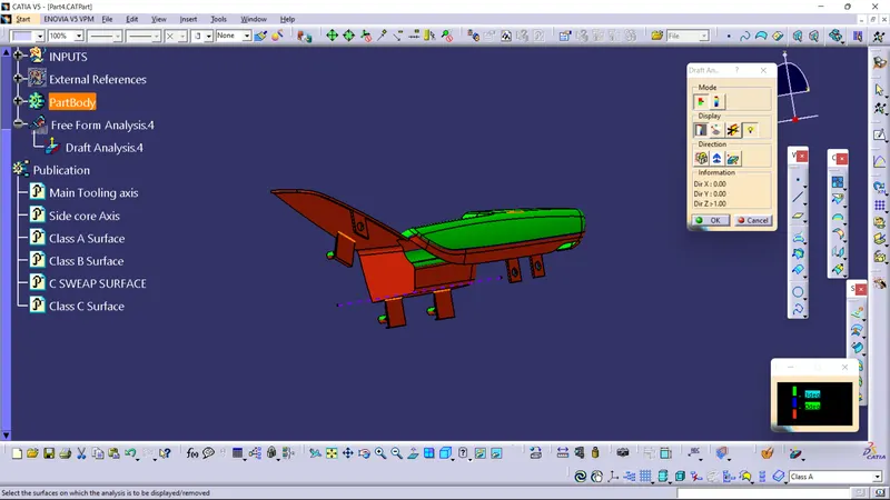
DRAFT ANALYSIS: Draft is given to a product so it gets cleared easily with the tooling axis. Draft of 3 deg is given throughout and some attachment features can be given 0.5 deg to 3 deg.The component will turn GREEN if it gets cleared. BLUE indicates that its on the inverse direction to the given compass,both are acceptable,if RED shown then the product is not cleared.
PROCEDURE TO PERFORM DRAFT ANALYSIS:
In surface workbench we can select from above toolbar Insert -> Analysis -> Feature Draft analysis.
In Part workbench we can select Analysis from the Analysis dialog box
- Lower Substract. Tooling axis along Normal to surface.
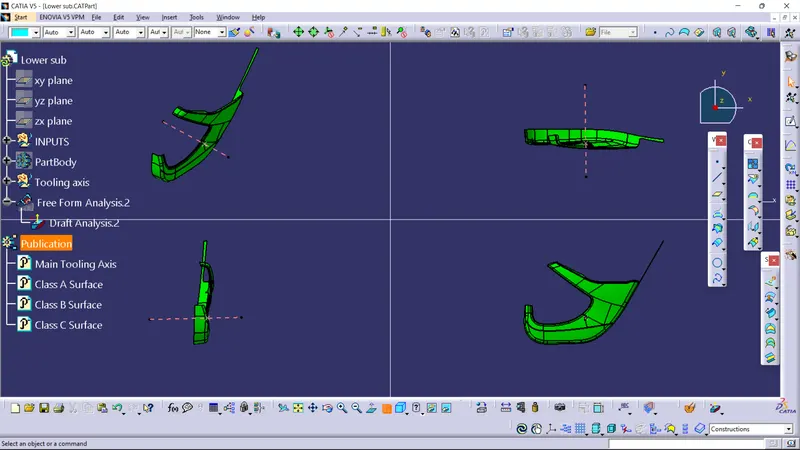
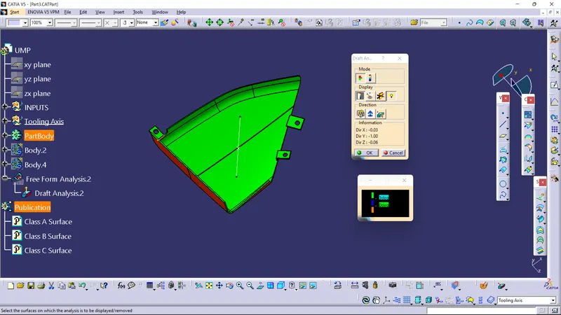
- Upper map pocket.Tooling axis along Normal to surface.
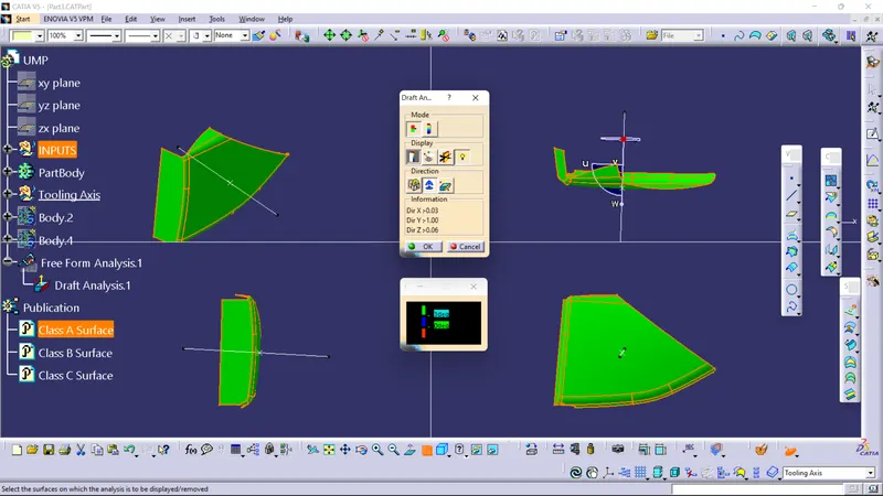
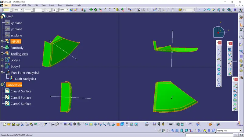
- Lower map pocket.Tooling axis along Normal to surface.
The RED portion indicates during draft analysis shown that the Class A surface has issues,so we have to inform the same to Class A Surface engineer.For this project we can start with product but have to note that the final product will also shown RED in these areas.
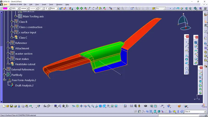
- Door arm rest faces getting cleared with Main Tooling Axis
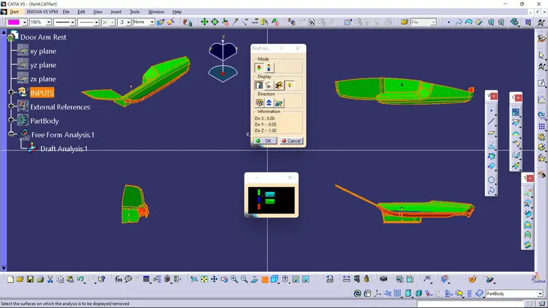
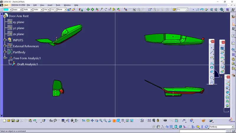
- Door arm rest faces not getting cleared with Main tooling Axis (Z axis)
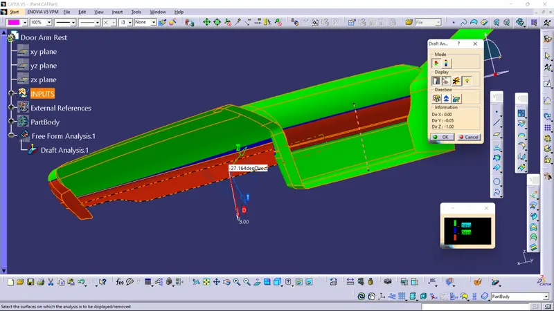
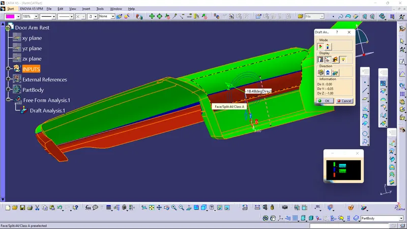
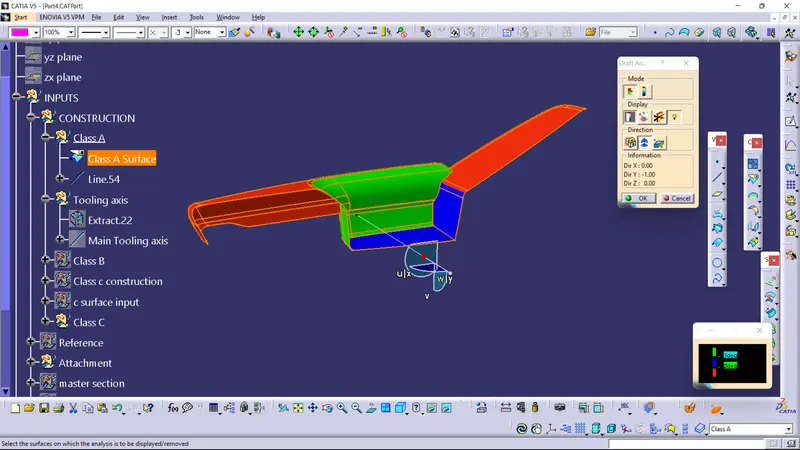
- Door arm rest faces not getting cleared with Main tooling Axis(along Z axis), So using Side Core Axis (along Y axis) to clear only the above faces.
GIVEN Master section for the Door Trim Panel
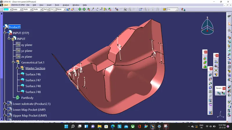
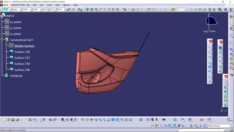
MASTER SECTION : It is provided to indicate the thickness of the part component and points where the attachment features that are to be installed.A third line near the thickness will indicate that the extra soft layer(leather or any premimum material) will be installed to give preminum finish and extra softness while the customer rests arms onto it within the interior cabin of the vehicle.
List of Attachment features to be installed
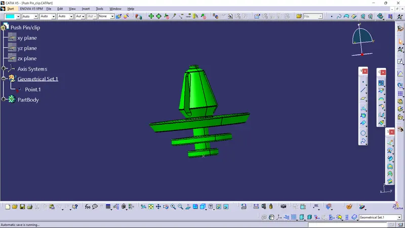
- Push pin with Dog house for Lower substrate – Door panel attachment: It is used to hold the components and fix them together without having to weld or manufacture them accordingly.This reduces the cost of manufacturing,time to manufacture and eliminating the manufacuring defeats.
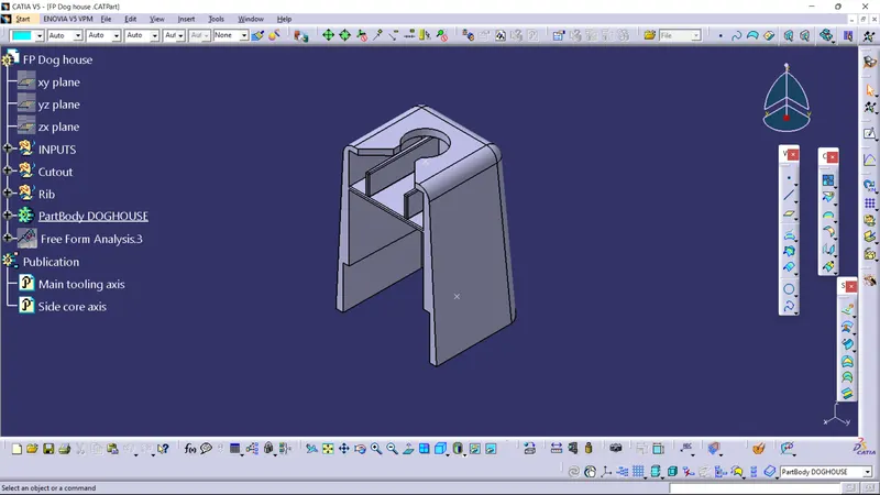
- Dog house is used to position the clips/pins at a certain height needed to fix the components,this feature helps to reduce material of the attachment and reduces possible risk of fracture or deformation if it has more height to reach the component.
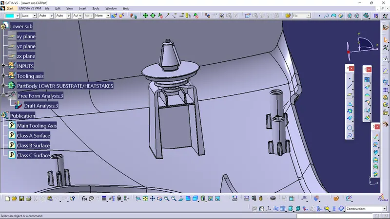
- Heat stakes for part to part attachment,This feature makes the assembly process easy and fix the components without supervision and by reducing the overall cost.
Given Class A Surface of Door Trim Panel
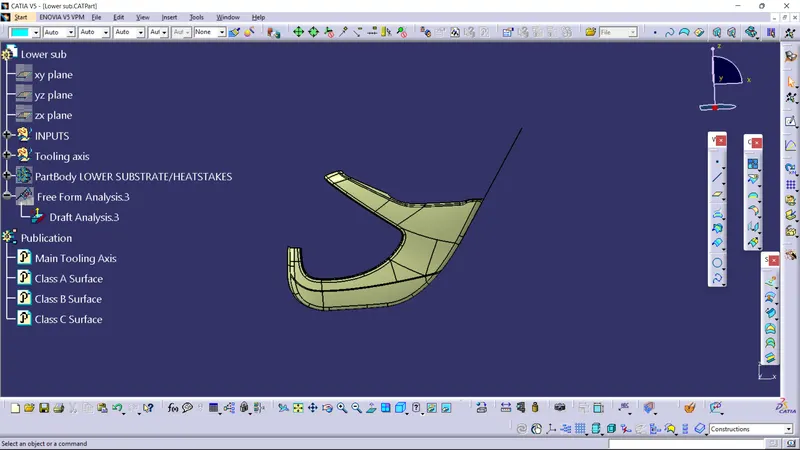
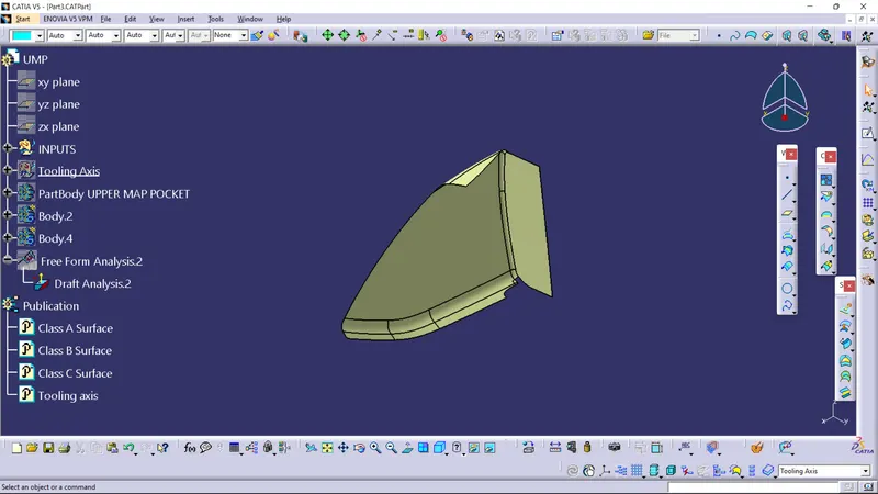
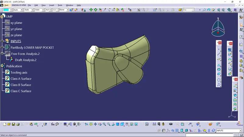
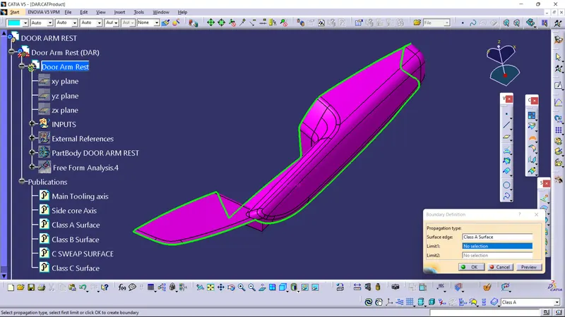
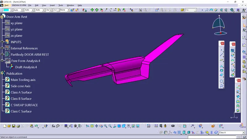
NOTE: The below Class A Surface of the Door arm rest below has boundary issue.So we have to improve it to work on it further.
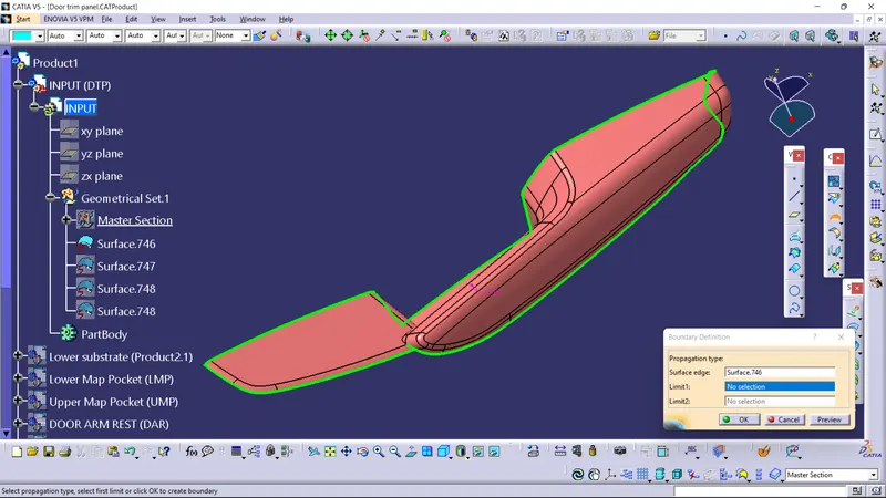
The improved Class A Surface:
Creation of Class B Surface
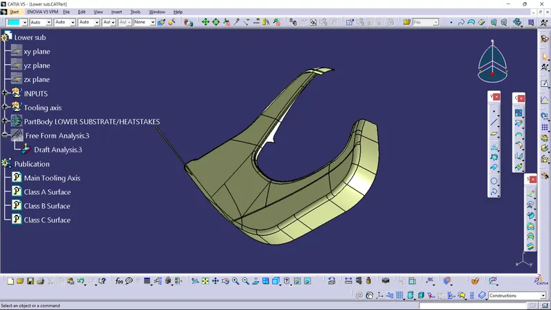
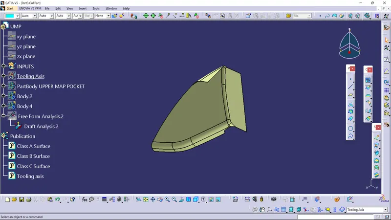
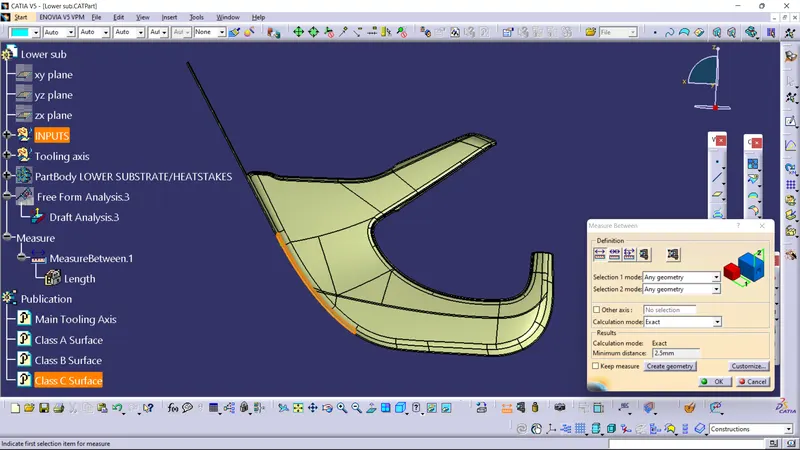
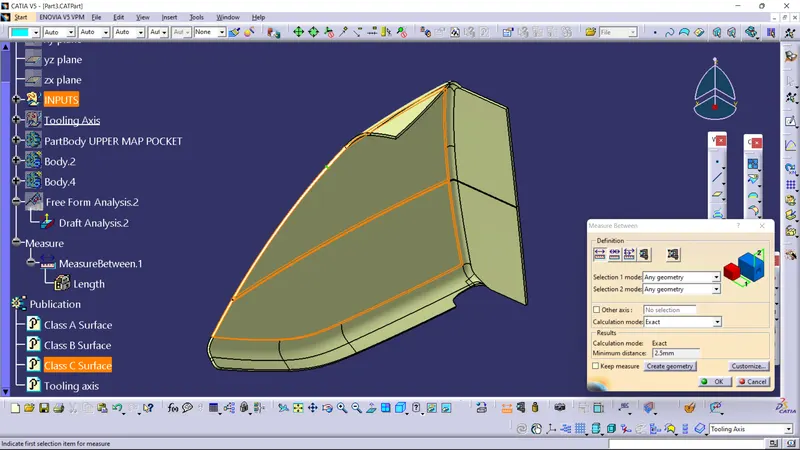
The parts below has a surface with no irregularities so we have to OFFSET it to the thickness given in master section which is 2.5mm to create the Class B surface.
The Door arm rest below has been reconstructed in few areas from Class A Surface at an OFFSET distance because of its varing surfaces.
Creation of Class C Surface, Closedbody Solid part having Thickness of 2.5mm
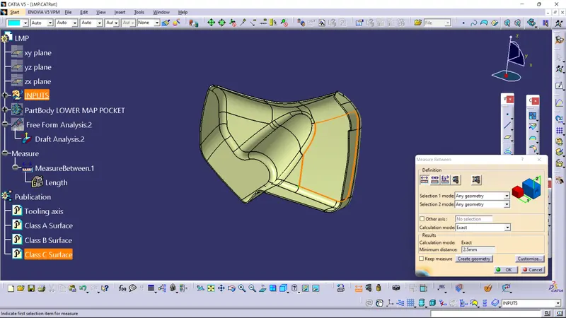
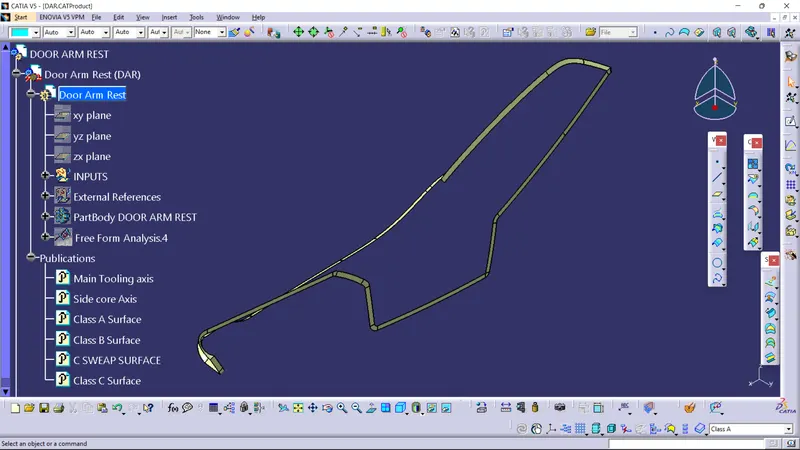
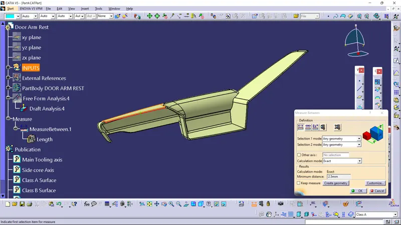
Creation of Closed body
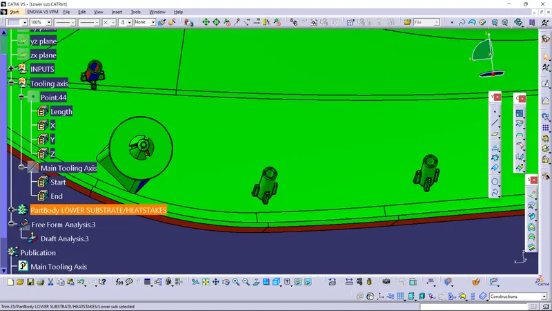
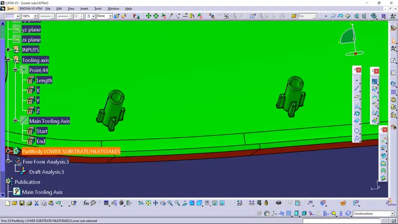
- Lower Substrate with attachment features (Dog house with push pin/clips and heat stakes) added component
To add the attachment features to the Assemble workbench,we can create the Part file and Copy/Paste it to the tree or Select New part option and browse the Part file.Once we have it in the Assembly workbench,go to Part workbench, we can use TRANSLATE option to position it at the desired location,if the plane is not similar to the lower surface we can use ROTATE option along the needed Axis created.
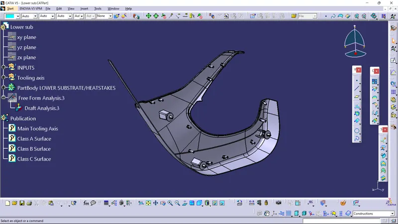
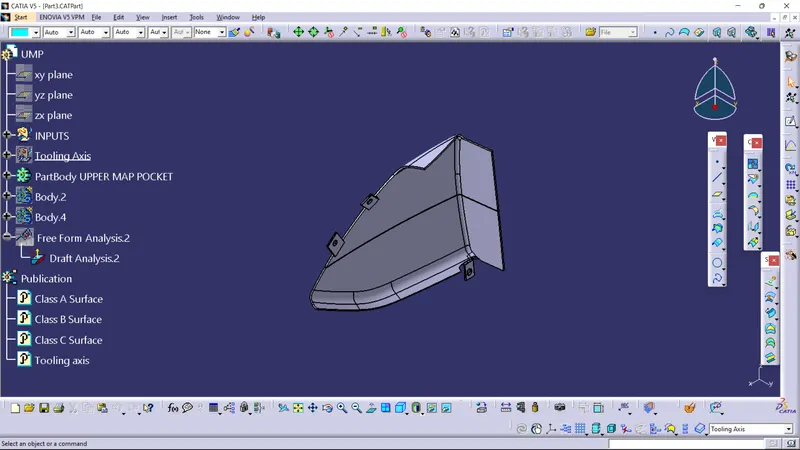
- Upper map pocket and Flanges are created to house the heat stakes for fixing the component.Flanges can vary in numbers depending upon the component
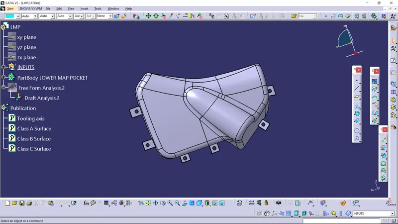
- Lower map pocket with Flanges are created to house the heat stakes for fixing the component.Analysis the fixtures we can provide the flanges
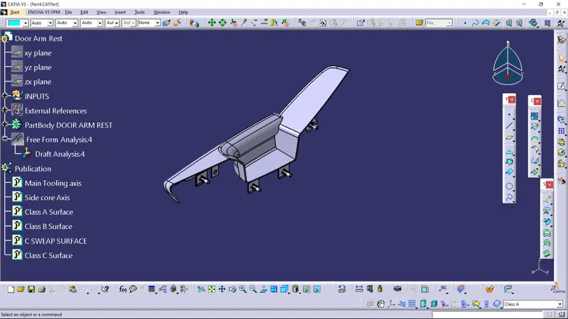
- Door arm rest with Flanges and heat stakes. More attachments are provided so that we can assemble them to other counterparts of the vehicle door that is parts between the door arm rest and metal part,like the window glass housing,power windows,Locking system or Audio system.
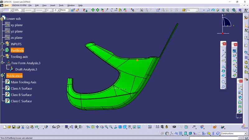
Draft analysis on Closed body individual components
NOTE: 3 deg draft angle given .Tooling axis along Normal to surface.
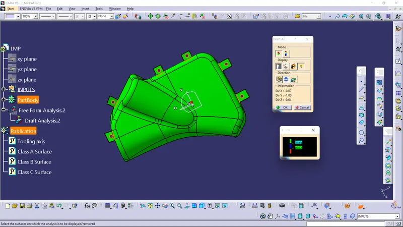
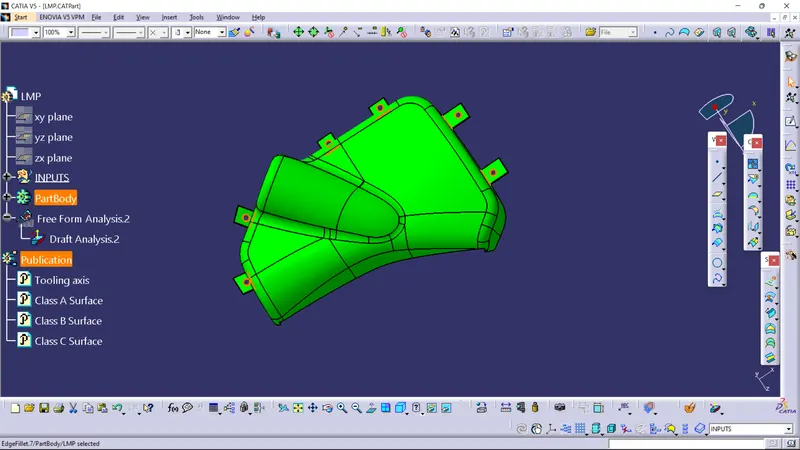
Due to Class A surface issues some portion of the below Lower map pocket closed part are not getting cleared as in Class A Surface.
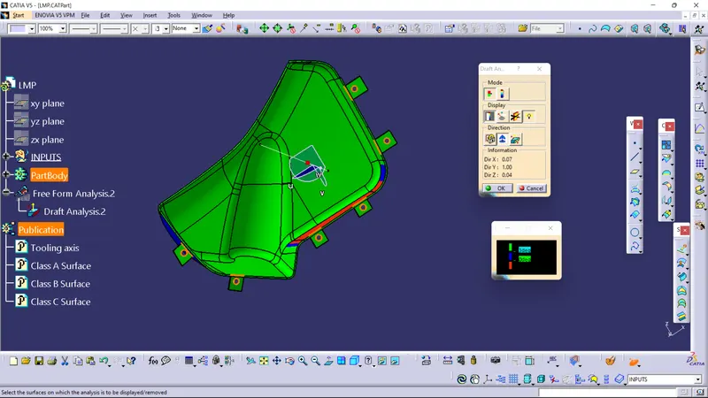
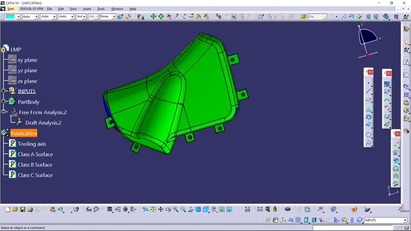
Draft analysis performed using Main tooling Axis (Z Axis)
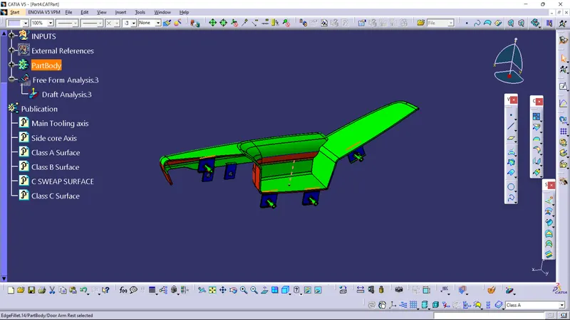
Draft analysis performed using Side Core Axis (Y axis)
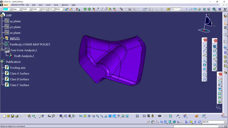
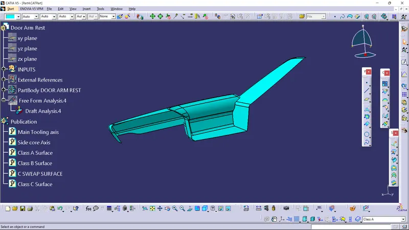
Publications: Tooling axis,Class A,Class B and Class C Surfaces are published within its CADPart file.
Creation of Attachment features
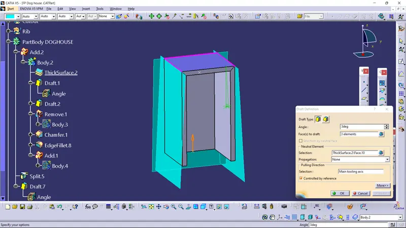
Draft angle given for the outer faces 3 deg
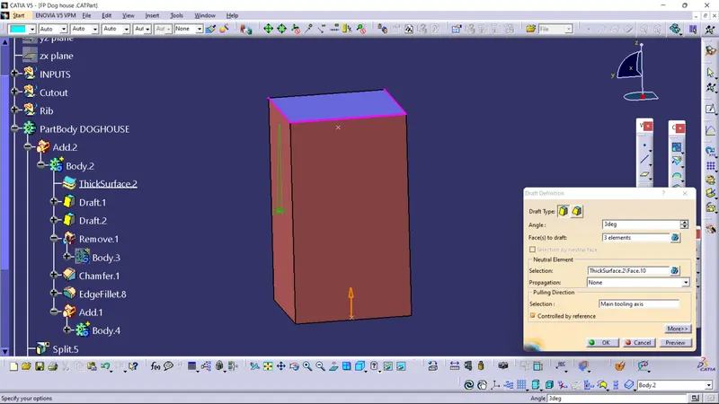
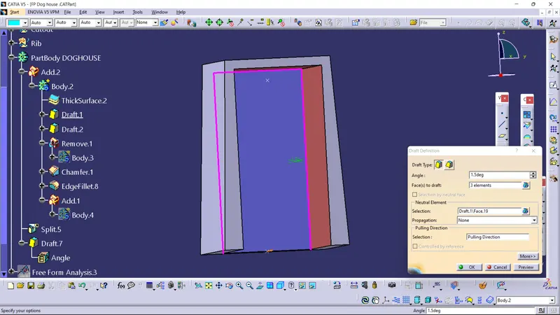
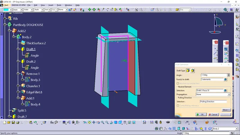
Draft angle given for the inner faces 1.5 deg
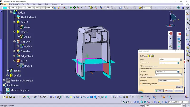
To avoid sink marks we have to maintain Thickness(C=2mm) of Doghouse and the lower portion as 40% of the "C". The split command is given for Doghouse equal to 0.8mm.Draft angle given is 0.5 deg for the split face.
Draft analysis of Attachment features
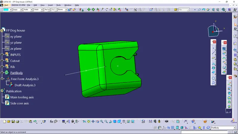
Draft angle given for the inner faces 1.5 deg.Tooling axis along Y axis
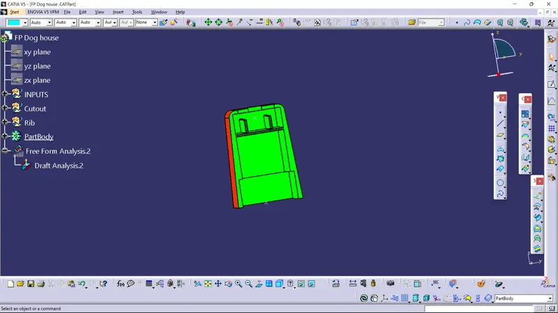
Draft angle given for the outer faces 3 deg.Tooling axis along Z axis
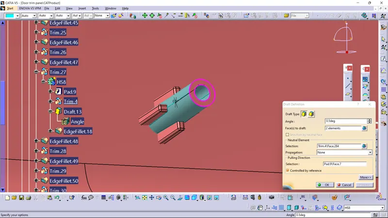
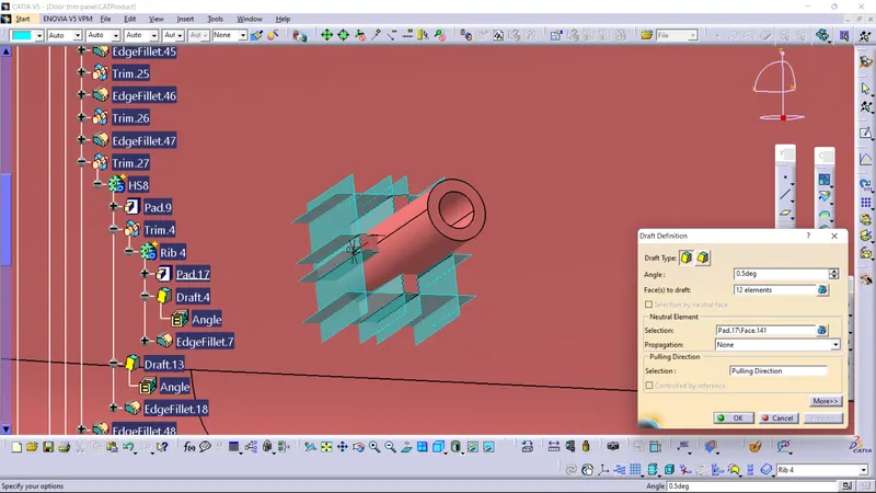
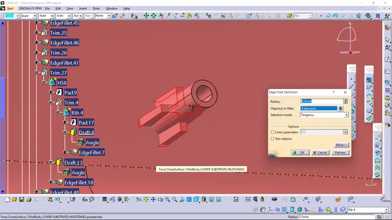
Heatstakes and Ribs draft angle given as 0.5 deg, it is cleared along the Main tooling axis (Z axis) of the Lower substrate.
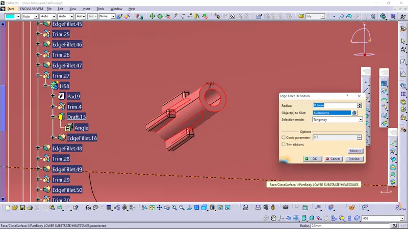
- Reference from given master section, the diameter(D) of each heatstake are D=7.5 (outer diameter) and D=4.5 (inner diameter).
- Edge fillet given as 0.5 deg
FINAL PRODUCT OF DOOR TRIM PANEL
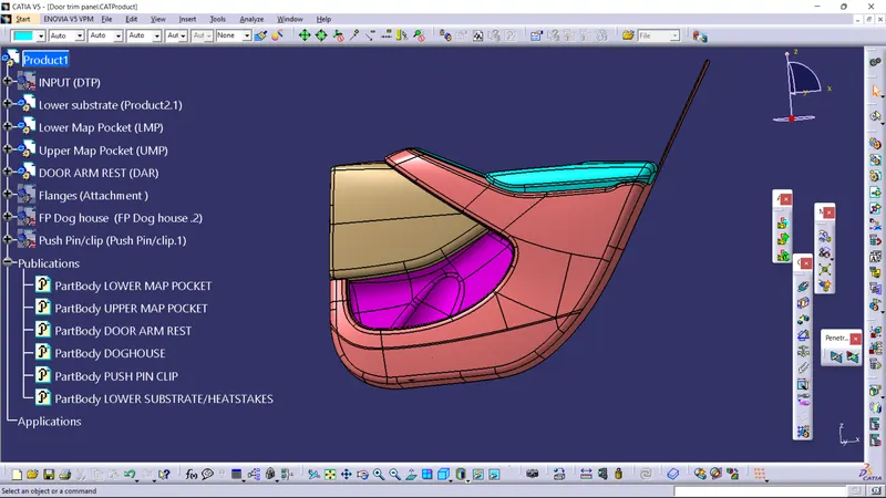
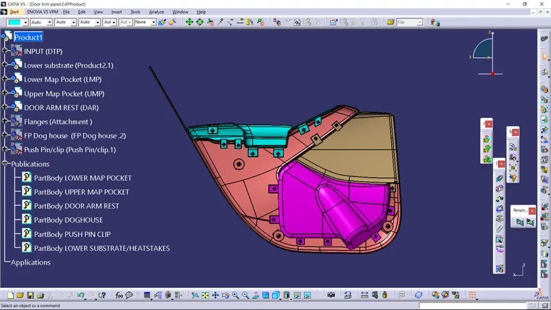
Publications:In the CADProduct file (Assembly) Partbody of the individual parts of the door trim panel are published.
NOTE: The individual CATPart files and CATProduct files are attached below.
THANKYOU.