Week 8 - Challenge 2 - Base Bracket Design
The Base Bracket Plastic component through the given Class-A surface
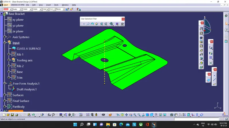
- Tree Structure showing Geometrical set as "Input"
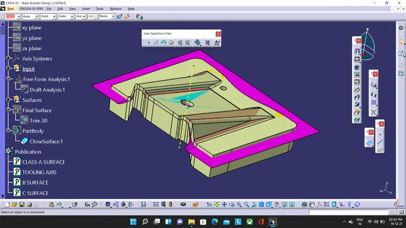
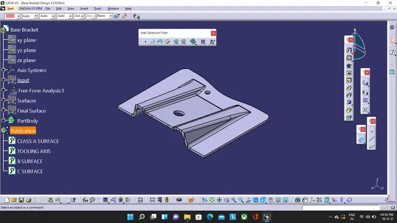
Tree structure having "Close surface" in part body and Publication having Tooling axis and Class A,B,C Surfaces.
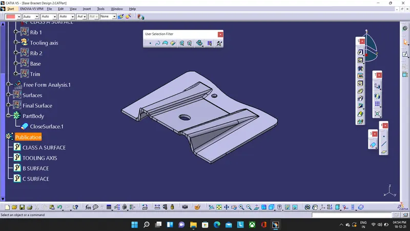
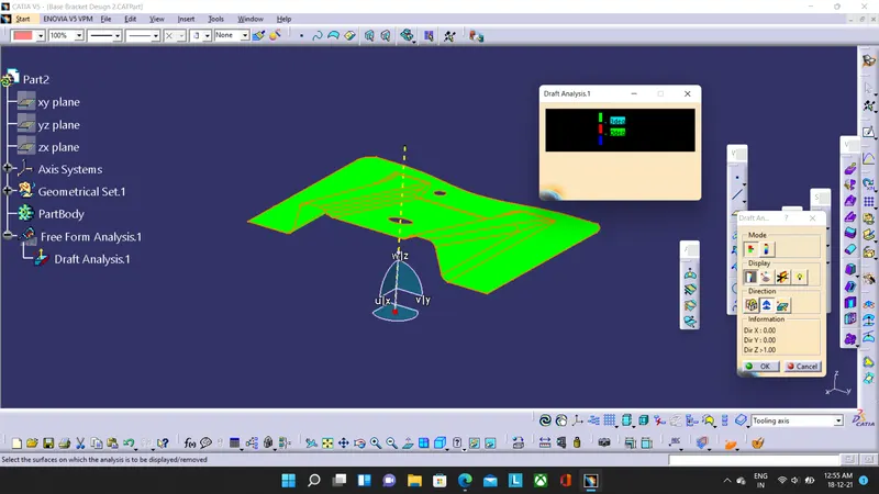
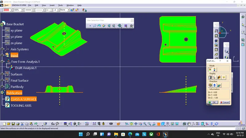
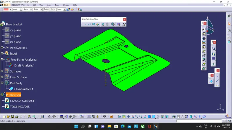
- Screenshots of the Draft analysis report for both the given Class-A surface and the final plastic component
- Screenshots of the solid model with the proper color code of the draft angle in various orientations (Isometric, Front, Side, and Top View)
The final output with Class A,B,C Surfaces of the base bracket design.
REPORT:
- A detailed report on explaining the draft analysis and the tooling axis creation.
AIM: To create a Base Bracket Plastic component through the given Class-A surface and doing draft analysis by tooling axis creation
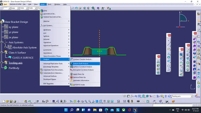
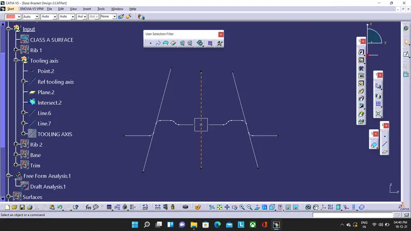
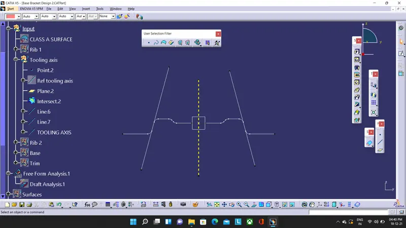
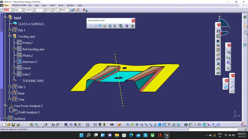
Procedure: Class A surface should be checked for boundary using "boundary" command and ensure it is a closed boundary with no open faces/edges..This design contains holes therefore tooling cannot be created along either X direction or Y direction,so Z axis is choosen for tooling axis direction and "Ref tooling axis " is created for refference.Use intersection command to intersect the class A surface on YZ plane through a support plane and point created along YZ plane.Line drawn connecting two points on both the ref tooling axis,then create line using Bisecting command as a result TOOLING AXIS is created.We use the feature draft analysis from the analysis option on the insert toolbar.Change the material mode to "Material" if error is shown.Draft analysis dialog box,select red dot on compass and the drag the compass to the "TOOLING AXIS",lock the compass and select the Class A if it changes to green then its under 3 deg with is permisable for designing the component but blue is highlighted then use the invert command beside the compass command in the dialog box.Hence Tooling axis and draft analysis will be done for the Class A surface of the base bracket design.
- An explanation should be given on the way of creating the tooling axis particularly the Bisecting method.
Tooling axis is needed to clear the component along a particular direction,for the above given base bracket design Z axis is suited as TOOLING AXIS.To create the tooling axis,bisecting method is used during line creation.A reference line is created along Z axis.Using intersecting command on the Class A surface along the YZ plane, we get the points of the faces then choose the points and create line on both sides of the ref tooling axis,hide the ref tooling axis and create a line using bisecting command by selecting both lines on either side of the ref tooling axis.Hence TOOLING AXIS along Z axis will be formed with the bisecting command.TOOLING AXIS can be changed in colour,size and spacing to identify while performing draft analysis.
NOTE:The CATPart file of the above base bracket design is submitted in ZIP file format below.
THANKYOU.